

Was it JFK who said, “The time to repair the roof is when the sun is shining?” He was likely using the roof as an analogy for the economy, but I take things literally and wanted to talk about roofs. The time to think about the design of your roof and its function in a high wind event like a hurricane or tornado is right now.

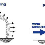
During a high wind event, a roof deck is expected to perform many functions. It should prevent water intrusion from rain, withstand impacts and protect those inside from hail. It also needs to act as a diaphragm – transferring lateral loads to shear walls and resisting the vacuum effects of wind uplift forces.So, how does a roof act as a diaphragm or resist uplift? It’s all about the fasteners. Of course, the choice of material for roof decking, along with the roof covering and how it’s attached, are important. But the attachment of the roof decking to the structure is really the key to the structural performance of the roof. How fasteners can withstand forces that cause shear, withdrawal, and pull-through will determine if your roof survives a high wind event.
1. Shear. Transferring shear is important in both seismic and high wind events. As far as the fastener is concerned, all other things being equal, the shank diameter is what’s important. The larger the diameter, the higher the shear capacity. An 8d nail will have less shear capacity than a 10d nail, same as a #8 screw will have lower capacity than a #10 screw. Proper spacing is needed to have enough shear capacity to meet demand.
2. Withdrawal. Withdrawal occurs when roof decking comes off of the roof framing and the fastener goes along for the ride. This type of failure can commonly occur with smooth shank nails or staples. Fastener choice can help alleviate the likeliness of that happening. For higher withdrawal capacity, choose a ring shank nail or screw to fasten the roof deck. For equivalent diameters, a wood screw will achieve nearly three times the withdrawal capacity of a nail. You can check this with the withdrawal equations in the National Design Specification (NDS) for Wood Construction for wood screw and smooth shank nails (Eq. 11.2-2 and 11.2-3, respectively). Or you can do a side-by-side pullout test using the claw end of a hammer, which would be more fun.
It is important to remember that fastener withdrawal resistance is given in pounds per inch of penetration into the framing. So you always need to deduct the sheathing thickness. For screws, the withdrawal capacity is based on the embedded thread length, not the total screw length.


3. Pull-through. Pull-through occurs when the roof decking comes off of the roof framing, but leaves the fasteners attached to the framing. A few different factors determine the probability of a pull-through failure. The geometry of the fastener head determines the area of decking in contact with the fastener. In addition to head size, the thickness of the roof decking material contributes to pull-through resistance – if it’s thicker material, it’ll take longer to deform around the head of the fastener.


Quantifying the pull-through capacity in wood structural panel sheathing can be challenging, as the NDS does not provide a method for calculating this. For commodity fasteners, the APA has published nailing schedules for high wind uplift in technical report T325 (free download at the APA website). When using proprietary fasteners whose values are based on testing, manufacturers will typically provide both withdrawal and pull-through capacities.

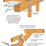
Determining the proper load demand is key to designing for shear, withdrawal and pull-through in your roof deck fastening design. It is important to remember that shear loads are based on Main Wind Force Resisting Systems (MWFRS) level loading, but uplift demand determining withdrawal and pull-through requirements is derived at component and cladding (C&C) level loading. The illustration on the right shows what a fastener spacing diagram may look like for two possible roof types in order to match the C&C uplift pressures.

Likely, we can all agree on the uses of MWFRS and C&C loading described here, but this is a hot topic in anchoring of roof trusses for uplift to the wall below. For a great article on that, see CFSEI Tech Note TN-L200-09.
How detailed do you get in your selection of roof deck fastening? Let me know in the comments.
– Paul
What are your thoughts? Visit the blog and leave a comment!


I enjoy your blog, you are doing a really nice job.
Tom
Is there a specification you can use to make sure the screws will not be brittle under cyclic loading?
There are ductility tests for ASTM C1513 tapping screws (SAE J78) and nails (ASTM F680), but there is not a specific ductility requirement in ASME B18.6.1 for wood screws. Manufacturers can (and do) set requirements for hardness and case depth, bending strength and torsional strength of the screw to achieve ductility.
Some manufacturers screws are evaluated per ICC-ES AC-120 – “Acceptance criteria for wood screws used in horizontal diaphragms, vertical shear walls and braced walls.” This criteria requires comparative testing of diaphragms using nails as the benchmark. The testing needs to show that the screws are equivalent to the code prescribed nails for strength and displacement.
Comentary from the 2003 version of the IBC – 1609.6.2.3 Load Case…
“these elements are required to be designed…. as part of the MWFRS, and separately checked for the… components and cladding. The elemnt should be designed for the more critical loading condition.
You should have mentioned nail gun nails in your blog.
A 16d nail gun nail is the length of a 16d common but it’s shank diameter is equivalent to a 10d common nail. We usually note on our drawings that if the installer uses a nail gun he must match the shank diameter of the common nail specified or add more nails.
The second thing about nail guns is they will over drive the nails if not properly calibrated. This reduces both the pull out capacity and the shear capacity of the fasteners.
thanks for the info much needed George Hewitt – Austin, TX