

If you’ve been following the Structural Engineering Blog for any length of time, you’ve probably noticed that we like to run a lot of tests around here. Building test setups and breaking them is one of the things we enjoy the most in R&D at Simpson Strong-Tie, but often load rating a product is not as simple as just running a test. At times the process requires significant time and effort, so much so that we start asking ourselves, Aren’t we done testing yet?
We’ve posted on how we test connectors, holdowns, and screws. Most products have an ASTM standard or Acceptance Criteria that sort of tells you what to test. Yet figuring out how to test a product can be a challenge – in other words, how do we make sure our test simulates installed conditions? Or maybe a product can be used in so many different ways that it is unreasonable to test every possible installation, so what to do?
We have been challenged with these situations over the years, but probably never as much as with our connectors for curtain-wall construction that we introduced about two years ago. In particular, testing our bypass framing connectors to resist in-plane loads (designated as F1 loads) presented testing challenges.
For curtain-wall designs, in-plane loads from the curtain-wall system are often transferred to the supporting structure through slide-clip and fixed-clip connectors. But the capacity of these connectors to resist in-plane loads varies widely based on the details of installation, forcing designers to make assumptions about the location of the applied load and the amount of rotational restraint at each end of the clip.

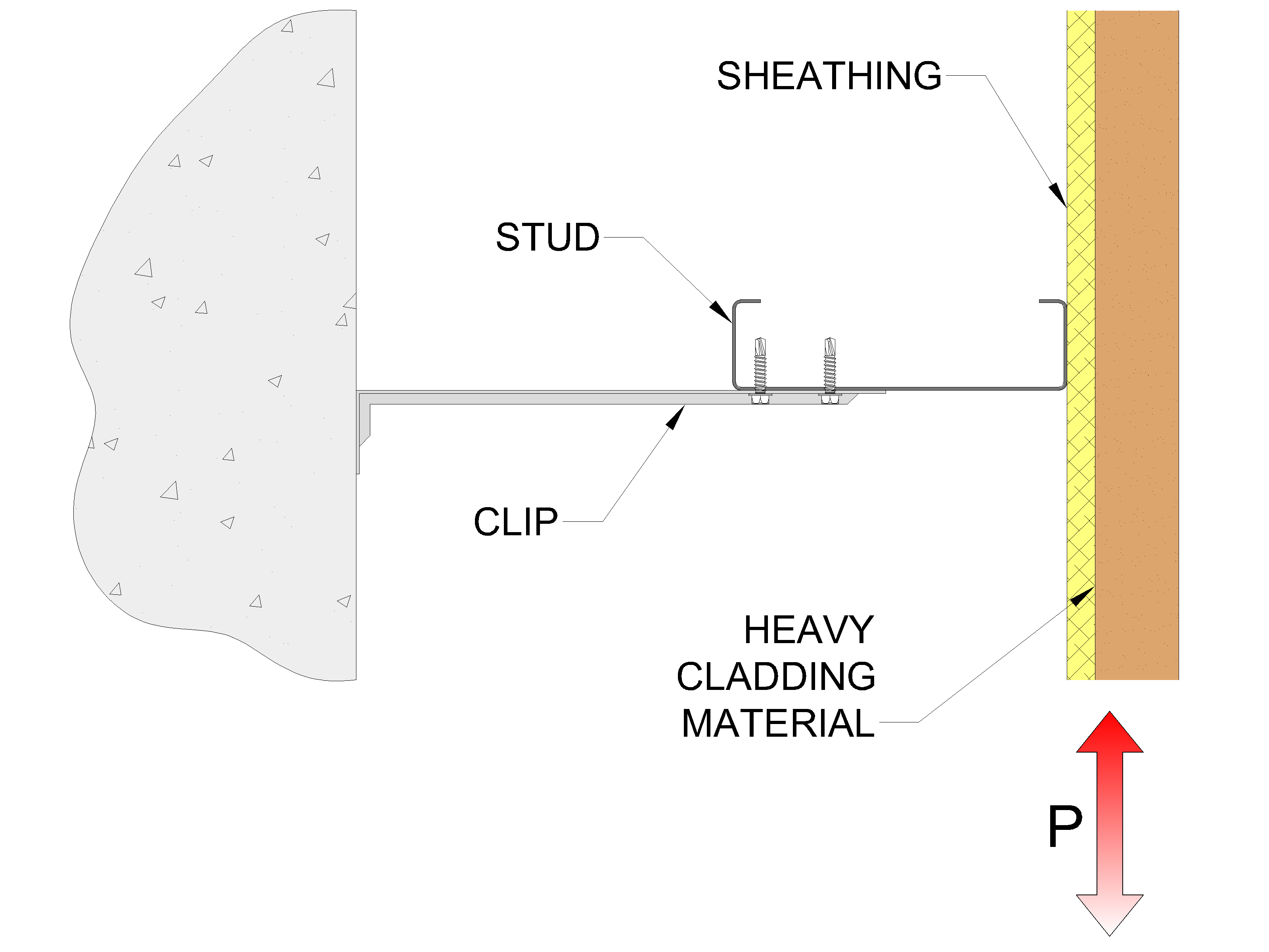
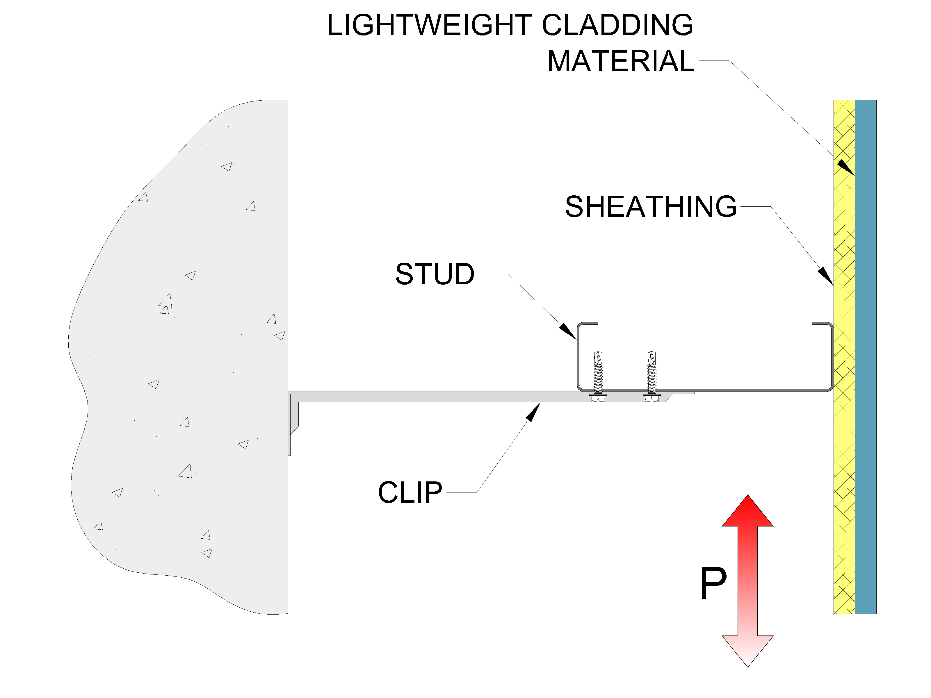
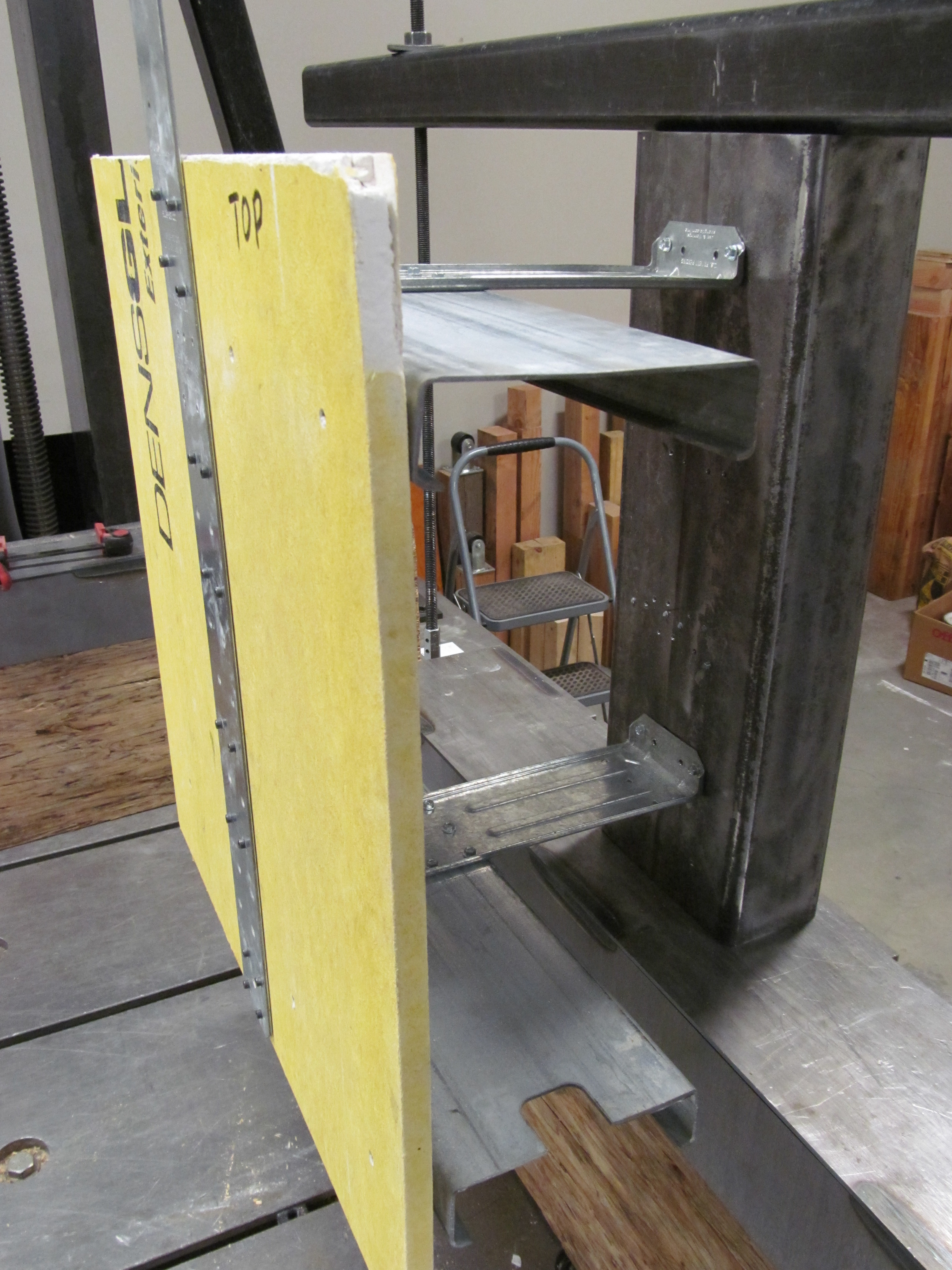
For seismic loads, the location of the center of mass of the system, and therefore the location of the applied force, will vary with different weights of cladding materials – resulting in different allowable loads for the same connector. For a heavy cladding material, the in-plane load will be located near the exterior flange of the stud, while for lightweight cladding it will be closer to the supporting structure.
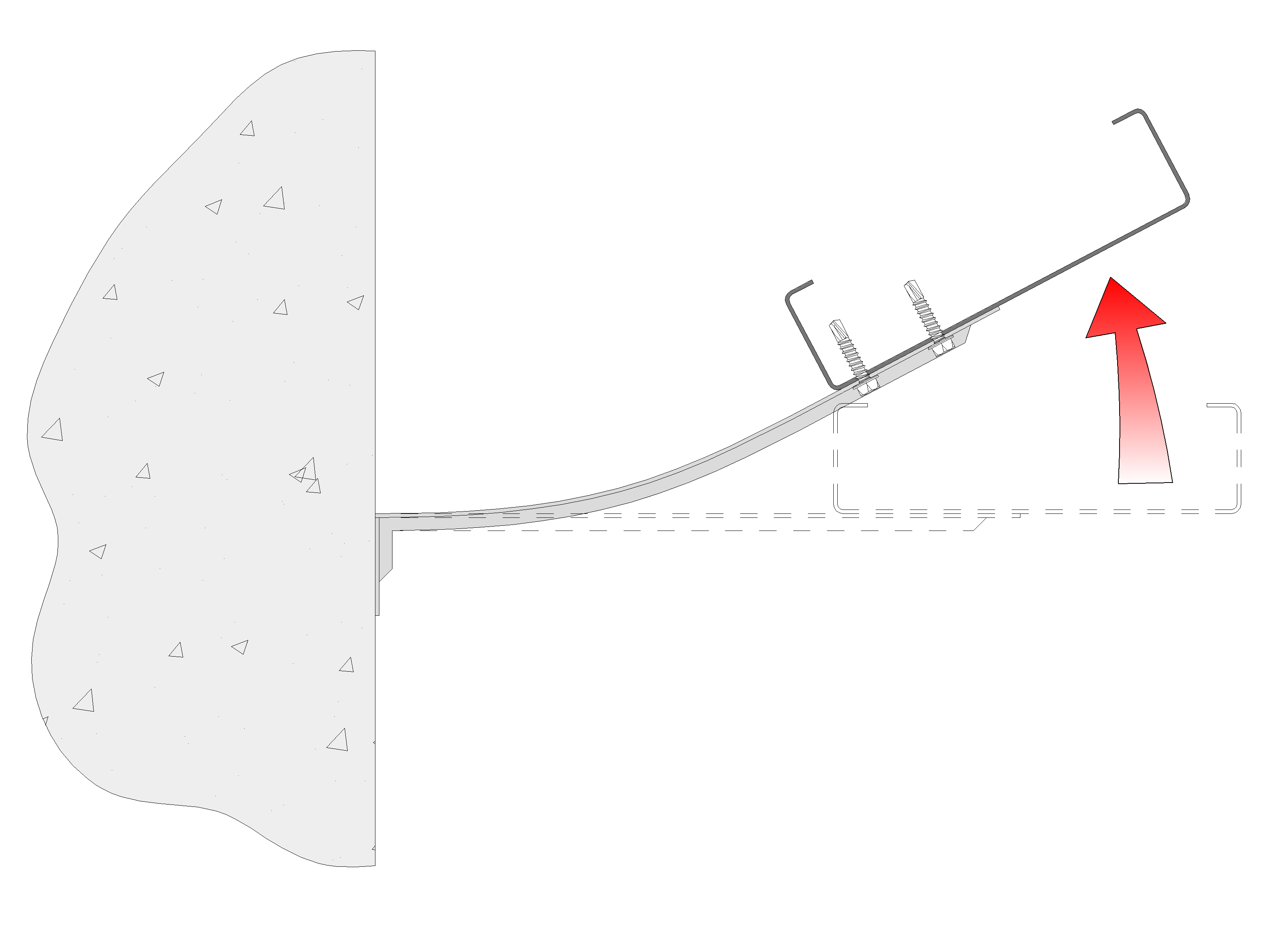
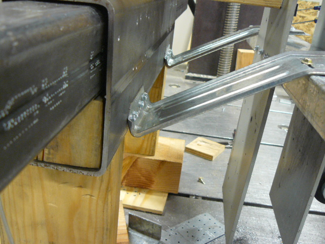
Also, the presence of sheathing materials, blocking, and other installation details will affect the rotational restraint between the stud and connector. In the case of a flexible system with little or no restraint, the connector will bend as a cantilever. However, if the curtain wall system provides rotational restraint, the connector may bend in double curvature, resulting in a higher in-plane allowable load.

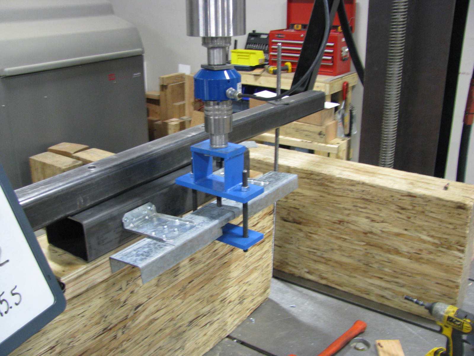
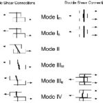
After some preliminary testing and extensive planning, we completed a little bit different test program to establish allowable loads for the multitude of possible design conditions. Instead of focusing on testing specific installations, we tested conditions to determine the capacity of critical failure modes – flexural yielding of the clip in bending, capacity of anchorage to the supporting structure, capacity of fasteners to the stud including prying, etc. Testing also simulated both cantilever bending and double curvature bending. Using this data, we were able to tabulate allowable loads for a wide range of installations (http://www.strongtie.com/ftp/letters/generic/L-CWC_F1LOADS.pdf)

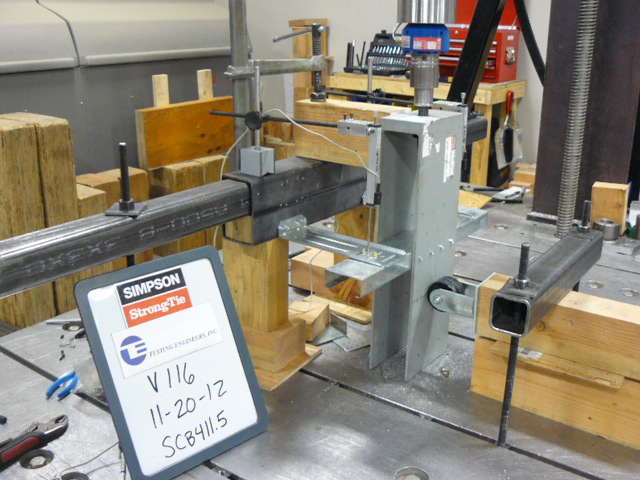
Aren’t we done testing yet? Nope. Next we ran cyclic load tests to confirm ductile behavior (which the tests did confirm). These tests required a new setup that allowed us to both push down and pull up. And if that wasn’t enough, we have even dabbled with tests where we are attempting to define system behavior including restraint provided by sheathing.
As you can see, we are continually performing tests to better understand the behavior of our products. This allows us to offer unparalleled technical data for designers and building officials. In some cases, testing is never really “done yet.”
How important to you is product testing that represents a range of field conditions and design assumptions? Let us know by posting a comment.
– Paul
What are your thoughts? Visit the blog and leave a comment!


From my perspective as a construction engineer, there’s no such thing as too much testing. Knowing how things fail helps to improve them. Knowing how they behave under loading helps to improve the testing methodology. Improving the testing methodology leads to better and more realistic test results. The cycle continues. Perhaps at some point for some components we simply run out of new data obtained from the testing. Until someone discovers a slightly different application.
Looks like the loads you are testing for are not what is important. The tie back load with lateral and vertical movement capacity is what is impotant. We do not want the panel to fall off. Keep on testing.
We did the out-of-plane and vertical load testing and published those loads first, since those are the loads designers are most commonly addressing. The in-plane, F1, loads were the next priority and were challenging tests as far as determining proper boundary conditions in the lab.
David K poses an interesting question. What is the
tie-back (out-of-plane) capacity during (or subsequent to) the in-plane movement? That is to say, not the in the initial state, but for example after cycling.
For combined in-plane plus out-of-plane loading, our experience with connectors has shown that a simple unity equation works very well although can be too conservative. For hurricane ties, we did an extensive test program at Clemson University to get a better (less conservative) solution for multiple simultaneous loads on a connector. A similar program with curtainwall clips may yield similar results.