


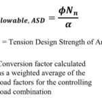
Structures and connections can be designed either using Allowable Strength Design (ASD) method or Load and Resistance Factor Design (LRFD) method. In the ASD method, the allowable strength is calculated by dividing the nominal strength by a safety factor. In the LRFD method, the design strength is calculated by multiplying the nominal strength by the resistance factor. In design, the adjusted ASD design value is compared to a calculated load or stress. As long as the adjusted ASD design value exceeds the calculated load of stress, then the ASD design value is judged safe. In LRFD design, the nominal strength is equated to factored loads. If the factored strength is greater than the factored loads, then the design can be accepted. ASD is the more common method adopted in the professional world.
LRFD is relatively new to wood design. Prior to 2005, the National Design Specification for Wood Construction (NDS) was based on allowable stress design (ASD). In the 2005 edition, the American Wood Council incorporated Load and Resistance Factor Design (LRFD) into the NDS. To this day, most wood design in the US relies on ASD, but the use of LRFD is becoming more common. On the other hand, the steel design industry already uses the LRFD philosophy for design, and for that reason, design values for steel self-drilling tapping screws are offered in both ASD and LRFD.
The published design values for Simpson Strong-Tie wood fastener products are in ASD format and the allowable loads are generally shown at a load duration factor of CD = 1.0. The reference design loads listed shall be multiplied by all adjustment factors listed in Table 10.3.1 of NDS 2012 to determine adjusted design values. The load tables are listed in ASD format because ICC-ES acceptance criteria, such as AC233 (Alternate Dowel-type Threaded Fasteners) and AC120 (Wood Frame Horizontal Diaphragms, Vertical Shear Walls, and Braced Walls with Alternate Fasteners), that are used to qualify structural wood screws do not address the development of LRFD values for wood screws. However, one can establish the nominal strength values for fasteners from reference ASD design values for use in LRFD format by following the instructions of NDS (2012), Table 10.3.1. Reference design values shall be multiplied by the format conversion factor KF as specified in Table N1 of NDS 2012. Format conversion factors adjust reference ASD design values to LRFD reference resistances. They are also multiplied by the resistance factor, Φ as specified in Table N2 and Time Effect Factor, λ as specified in Table N3.
For e.g., the table below lists the ASD allowable shear loads for SDWS screw in Douglas Fir-Larch and Southern Pine Lumber:

For the SDWS22300DB screw with a wood side member thickness of 1.5 inches, the allowable shear load is 255 lbs. with a wood load duration factor of CD = 1.0. To convert this to an LRFD load, refer to table 10.3.1 of NDS 2012 and Appendix N, Tables N1, N2 and N3. Per Table 10.3.1 we need to multiply the reference load with format conversion factor KF, resistance factor, Φ and time effect factor, λ From the Table N1, the format conversion factor KF for connections is 2.16/Φ. From Table N2, for connections Φ=0.65. Let us assume a λ of 1.0 from Table N3. The LRFD load is calculated by multiplying the allowable shear load with the factors above.
LRFD load = Allowable shear load (at a load duration factor of CD = 1.0) x KF x Φ x λ
LRFD Load = 255 x (2.16/0.65) x 0.65 x 1.0 = 551 lbs.
For steel self-drilling, self-tapping screws, the omega and resistance factors used for calculating ASD and LRFD loads are based on American Iron and Steel Institute (AISI) standard S100. For Simpson Strong-Tie steel self-drilling, self-tapping screws the load tables are listed in both ASD and LRFD format.
If the screw connection capacities are calculated based on tests, the ASD values are calculated by dividing the tested nominal strength which is the average of the ultimate strength values from all the tests with the safety factor, Ω. For LRFD load, the tested nominal strength is multiplied by a resistance factor, Φ. When tests are performed for evaluating the connection capacities, the safety factor, Ω and the resistance factor, Φ are evaluated in accordance with Section F of AISI S100. Simpson Strong-Tie derives the LRFD values for steel self-drilling, self-tapping screws in LRFD format because this is part of ICC-ES AC118 (Tapping Screw Fasteners). See evaluation report ICC-ES ESR 3006 for examples of ASD and LRFD design values for the same fastener products.
If the screw capacities are determined based on the calculated nominal strength, the ASD loads and LRFD loads are determined based on Section E4 of AISI S100. For e.g., the table below lists the ASD loads and the LRFD loads based on calculations for #14 x 1” screw.

From the table, for 33 mil (20ga) steel to 33 mil (20ga) steel shear connection, the calculated nominal shear strength is 600 lbs.
Nominal Strength = 600 lbs.
From Section E4, the safety and resistance factors for connections are:
Ω = 3.0
Φ = 0.5
ASD Load = Nominal Strength/Ω = 600 lbs./3.0 = 200 lbs.
LRFD Load = Nominal Strength x Φ = 600 lbs.x 0.5 = 300 lbs.
Now that you know the basics of ASD and LRFD, make sure you choose the one best suited for your specific material and construction application. If you have ideas for which of our products you would like to see in ASD and LRFD loads, be sure to let us know!


Hello,
If a Reference Design Value is adjusted for a wind/seismic LRFD application, is the intention of the ASD Load Duration Factor (C_D) captured during this adjustment?
Reference Design Values are based on normal load duration (10 years). Following ASD, the Load Duration Factor adjusts these values to account for a wind/seismic condition (10-minute duration).
However, adjustment from ASD to LRFD using the Format Conversion (K_F), Resistance (Phi), and Time Effect (Lambda) Factors seems to be based on the condition of normal load duration.
Should the Load Duration Factor be applied to a Reference Design Value before LRFD factors are applied to resolve the Adjusted Design Value for a wind/seismic condition?
Thanks,