

This blog has described how we load rate different products based on test standards, which are covered under various ICC-ES Acceptance Criteria, or ACs. The first was a post on wood connectors (AC13), then holdowns (AC155), threaded fasteners (AC233) and cast-in-place anchors for light-frame construction (AC398 and AC399). I realized today that I have never talked about how we test and load rate connectors for cold-formed steel.
But first, a confession – it has taken me many years to stop calling it “light-gauge steel.” When I started designing with cold-formed steel, I called it “light-gauge” because I had a binder of design information put together by the Light Gauge Steel Engineers Association. Advocates for CFS felt that “light-gauge” may make people think “weak” or “non-structural,” and that perception would limit the use of cold-formed steel in construction. So there was a deliberate effort to banish the word light-gauge and replace it with cold-formed steel, or CFS. I still slip every once in a while.
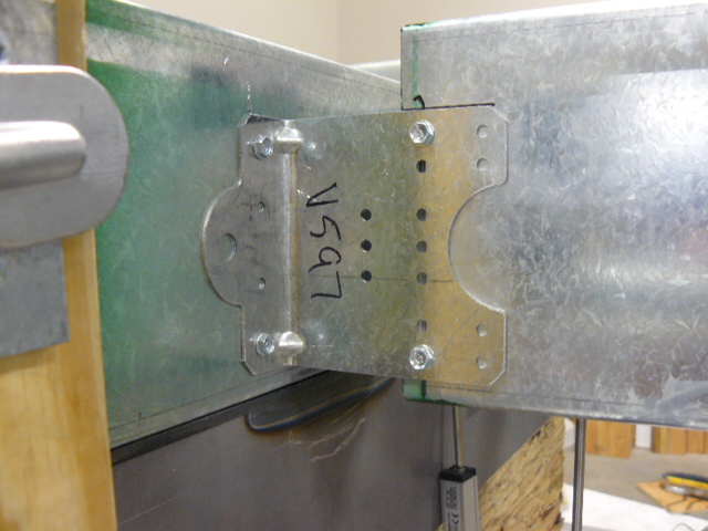
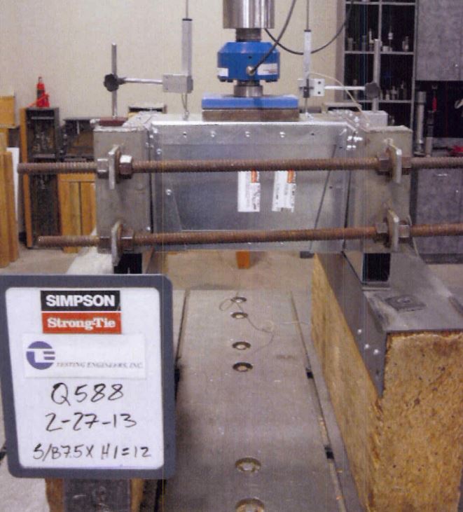
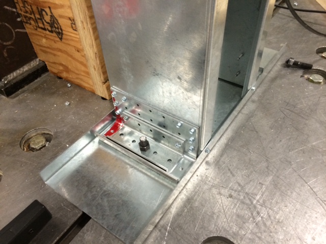
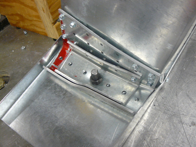
Connectors for light-gauge, ahem, I mean cold-formed steel members are covered under ICC-ES AC261 – Acceptance Criteria for Connectors Used with Cold-formed Steel Structural Members. The physical testing for cold-formed steel is similar to wood connectors. Build a setup representative of field conditions, apply load till failure and measure the load and deflection data. Both wood-to-wood and CFS connectors have a service limit state of 1/8” deflection.
Strength data for CFS connectors is analyzed much differently, however. Wood connectors generally use a safety factor of 3 on the lowest ultimate load (or average ultimate if six tests are run). We are often asked what the safety factor for CFS connectors is.
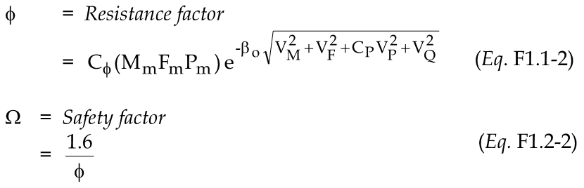
AISI S100 Chapter F details how to determine design strengths for tested CFS products. The design strength is the average test value, Rn, multiplied by an LRFD resistance factor, Φ, or divided by an ASD safety factor, Ω. Determining the resistance factor or corresponding safety factor is based on a statistical analysis dependent on several variables. This is similar in concept to how embedded concrete connectors tested to AC398 or AC399 are evaluated, which I discussed in this post.
I don’t want to get too deep into the Greek letters involved in the calculation. The factors that affect the allowable load calculation are type of member tested, variation in the test values, type of manufacturing, and number of samples tested. One factor that has a large impact on the calculation is the target reliability index, βo. In connector testing, this factor is 2.5 if the structural member (joist, stud, track, etc) fails and 3.5 if the connection fails. The net result is a higher safety factor for test values limited by the connection, and lower safety factors if the structural members governed the test load. Typical safety factors for CFS connectors are 1.8 to 2.0 where the failure mode is in the structural members and 2.2 to 2.9 for tests where the connection failed.
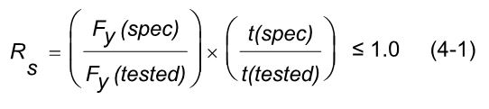
AC261 has a reduction factor, RS, which is used to adjust test values if your steel strength and/or steel thickness are over the specified minimum. CFS test setups often use different steel in the joist, header and the connector. Reductions are calculated based on the tested and specified strength and thickness for each member. The lowest reduction is used to adjust the test values.
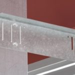
One additional complexity in CFS testing is the multiple gauges of steel which must be evaluated. This requires more CFS test setups than a comparable wood connector would require. In the end, we have what we are really after. Design loads that specifiers can be confident in.


Thanks sir that’s great information
It’s great help
Sir can I get a basic design for cold formed steel elements in soft or some informative docs which enables me to go in depth in cold formed steel design
My email: shams.sheenwari@gmail.com
Thanks sir
The Cold-Formed Steel Engineers Institute has a number of publications available on their website:
http://www.cfsei.org/publications
Hi Paul,
My name is Panha. I am a graduated civil engineering, currently working in a facade company. at the moment I am asked to design a stainless steel beam to support the window frame. could please help me to provide some example design calculation for the stainless steel beam?
I don’t have a design example that would be useful. You might try this:
https://www.aisc.org/store/p-2301-design-guide-27-structural-stainless-steel.aspx
“Design Guide 27, Structural Stainless Steel, provides guidance for the design of structural stainless steel. It is written for engineers experienced in the design of carbon steel structural components but not necessarily in the design of stainless steel structures, and is aligned with the design provisions in the 2010 AISC Specification for Structural Steel Buildings. It applies to the design of structural hot-rolled or welded open sections such as I-shaped members, channels, and equal-leg angles. It also applies to rectangular and round hollow structural sections (HSS). The guidance provided is applicable to austenitic, duplex and precipitation hardening stainless steel structural sections with thickness 1/8 in. (3 mm) and greater. Major topics covered are material behavior and selection, cross-section design, member design, connections, and fabrication. Design Examples are also included.”