

Back in the year 2000, the U.S. Department of Defense (DoD) was charged with incorporating antiterrorism protective features into the planning, design and execution of its facilities. The main document developed to meet this requirement is the Unified Facilities Criteria “DoD Minimum Antiterrorism Standards for Buildings” (UFC 4-010-01). The current version was published in October 2013. This document covers what is most commonly referred to as “blast” design.
All DoD inhabited buildings, billeting (military housing) and high-occupancy family housing projects are required to comply with this standard. The most common projects incorporating cold-formed steel framing are for the military branches (including National Guard and Reserve components). Notable exceptions are: low-occupancy buildings (11 occupants or fewer), transitional structures (with intended life cycles of five years or less), standalone retail establishments and parking structures. A complete list of excluded buildings types is located in chapter 1-9 of UFC 4-010-01.
General structural requirements for DoD projects are provided in the UFC 1-200-01 standard. The current model building code referenced is the 2012 IBC. Specific structural design criteria are also listed for all major military bases. UFC 4-010-01 specifically states that its requirements do not supersede the structural requirements of UFC 1-200-01. Basically, three lateral designs are required for all DoD projects: wind, seismic and blast.
The main design strategies employed by UFC 4-010-01 are to maximize standoff distance, prevent progressive collapse and minimize hazardous flying debris. Progressive collapse avoidance is addressed by UFC 4-023-03. The main criterion to note is that it is only required in structures of three or more stories in height.
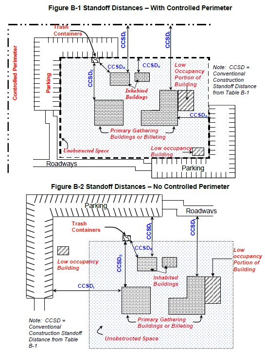
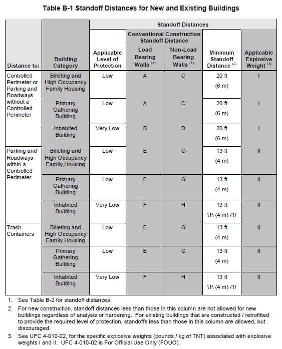
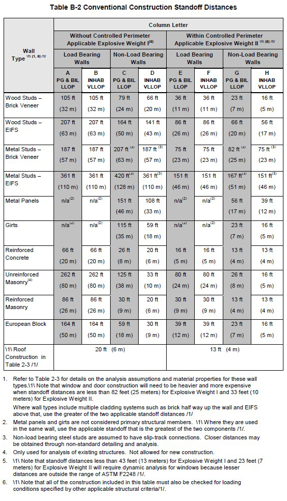
UFC 4-010-01 tables B-1 and B-2 provide the conventional standoff distances and minimum standoff distances for a building based on its construction type and building category. The conventional standoff distance is where conventional construction may be used for building components other than windows and doors without a specific analysis of blast effects. The minimum standoff distance is the smallest permissible distance allowed regardless of any analysis or construction hardening.
To minimize hazardous flying debris, two basic components are addressed: typical wall framing and opening support framing. UFC 4-010-01 Table 2-3 provides the allowable height for cold-formed stud typical wall framing based on material, spacing, support conditions and supported weight.
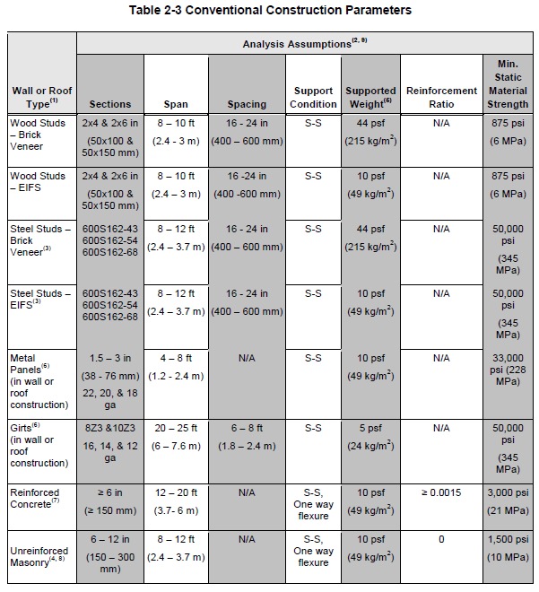

For both brick veneer and EIFS cladding, the maximum allowable height is 12″-0″. Note that 50 ksi stud material is required to meet these requirements. There is no similar strength requirement for connections.
For framing that meets both the conventional standoff distance and allowable member height, NO further blast analysis is required. For framing that does not meet either the conventional standoff distance or allowable member height, additional blast analysis IS required. The support framing (head/sill/jambs) for windows and skylights ALWAYS requires additional blast analysis. Per section B-3.3.3 of UFC 4-010-01, the support framing for doors, glazed or solid, is not required to be analyzed for blast. Doors are designed to remain in their frames and not become hazards to building occupants. Sidelights and transoms that are included within the door assembly are also not required to be analyzed for blast. There are exclusions provided for unoccupied areas of buildings, such as exterior stairwells and exterior walkways. Personal experience with the U.S. Army Corps of Engineers Protective Design Center (USACoE PDC) has shown that unoccupied attic areas are also allowed to be excluded from the provisions.
Two “levels of protection” are provided for in the UFC 4-010-01. Only Low Level of Protection (LLOP) and Very Low Level of Protection (VLLOP) buildings are addressed. Low Level of Protection allows for moderate damage with collapse being unlikely and having the potential for serious but not fatal human injury. Very Low Level of Protection allows for heavy structural damage with progressive collapse unlikely and having serious human injury likely with potential fatalities. Any projects that require a higher Level of Protection designation must be referenced elsewhere. The project appropriate “Level of Protection” is provided in UFC 4-01-01 Tables B-1 and B-2.
UFC 4-010-01 allows for two basic analysis methods for performing blast design, static analysis and dynamic analysis. Static analysis can be performed with the aid of the Simpson Strong-Tie® CFS DesignerTM software, while dynamic analysis must be performed with the “Single-degree-of-freedom Blast Effects Design Spreadsheet” (SBEDS) obtained from the USACoE PDC. Generally, dynamic analysis will provide lighter members than static analysis.
Static Analysis Method
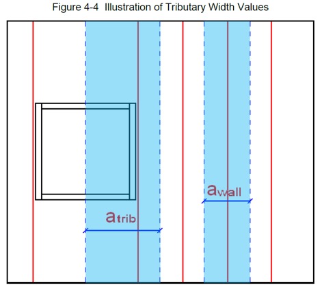
Static analysis of “punched” openings (framed with head and sill members and supported by jamb studs) is only allowed to be performed if the conventional standoff distance is met. Ribbon windows, aluminum curtainwalls, storefronts, etc., are required to be designed by the dynamic analysis method. The “punched” window supporting structure is to be designed to account for the increased tributary area representing the area of the window and the walls above and below it. These supporting elements must have moment and shear capacities greater than the calculated conventional wall capacities multiplied by the applicable tributary area increase.
 For example, if the tributary area of the “punched” opening is three times the typical full-height stud spacing, three members are required for the jamb stud assembly. An alternate member with moment and shear capacities greater than or equal to three times the typical full-height members’ capacity can also be used. UFC 4-01-01 section B-3.1.4.1 states that connection loads shall be determined based on the increase in member shear capacity. It makes a difference which members are chosen for the jamb stud assembly, as the connection must be designed for the shear capacity of that specific assembly. Per UFC 4-010-01 section B-3.1, the connectors themselves are designed using LRFD methods with a Load Factor of 1.0. The resistance factor for bending is allowed to be 1.0, while the resistance factors for other failure modes remain per the AISI code (Shear = 0.95). Per UFC 3-340-02 section 5-47, when LRFD values are not published for connectors, a value of 1.7 times the allowable strength is permitted. Published LRFD strengths already have the appropriate resistance factors incorporated. Simpson Strong-Tie publishes LRFD values for all of its connectors.
Dynamic Analysis Method
As mentioned above, dynamic analysis is performed with the SBEDS spreadsheet tool provided free of charge by the USACoE PDC. There is a simple approval process to undergo in order to receive a software key for the program. The general inputs for the program are fairly straightforward. There is a list of standard preset stud shapes that can be selected. The list is not comprehensive, but shape property inputs are provided for “user defined” members.
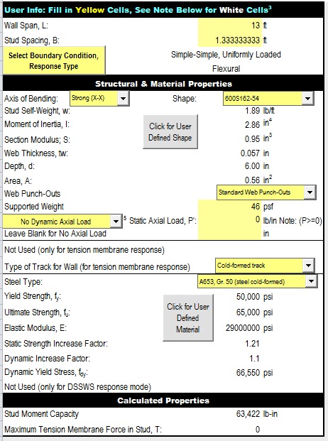
The SBEDS spreadsheet is formatted to analyze single-span wall framing. For analyzing opening support framing, the stud spacing and supported weight will have to be adjusted. Per PDC TR-10-02, the stud spacing is to be figured the same way as in the static analysis method. The spreadsheet analyzes the entire wall at one supported weight, so this will also have to be adjusted to account for the differing weights of the building cladding and glazing, providing an average support weight. For EIFS cladding, all weights are typically assumed to be the same (6 psf actual). For brick veneer (46 psf actual), the supported weight must be reduced to account for the lower weight of the glazing (6 psf actual). The wall span will need to be adjusted to the actual length of the head and sill members.
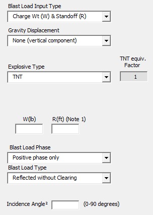
The blast parameters are input as “Charge Weight & Standoff.” The appropriate project explosive weight is referenced from the UFC 4-010-02 standard. This publication is authorized only to U.S. Government agencies and their contractors. Approval must be obtained from the USACoE PDC to obtain this document. The standoff distance is entered as the project-specific standoff distance. The Incidence angle can be calculated as the arc tangent (ATAN) of the height to the center of the opening divided by the actual standoff distance. The remaining typical blast parameter inputs are shown below.
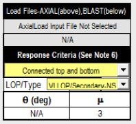
The typical response criteria inputs are shown below. Typically stud framing is required to be “connected top and bottom.” There is an option to select “Top Slip Track,” but personal experience has shown that this option does not pass the analysis. There are two options provided with the “Level of Protection” type. “Primary” would be selected for load-bearing projects, while “Secondary-NS (Non-Structural)” would be selected for curtainwall-type projects.
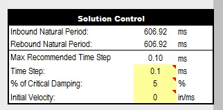
For the Solution Control inputs, the main check is to verify that the inputted time step matches the calculated recommended time step. The calculated value will change when various other inputs are changed. The “% of Critical Damping” can be entered as 5% for CFS framing, per the spreadsheet cell comment. The “Initial Velocity” is entered as zero, also per the spreadsheet cell comment.
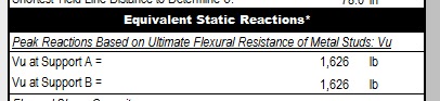
Connections are designed to meet or exceed the “Peak Reactions Based on Ultimate Flexural Resistance” value given in the SBEDS output. Per UFC 4-010-01 section B-3.1, design is done per LRFD methodology with Load Factors equal to 1.0. The Resistance Factor for bending is allowed to be 1.0, while the Resistance Factors for other failure modes are per the AISI code (Shear = 0.95). Published LRFD strengths already have the appropriate resistance factors incorporated. The conservative assumption would be that shear controls the failure, and an increase in the LRFD Resistance Factor is not appropriate.
Per UFC 3-340-02, there are additional increases in connection strength that can be taken for dynamic blast design. The Strength Increase Factor (SIF, a.k.a. Static Increase Factor or Average Strength Factor) considers that yield stresses for all CFS materials provided are typically higher than the minimum yield stresses required by ASTM A446 (replaced by ASTM A653) steel. Per section 5-12.1, the SIF is listed as 1.21 for all CFS framing but only applies to the yield stress (Fy). Any calculations involving the ultimate stress (Fu) value are not allowed to be increased. The SIF also does not apply to fasteners (screws, bolts, PAFs, welds, etc.). The Dynamic Increase Factor (DIF) considers the strain-rate effects from rapid blast loading. Per section 5-34.2, this increase is listed as 1.10 for all CFS framing and per UFC 4-0-010-01 section 4-7, 1.05 for welds. Conservatively, it is assumed that the DIF equals 1.0 for all other fasteners (screws, bolts, PAFs, etc.).
Dynamic Connection Strength = (LRFD Strength)*(SIF)*(DIF)
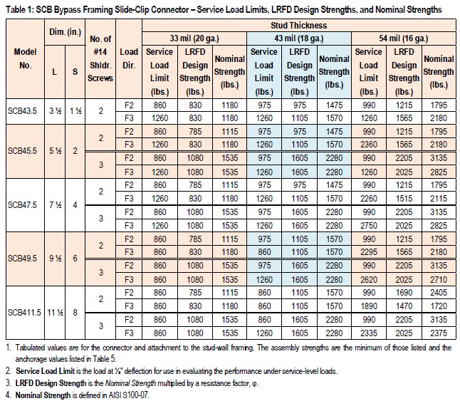
For example, per Table 1 given below (reference Simpson Strong-Tie® engineering letter L-CF-CWCLRFD15), the SCB45.5 Bypass Slide Clip (3 screws to 16 ga. material) has a Dynamic Connection Strength = (2,025)*(1.0)*(1.10) = 2,227.5 lb., meeting the required reaction shown above.
Again per UFC 3-340-02 section 5-47, when LRFD values are not published for connectors, a value of 1.7 times the allowable strength is permitted.
Dynamic Connection Strength = 1.7*(Allowable Strength)*(DIF)
Simpson Strong-Tie publishes LRFD values for all of its connectors.
References:
UFC 4-010-01: February 9, 2012 (Change 1 – October 1, 2013)
UFC 3-340-02: December 5, 2008 (Change 2 – September 1, 2014)


What I find interesting but also somewhat disappointing is that the DOD has done full scale load testing on ICF walls more than 10 years ago but they are not even mentioned in the current standards. The tests they did showed that the blast absorbing capacity of the insulating forms used in ICF walls enabled most walls to resist a sizable blast with standard reinforcing, thus adding little cost for the blast protection provided.
http://icfresource.com/pdf/explosives-tests.pdf