In time for spring and summer 2017 construction projects, Simpson Strong-Tie has launched the newest version of the Strong-Wall Shearwall Selector for use with engineered design. The latest release is an easy-to-use Web-based application (that’s right, no software to download) that has been updated to comply with the 2015 IBC and now provides solutions for all three Strong-Wall Shearwall types: the Steel Strong-Wall® shearwall (SSW), the Strong-Wall wood shearwall (WSW) and the wood Strong-wall shearwall (SW). If you are familiar with the Strong-Wall Shearwall Selector, you can begin using the web application immediately. For those of you who would like to know more about the web app, please read on.
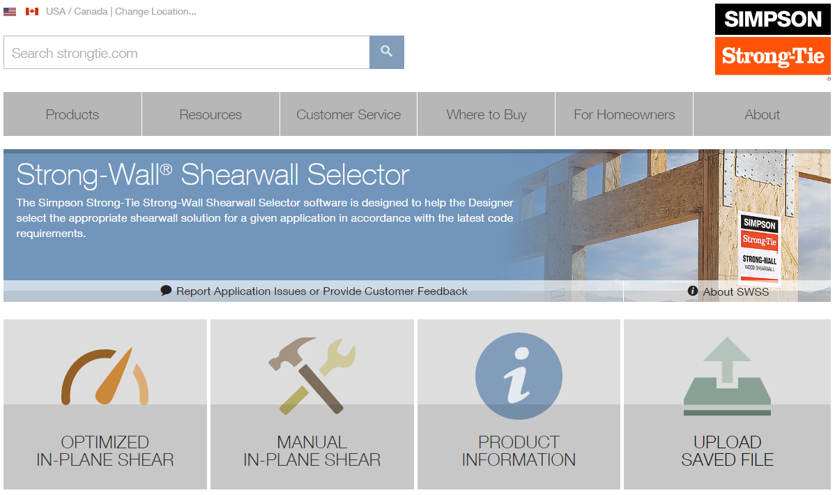 The Strong-Wall Shearwall Selector was created to help the Designer select the appropriate shearwall solution for a given application in accordance with the latest building code requirements. By performing a technical analysis, the web app provides actual drift and uplift values for a wind or seismic design shear load.
The Strong-Wall analysis also considers simultaneous, vertically applied load. In cases of multiple walls in a line, the program performs a rigidity analysis and determines the actual distributed shear to each wall. When walls are stacked in a two-story configuration, the program evaluates cumulative overturning effects to ensure that the wall, anchor bolt and anchorage to the foundation are not overstressed.
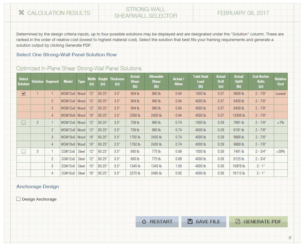
The web app provides two modes for generating an engineered solution: Optimized In-Plane Shear or Manual In-Plane Shear. The Optimized mode lists several possible solutions for the selected criteria in the order of cost. The Manual mode evaluates any number or combination of walls for adequacy based on the selected criteria. The Designer has the option to generate an Anchorage Solution based on foundation type. Once a solution has been selected, the web app will generate a pdf output. Files can be saved and reused for future designs.
Input Variables Within the Two Solution Modes:
Job Name: Enables the Designer to provide a specific job name for a project.
Wall Name: Enables the Designer to provide a name for each wall line in a project.
Wall Type (Manual Only): Solutions are provided for the selected Strong-Wall panel type: SSW, WSW, SW
Application: Defines the proposed application (use) of the wall. The choices are for walls in a garage front, a standard wall on concrete, on a first-story wood-floor system, in a second-floor non-stacked application, in a two-story stacked application, or in a balloon-framed application. For the Steel Strong-Wall® (SSW) and Strong-Wall wood shearwall (WSW), garage front may be chosen with or without the portal kit. Higher shear capacities are available when the portal kit is used.
Cold-Formed Steel Construction (CFS): This option appears for “Garage Front,” “Standard Wall on Concrete,” “First-Story, Raised-Floor System” and “Two-Story Stacked” applications. If the check box is enabled, the program will provide the proper Steel Strong-Wall model for use in CFS construction.
1st Story Wall on Wood Floor (SW – Wood Strong-Wall Shearwall only): This check box only appears if a Two-Story Stacked application has been selected. If enabled, the program will then assume the lower story wall, in a stacked application, is installed on a wood floor.

Design Criteria:
The design criteria may now be selected. Drop-down menus provide options for Applicable Building Code, load type, concrete strength, wall height, wall geometry and floor depth (if applicable). Entry fields may be used to indicate shear- and axial-loading information. The following applies once the appropriate design criteria have been input: If Optimized In-Plane Shear has been selected, the possible solutions are displayed in the Strong-Wall Panel Solutions list. If Manual In-Plane Shear has been selected, a list of available walls will be displayed in the Strong-Wall Panel Solutions list, any of which may then be selected and added to the desired Solution.
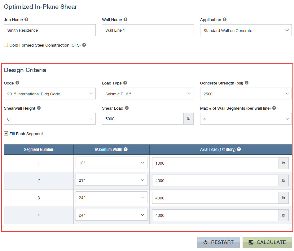
Code: Wall solutions are provided in accordance with the requirements of the 2015 and 2012 International Building Code (IBC). Code reports may be found here.
Load Type: This criterion defines whether the input shear load is due to wind or seismic forces. The Designer must input the controlling load. The appropriate seismic “R” values are provided for the selected code.
Concrete Strength: Concrete strength may be selected based on specific project conditions. Default concrete strengths of 2500 psi, 3000 psi, 3500 psi, 4000 psi and 4500 psi are provided in the drop-down menu. Note that for shearwall selection purposes, concrete strengths are only applicable to Steel Strong-Wall® (SSW) and Strong-Wall wood shearwall (WSW). In some cases, lower anchorage forces may be obtained with a higher concrete strength. The concrete strength is also used for determining the anchorage tension capacity.
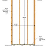
Wall Height: Select the nominal wall height. Actual wall heights are shown under the “H” column of the Solution(s).
Shear Load: Input the total Allowable Stress Design (ASD) design (demand) shear load along the wall line. Include all appropriate load factors on the shear load prior to input for the load combination under consideration. For Two-Story Stacked applications, input the story shear at each level and the program will evaluate the first-story walls for the total shear.
Floor-Joist Depth: This option appears only with first-story raised-floor systems and two-story
stacked applications. Floor-joist depth affects the capacity of Steel Strong-Wall panels installed on wood floors. Floor-joist depth is also considered in the cumulative overturning evaluation of two-story stacked wood or steel walls.
Header Thickness: This option appears only when “Garage Front” applications and wall heights of 7′ or 8′ with a header on top are selected. This option is used to select the proper Wood Strong-Wall panel model (thickness) based on the nominal header thickness of 4″ or 6″.
Header Type: This option only appears when “Header Thickness” of 4″ is selected. It then provides an option to select a solid or double-ply header. Values for the wood Strong-Wall panels will slightly decrease if the double-ply header option is selected. Steel Strong-Wall panels with multi-ply headers are limited to wind designs and SDC A-C. .
Maximum Number of Wall Segments per Wall Line (Optimized mode only): Here the maximum number of available wall segments along a particular wall line is specified. The program enables the Designer to select a maximum of four wall segments per wall line (3 segments maximum for garage fronts.) For more wall segments per wall line, use the Manual mode.
Fill Each Segment (Optimized mode only): If this checkbox is disabled, then the minimum number of Strong-Wall shearwalls that can serve as solutions is provided up to the “Max # of Wall Segments” previously specified. If this checkbox is enabled, then the “Max # of Wall Segments” will always be used and filled with Strong-Wall shearwalls.
Segment Number, Maximum Width, Axial (lb.) (Optimized mode only): For each wall segment along a wall line, the maximum desired width of that segment and the axial load on that particular segment may be specified. The axial load is the total vertical upward or downward load assumed to act on the entire panel width. Include all appropriate load factors on the axial load prior to input for the load combination under consideration. A positive axial load reduces the actual uplift of the panel, while a negative axial load increases the actual uplift of the panel. The combined effect of the vertical axial load and overturning force is considered in the Steel Strong-Wall® (SSW) and Strong-Wall wood shearwall (WSW) solutions. The combined effect of the vertical axial load and overturning on the wood Strong-Wall (SW) shall be evaluated by the Designer so as not to exceed the “C4” and “T1” allowable vertical loads. Download an excerpt from our catalog for more information.
Axial Load 1st Story (Manual mode only): See discussion above on axial load. The axial load selected is initially applied on all Available Wall solutions. As walls are selected using the “Add” button, the axial load remains constant. If it is desired that each wall have a different axial load, then input the corresponding axial load value for the first wall and click on “Add Solution” to send it to the Selected Solution. Then enter the new axial load value for the next wall and continue this process until all the product selections are complete.
Maximum Wall Segment Width: This optional input limits the Available Strong-Wall Panels to the maximum width specified.
Available Wall(s) (Manual mode only): Based on the input Design Criteria, all Available Strong-Wall Panels and their allowable loads are listed as an option for selection. The Available Strong-Wall list is independent of the input shear load and instead represents a list whereby any quantity or combination of walls can be selected to resist the shear load.
Solution(s) and Output :
Possible Solution(s) (Optimized mode only): Up to four possible solutions may be displayed and are designated as Sol # (solution number) in the order of relative cost (lowest to highest material cost).
Selected Solution (Manual mode only):
Add Another Solution: Click on the “Add” button to select wall from Available Wall(s) list, which enters it into the Selected Solution list. You may also double-click on an Available Wall to add it to the Selected Solution.
Clear: Click on the “Clear Selected Solutions” button to entirely remove all previously selected walls in the Selected Solution.
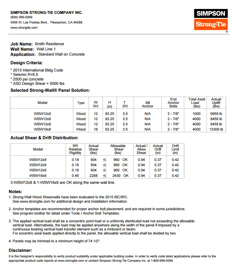
Generate PDF: This button creates a .pdf summary of the wall solution. Under Optimized mode, the output solution is created for the Sol# (solution number) that is highlighted. Under Manual mode, the Output is created for all walls shown in the selected solution list.
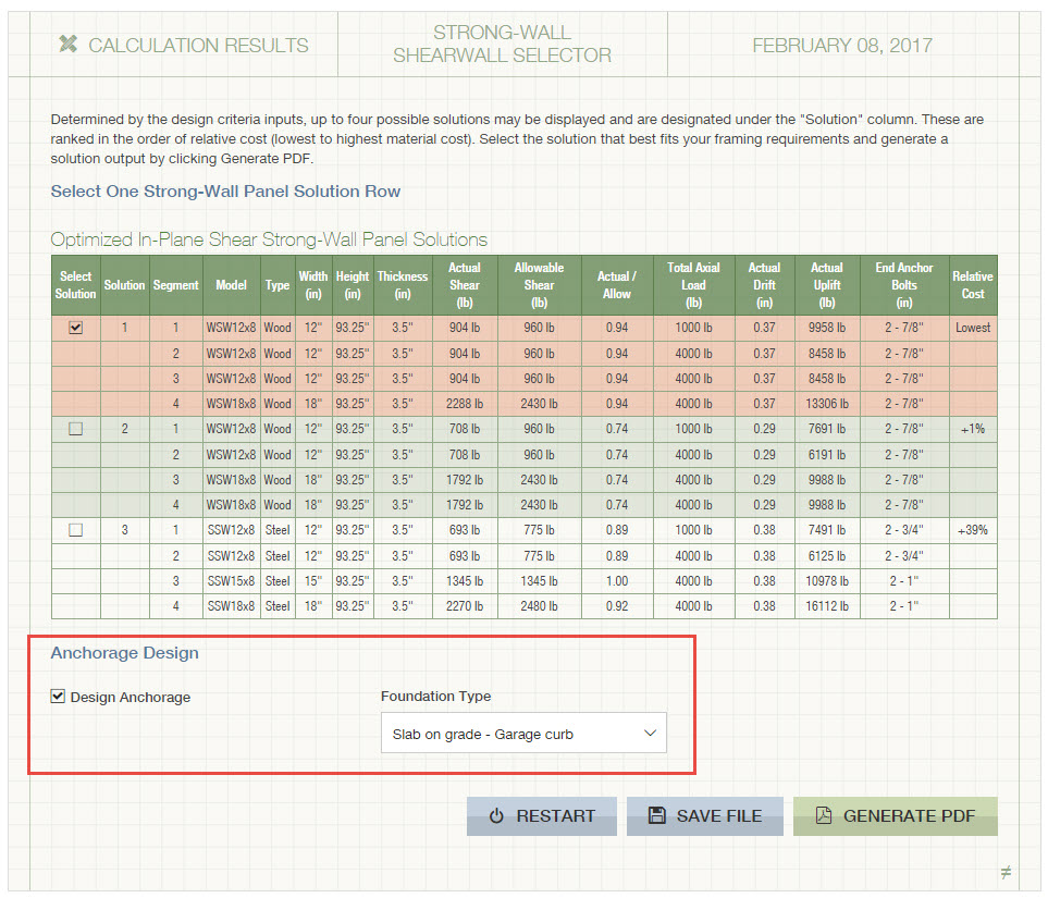
Design Anchorage: This option appears at the bottom of the page. If desired, enable the check box next to “Design Anchorage” and select Foundation Type. Anchorage design solutions will then be included in the PDF output.
Notes for Designer: Special notes related to the input variables are displayed in this window during the input process. When the Manual In-Plane Shear tab is selected, the Notes for Designer will indicate whether the Selected Solution is adequate to resist the applied design loads.
Anchorage Solutions and Output:
The Designer will have the option to generate an Anchorage Solution appended to the Strong-Wall shearwall solution. If desired, Select Foundation Type, then enable the check box next to Design Anchorage, and the .pdf file will be generated with the anchorage solution on subsequent pages. The designer can choose anchorage solutions based on foundation type for all shearwalls. The two foundation types are slab-on-grade and stemwall and are selected from a drop-down menu. Within each foundation type, the Designer can choose a specific footing type as follows:
Slab-on-Grade Footing Types: Garage curb, slab edge, brick ledge and interior.
Stemwall Footing Types: Garage front and perimeter.
Anchorage solutions are provided based on the shearwall solution(s) selected and the following design criteria: application, load type, actual uplift and concrete strength.
Anchor Bolt: Two anchor bolt solutions are available for the wood Strong-Wall®. They are the PAB7 and the SSTB, both of which are ASTM F1554 Gr. 36 material. The Steel Strong-Wall® uses a single anchor type, SSWAB, which may be either ASTM F1554 Gr. 36 or ASTM A449 (high-strength) material depending on the actual uplift. The Strong-Wall wood shearwall uses a single anchor type, WSW-AB, which may be either ASTM F1554 Gr. 36 or ASTM A449 (high-strength) material depending on the actual anchor tension.
Concrete Service Condition: This criterion refers to whether the concrete is determined to be cracked or uncracked based on analysis at service loads. See ACI 318 for the different reduction factors associated with cracked and uncracked concrete.
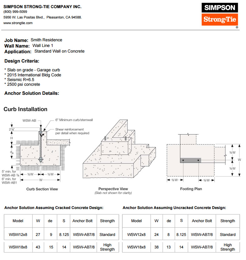
The anchorage design .pdf output summarizes all applicable design details including the footing type, minimum footing dimensions, anchor bolt and shear anchorage. The Designer is responsible for foundation design (size and reinforcement) to resist overturning, soil pressure, etc.
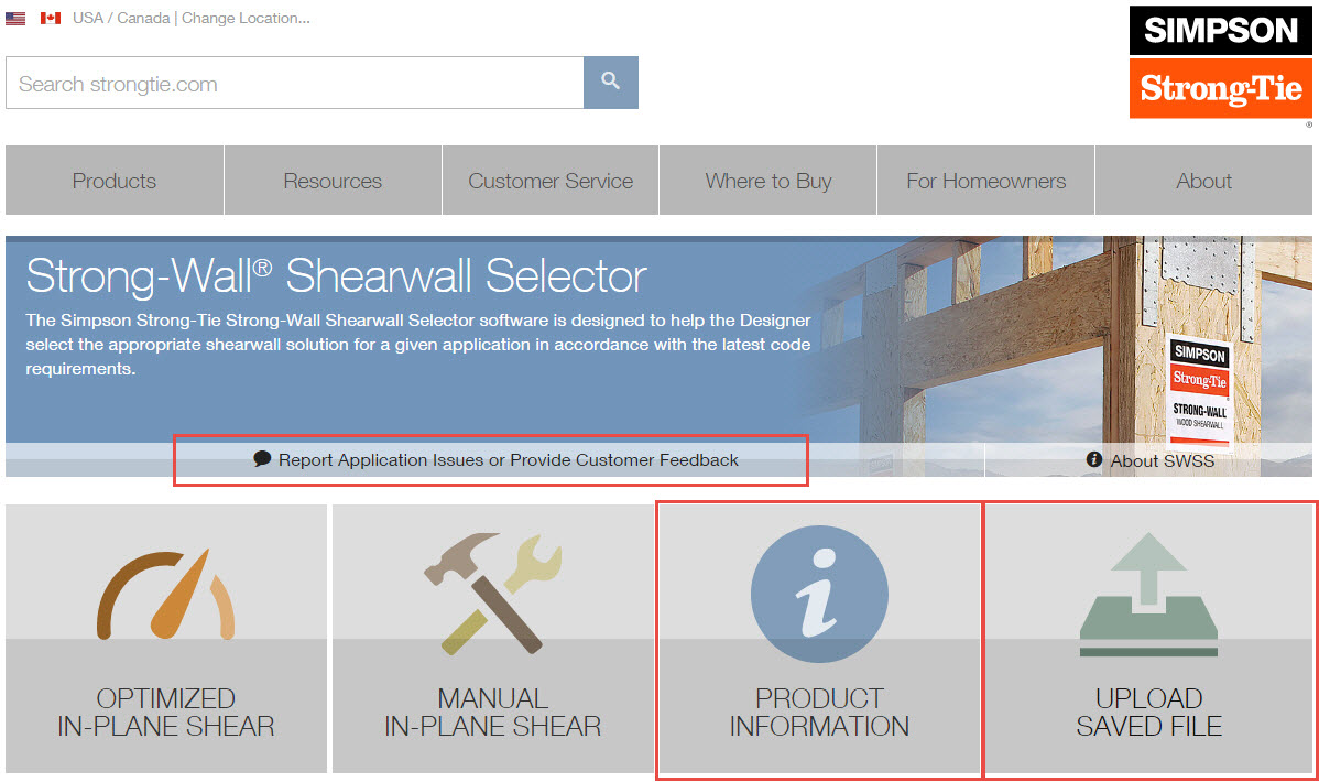
Product Information: Select for more product and application information.
Upload a Saved File: Designer can upload any previously used solution.
Report Applications Issues or Provide Feedback: If you are experiencing issues with the application or simply would like to provide feedback, please use this link. Simpson Strong-Tie values your feedback.
Get started on your next design project with the Strong-Wall® Shearwall Selector web application!