This week’s post was written by Bob Leichti, Manager of Engineering for Fastening Systems. Prior to joining Simpson Strong-Tie in 2012, Bob was an Engineering Manager covering structural fasteners, hand tools, regulatory compliance and code reports for a major manufacturer of power tools and equipment. Prior to that, Bob was a Professor in the Department of Wood Science and Engineering at Oregon State University. He received his B.S. and M.S. from the University of Illinois, and his M.S. and Ph.D. from Auburn University.
When test results don’t make sense, we start by eliminating causes of the problem. When our withdrawal test values came up low, we checked the load cell calibration, the specific gravity of the wood, the nail dimensions, even the units – everything was correct. So why were the nail withdrawal values so low? More wood, more nails, more tests – same results. Ultimately, we concluded that the withdrawal resistance of stainless-steel, smooth-shank nails is not well described by the withdrawal function in the 2012 NDS, section 11.2.3, equation 11.2-3.
Withdrawal Resistance
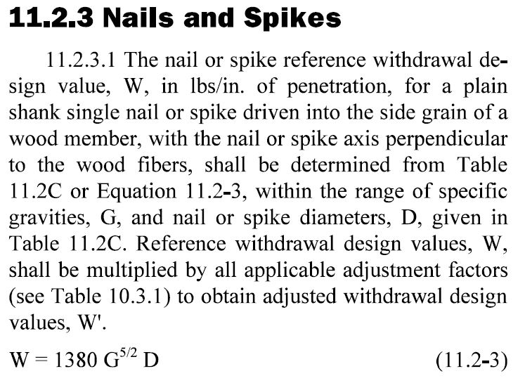
Withdrawal resistance for smooth-shank nails can be either calculated using the 2012 NDS nail withdrawal function or one can refer to the 2012 NDS Table 11.2C, which provides withdrawal design values for smooth-shank nails (common and box nails and common wire staples). The design function produces reference allowable withdrawal resistance in pounds of force per inch of penetration into the main member, and several research papers have shown that total withdrawal resistance increases linearly with penetration depth. In 2012, an equation was introduced for ring-shank post-frame nails. See 2012 NDS, section 11.2.3, equation 11.2-4.
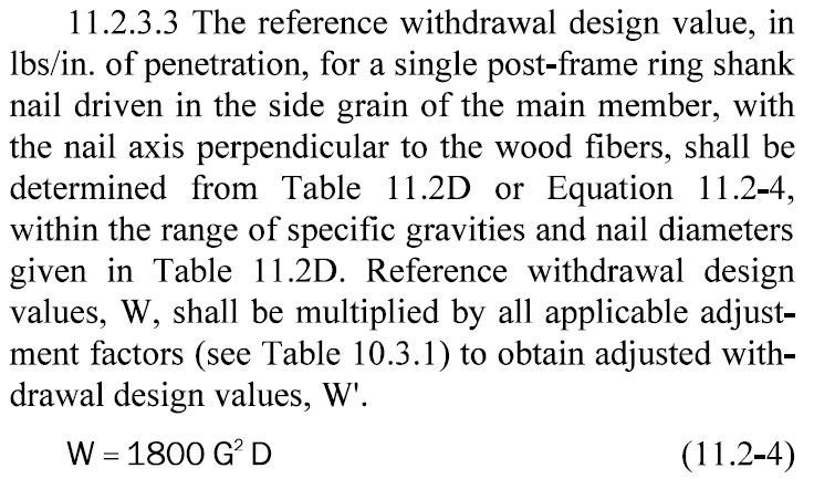
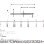
Post-frame ring-shank nails are described in ASTM F1667-11a, Table 45. The post-frame ring-shank withdrawal equation is the resistance per inch of threaded length penetration into the main member of the connection (including the tip). When you compare the results of the two withdrawal equations, it shows that the post-frame ring-shank nails are expected to have roughly twice the capacity of a smooth-shank nail of the same nominal diameter.
Withdrawal resistance is described by many researchers, the USDA Forest Products Laboratory’s Wood Handbook includes some good basic information, and the NDS Commentary describes some of the background for the design equations. The usual statement in research papers and references is that the subject nails are “bright,” but the unstated detail is that the nails are carbon steel. The research papers and the 2012 NDS are silent with respect to the effect of friction coefficient between the metal surface and the wood as it affects withdrawal resistance. Some unpublished work at the Forest Products Laboratory from the late 1940s with aluminum nails implies that there may be a withdrawal issue because the authors suggested that aluminum nails one size larger than carbon steel nails should be used when the nails are aluminum rather than steel or copper.
Have you seen the TechLine publication from the Forest Products Laboratory in August 2012? Sam Zelinka and Doug Rammer reported a study on withdrawal resistance of stainless steel nails (Zelinka, S. and D. Rammer. August 2012. Withdrawal Strength of stainless steel nails. TechLine, Forest Products Laboratory, USDA Forest Service, Madison, WI).
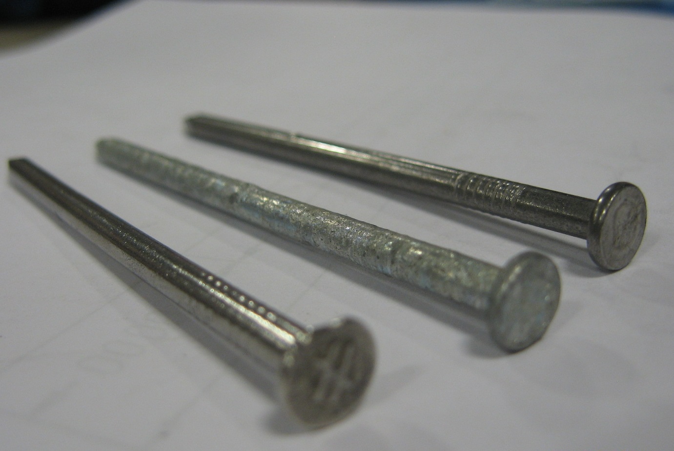
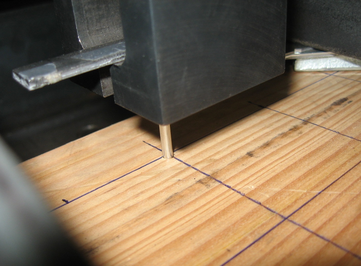
In summary, they designed an experiment where the sources of variation were wood specific gravity and nail diameter and the dependent variable was nail withdrawal resistance. The nails were “stainless steel” smooth-shank nails in three sizes to represent the range of structural nails, and one size of ring-shank nails. The 0.133-in. diameter nails in the study were made by three manufacturers. The wood represented the range of domestic species used for lumber, some hardwood, some softwood, from specimens with specific gravities from 0.31 to 0.76. The withdrawal tests were conducted following ASTM D1761. This test method requires that the nails are driven straight using the appropriate tool into the face grain of a conditioned wood prism and then the embedded nails are loaded in withdrawal. Withdrawal resistance is expressed in terms of resisting force per inch of penetration, which includes the tip.
Zelinka and Rammer compared their test results to predicted maximum loads. Table 1 is reproduced from the Zelinka and Rammer TechLines article.
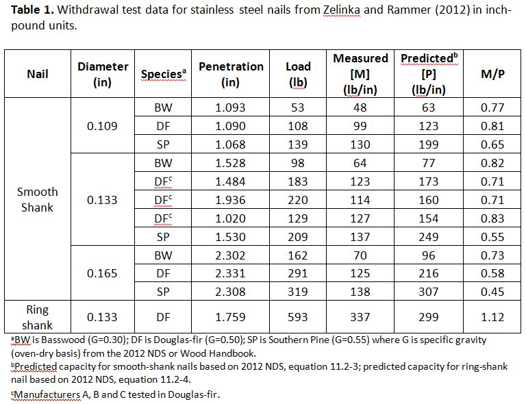
There are two significant trends in the data. The first is that for all three smooth-shank nail sizes, the ratio of measured capacity to predicted capacity is less than 1.0 (M/P<1.0), which means that the nails do not have as much withdrawal resistance as expected based on their sizes. The second trend is that the ratio of measured capacity to predicted capacity diminishes with increasing specific gravity (average M/P ratio for BW=0.77, DF=0.72, SP=0.55). The implication is that the problem of less capacity than expected is more pronounced at higher specific gravities than lower specific gravities. The overall average of the measured-to-predicted withdrawal resistance (M/P) was 0.69 for the stainless steel smooth-shank nails.We can see two bits of good news in the table. The first is that the effect seems to be consistent regardless of manufacturer. The three rows labeled DF in the 0.133-in. diameter nails are the nails from three different manufacturers tested in Douglas Fir-Larch. In effect, the nails made by manufacturers A, B and C did the same thing in Douglas Fir-Larch. The second bit of good news is the data shown in the last line. Here we see that the ring-shank nail had an average withdrawal resistance that was greater than predicted (M/P=1.12) where the basis of predicted performance is the new post-frame ring-shank nail withdrawal equation, which is based on carbon steel post-frame ring-shank nails.
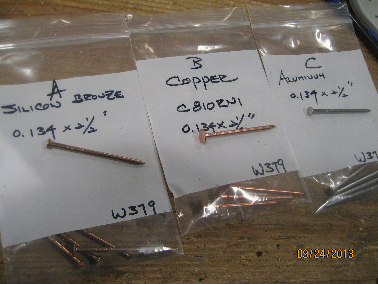
Simpson Strong-Tie sells a wide range of stainless steel nails made from several different alloys of Type 300 series stainless steel. In addition, Simpson Strong-Tie makes and sells nails made from copper, silicon bronze, and aluminum. The building codes (IBC® and IRC®) refer to stainless steel, copper, and silicon bronze as alternate materials for corrosion resistant construction, and aluminum nails are used for various fastening situations.
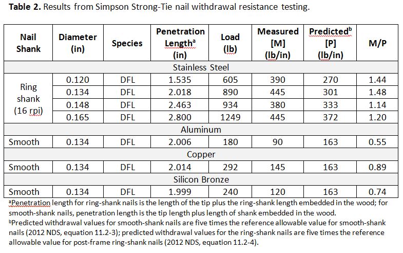
We ran some of the same withdrawal tests as Zelinka and Rammer, e.g., ASTM D1761, with nails made from stainless steel, copper, silicon bronze, and aluminum in Douglas Fir-Larch (DFL) visually-graded lumber that was conditioned to 12% moisture content. The nails, wood materials and results of our tests are shown in Table 2. The table includes predicted values based on the same equations as in Table 1, and we have shown a ratio of measured withdrawal resistance to predicted withdrawal resistance too.
For stainless steel nails, our results parallel the results of Zelinka and Rammer. The data from Table 2 show that the stainless steel ring-shank nails consistently perform at or above the post-frame ring-shank nail equation for all of the diameters. We went a step further than the literature and included withdrawal values for some smooth-shank nails of copper, silicon bronze, and aluminum. The measured-to-predicted ratios of Table 2 indicate that withdrawal resistance for the smooth-shank copper, silicon bronze, and aluminum are somewhat lower than expected based on the 2012 NDS smooth-shank withdrawal equation and are similar to the outcomes shown by Zelinka and Rammer for smooth-shank stainless steel nails.
Bending Yield Strength
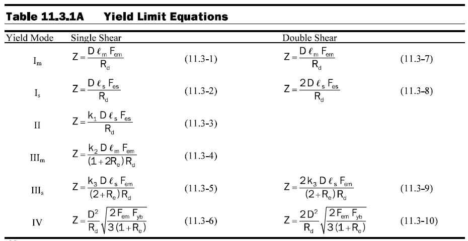
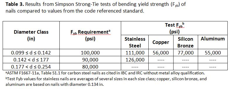
It is important to realize that connection design has to consider both withdrawal and shear. What properties of the fastener affect the lateral shear capacity of the connection? By inspection of the yield limit equations, 2012 NDS, Section 11.3, equation 11.3.1A, one of the critical properties is bending yield strength of the fastener. Do stainless steel, copper, silicon bronze, and aluminum have the expected bending yield strengths to use the yield limit functions without further modification? Simpson Strong-Tie did some bending yield tests on stainless steel, copper, silicon bronze, and aluminum by following ASTM F1575. The bending yield results are shown in Table 3.
The bending yield tests with our stainless steel nails are for Types 304/305, and the results for Type 316 will be similar. We categorized the results by diameter class just as in ASTM F1667, which is the reference standard for nails in the IBC section 2303.6, IRC R602.3, and 2012 NDS. Based on the bending yield test results, we can be confident that bending yield strength of stainless steel nails in all diameter classes meets the expectations of the standard for carbon steel nails and the code values, which are not qualified by alloy. However, the bending yield strengths for copper, silicon bronze, and aluminum are well below the codified values.
Effect of Withdrawal Resistance on Lateral Shear Resistance of Nail-Fastened Connectors
Will the withdrawal resistance also affect the shear performance of connections made with smooth-shank and ring-shank stainless steel nails? The yield limit equations for metal dowels that are published in 2012 NDS, section 11.3 assume that the dowel is smooth and headless and that no axial load is present. As a result, the 2012 NDS yield limit equations do not include a term for withdrawal resistance, but the yield limit equations in the design standards of some other countries do include a term for withdrawal in some of the yield modes. Where withdrawal is included in lateral resistance, the withdrawal component of lateral resistance is referred to as a “rope effect.”
In as much as the withdrawal resistance is not included in the 2012 NDS yield limit equations, the allowable design values may not be affected by the “rope effect,” and some yield modes certainly will not be affected by a reduction in withdrawal resistance.
However, we can anticipate that withdrawal resistance has some effect on the real ultimate connection shear strength for yield modes where dowel bending is expected to occur, such as Modes III and IV. This was a concern to us with respect to load-rated stainless steel connector products. We did some testing with stainless steel connectors fastened with stainless steel ring-shank nails. The testing confirmed that when the stainless steel connectors are installed with Simpson Strong-Tie stainless steel ring-shank nails, the load capacities for the stainless steel connectors are the same as the matching carbon steel connectors installed with carbon steel nails.
For this reason, Simpson Strong-Tie recommends that stainless steel connectors are fastened using Simpson Strong-Tie stainless steel ring-shank nails. See the Simpson Strong-Tie engineering letter L-F-SSNAILS13 for additional information.
Summary
Recent publication of stainless steel nail tests showed that withdrawal resistance of smooth-shank stainless steel nails has an eroded factor of safety when using the 2012 NDS withdrawal equation to calculate allowable withdrawal resistance. It appears that to protect the factor of safety for nail withdrawal resistance, the allowable nail withdrawal resistance for smooth-shank stainless steel nails should be adjusted by multiplying the calculated allowable withdrawal resistance by a factor of about 0.70. On the other hand, the withdrawal resistance of ring-shank stainless steel nails that are geometrically similar to post-frame ring-shank nails appears to follow the 2012 NDS withdrawal equation for post-frame ring-shank nails. We can infer from this result that the ring-shank nail performance is independent of the wood-metal coefficient of friction.
The withdrawal resistance of nails made from other metal alloys needs further study. The evidence presented here shows that smooth-shank nails made from copper, silicon bronze, and aluminum have withdrawal values that lag the 2012 NDS withdrawal function in a manner similar to stainless steel smooth-shank nails. However, based on our experience with stainless steel, we can expect ring-shank nails made from these other alloys to perform like carbon steel ring-shank nails and follow the post-frame ring-shank withdrawal equation in 2012 NDS.
The bending yield strength of stainless steel nails was shown to meet the requirements of the ASTM standard and the requirements of the building codes. This means that any loss in ultimate lateral shear capacity of connections made with smooth-shank stainless steel nails is a function of the diminished withdrawal resistance not a bending yield strength that is lower than expected.
One final note about the 2012 NDS, Table 11.2C. The withdrawal resistance values for “threaded” nails in this table are historic values and are not based on the new post-frame ring-shank nail equation.
– Bob
What are your thoughts? Visit the blog and leave a comment!