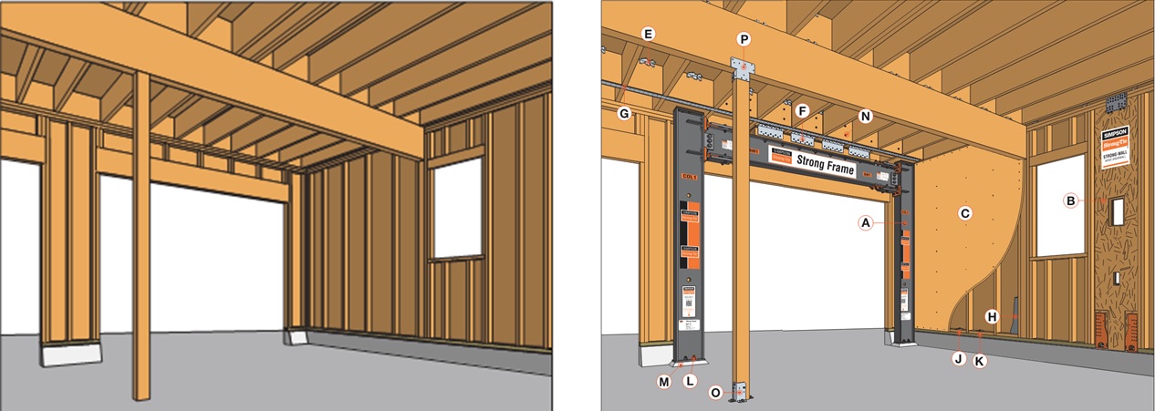
In a Structural Engineering Blog post I wrote last October, “Soft-Story Retrofits Using the New Simpson Strong-Tie Retrofit Design Guide,” one item I barely touched on at the time was the benefit of using Simpson Strong-Tie® Strong Frame special moment frames to retrofit vulnerable soft-story wood-framed buildings commonly found on the West Coast. In this post, I will be diving into more detail on a few features that make the Strong Frame special moment frame truly special.
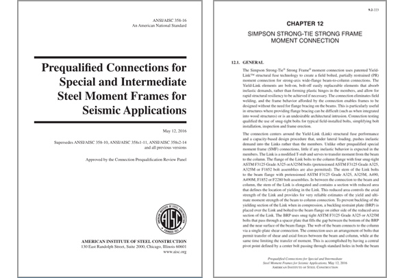
In the recent release of the ANSI/AISC 358-16 (AISC 358-16), the Simpson Strong-Tie Strong Frame moment connection has been included as a prequalified special moment frame (SMF) connection. Prequalified moment connections are structural-steel moment connection configurations and details that have been reviewed by the AISC Connection Prequalification Review Panel (CPRP) and incorporated into the AISC 358 standard. What’s unique about this newly prequalified connection is that it’s the first moment connection to be prequalified in AISC as a partially restrained (PR-Type) moment connection.
With this recent inclusion into AISC 358-16, we’ve also developed our newly released Strong Frame Design Guide to help designers understand the differences in design and detailing between the Strong Frame connection and traditional SMF connections. The following are just a few of the key differences discussed in this guide.
SMF Yielding Elements
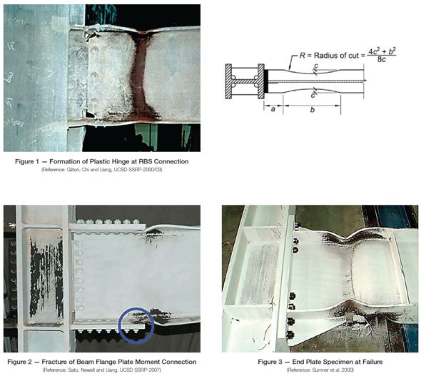
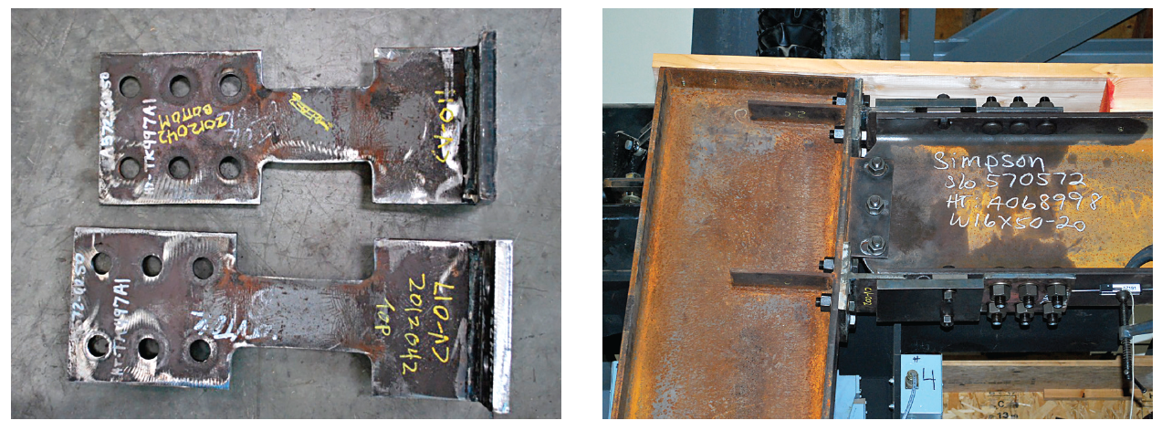
Traditional prequalified moment frames most often require a welded connection with either a weakened beam or a stiffened connection. SMF connections are designed so that the beam will yield as necessary under large displacements that may occur during a seismic event. The yielding of the beam section provides energy dissipation and is designed to ensure that the fully restrained beam-to-column connection isn’t compromised. The current design philosophy is the product of extensive testing of SMF connections based on studying the effects of the 1994 Northridge and 1989 Loma Prieta earthquakes in California. Figures 1, 2 and 3 below depict test specimens that demonstrate yielding at the designated areas of the beam.
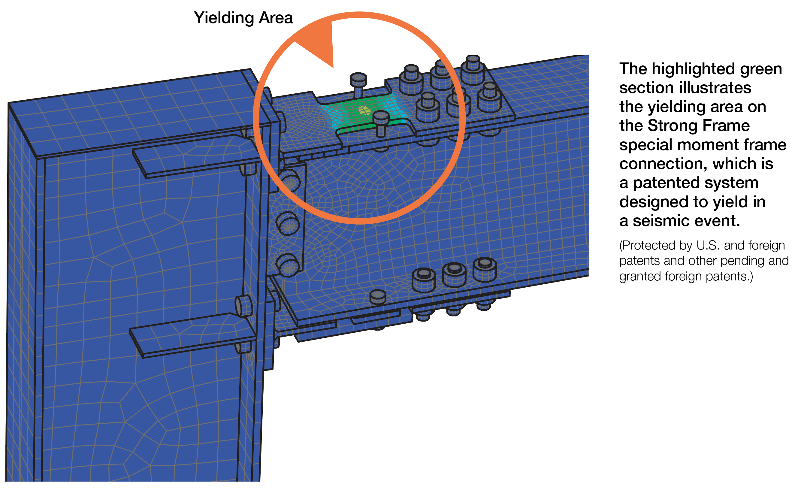
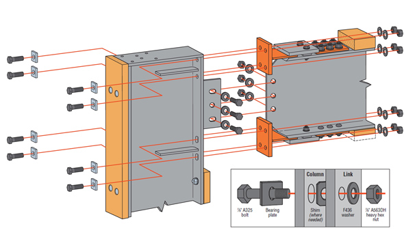
The Strong Frame SMF has taken a different approach to the traditional connections by utilizing a Yield-Link® structural fuse designed to provide the energy dissipation for the beam-to-column moment connection. This is a modified T-Stub that has a reduced section in the stem. The yielding during a seismic event has been moved from the beams to the Yield-Link structural fuse. The fuse can be replaced after a major event, very much like an electrical fuse when overloaded. A traditional moment frame may require a much more invasive structural repair.
Beam Lateral Bracing
The traditional types of prequalified connections, as along with other proprietary connections included in AISC 358, all require the beam to yield so as to dissipate energy as discussed above. These types of connections require that the beam be braced to resist the lateral torsional buckling per code. However, it is difficult to meet the bracing requirements in the case of a steel SMF in a wood structure.
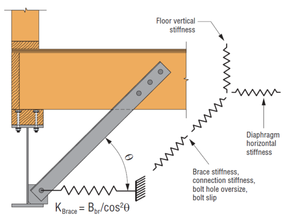
With the Strong Frame SMF connection, the energy dissipation is moved from the beams to the Yield-Link structural fuses, with the connection following a capacity-based design approach. This allows the connection to remain elastic under factored load combinations. With the yielding confined to the structural fuses, inelastic deformation is not expected from the members and lateral beam buckling braces are not required. The beam can be designed to span the entire length without beam bracing. See also this blog post.
Column-Beam Relationship Requirements
Traditional SMF follow a strong column – weak beam requirement to ensure plastic hinging occurs in the beams and not the columns. If the energy dissipation takes place within such hinging in the beams, the column members will remain elastic so as to provide stability and strength for the above stories. If plastic hinges occur in the columns, there is a potential for the formation of a weak-story mechanism.

The Strong Frame special moment frame is unlike the traditional SMF, where the plastic hinges are formed by the buckling of the beam flange and web. In the Strong Frame SMF, the stretching and shortening of the links at the top and bottom of the Strong Frame beams are the yielding mechanisms. So instead of a strong column – weak beam check, the Strong Frame design procedure checks for a strong column – weak link condition where the ratio of the column moments to the moment created by the Yield-Link® couple is required to be greater than or equal to 1.0.
Installation
Traditional moment frame connections typically require welding in the field. Where bolted SMF connections are used, pretensioned bolts are necessary. Both welding and pretensioned bolts require third-party special inspection.
The Strong Frame SMF has been designed and tested as a 100% field-bolted connection. Unlike other bolted options, the Strong Frame’s field-bolted connections only need to be made snug tight. No onsite bolt pretensioning or special inspections are required with this system. This allows the beams and columns to be maneuvered into place, erected and installed in a fraction of the time needed for the welding, lateral-beam-bracing installation and additional inspections or repairs that traditional moment frames typically require.
Design
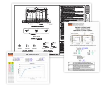
One last item I’d like to discuss is the design service that Simpson Strong-Tie provides for the Strong Frame special moment frame. Whether you design moment frames only once in a while or on a regular basis, the Strong Frame design team will provide you with No-Equal design support at no additional cost. Designers receive a complete package that includes drawings and calculations, which are submittal-ready. This ensures that you’ll have a frame connection design meeting the latest codes and design requirements. Contact strongframe@strongtie.com for more information or to request design support.
To learn more about the special benefits and uses of Strong Frame moment frames, check out the following links: