New LSSJ Hanger Strengthens Jack Rafter Connections

When our company is considering a new or improved product, we like to start out by talking to our customers first. That’s what we did recently with a connector improvement project for attaching jack rafter hangers in roof framing – and we got lots of feedback!

We heard from installers that they really wanted a hanger that could be easily adjusted in the field for different slopes and skews. We were asked whether we could design a hanger that could be installed after the rafters were already tacked into place to support construction sequencing and retrofit applications. Also, having a hanger that could be installed from one side was a popular time-saving request.

Our Engineering innovation team took all this feedback and closely evaluated our current selection of hangers. After much consideration, the team decided that rather than adapt one of our existing hangers, they would try to  come up with an all-new design that would satisfy our customers’ most pressing needs.

After months of designing and testing prototypes in the lab and in field trials, the answer was yes. The result is our new LSSJ field-adjustable jack hanger. It’s an innovative field-slopeable and field-skewable hanger that features a versatile hinged seat. This new design allows it to be adjusted to typical rafter slopes, with a max slope of 12:12 up or down.

What is a jack hanger and why does it provide a better connection than nails alone? 

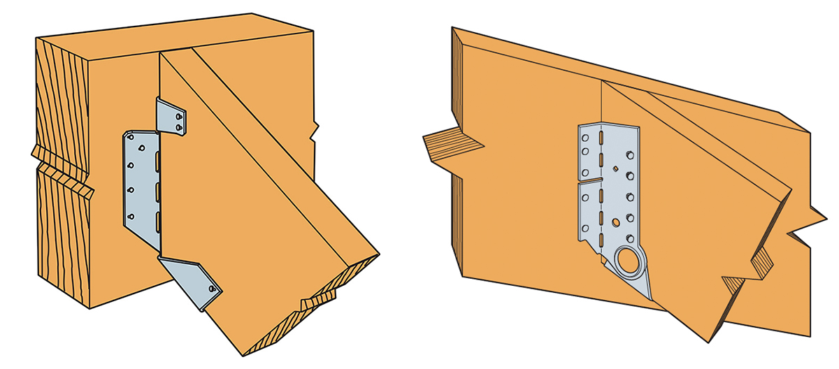
There are two basic types of wood roof construction: framed roof construction (stick framing) as shown above, and truss assembly. The main difference is that stick assembly takes place onsite, while trusses are prefabricated and ready to place. In the United States, the number of truss-built roofs versus stick-frame roofs is about two to one. The LSSJ jack hanger is used for stick-frame construction and provides a connection between the jack rafter to either the hip rafter or the valley rafter as shown below.

The LSSU hanger connects the jack rafter to the hip rafter
The LSSJ hanger connects the jack rafter to the hip rafter

Connecting a 2X jack rafter to a hip is hardly new. The hardest thing is making a good compound miter cut – something an experienced framer can figure out (and most engineers marvel at). In many parts of the country, these are simply face-nailed into place.  Often there isn’t a lot of engineering that goes into that connection.  However, a closer look raises a couple of questions.

Random Nail Placement

Where exactly are those nails going? When there’s no seat support for the rafter, the allowable shear is reduced per the NDS depending on where the lowest nail on the rafter is. This is based on the split that develops at the lowest fastener. The LSSJ provides a partial seat which not only meets the bearing requirement of section R802.6 of the IRC but also delays the type of splitting found in a nailed-only connection.

Consistent Nail Placement

The LSSJ conforms to the bottom of the jack rafter slope and ensures consistent nail placement on both the rafter and the hip.  Consistent nail placement promotes consistent performance based on testing (or as consistent as wood gets)!  The highest nail on the hip is located near the neutral axis if the hip is one size deeper than the rafter.  This assures that not all the load is focused at the bottom of the hip.

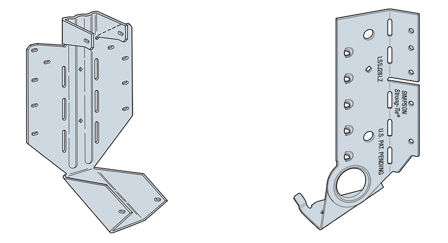
A Closer Look at the LSSJ Jack Hanger

Some of our customers may be familiar with our current product, the LSSU, which is used for the same connection. Here’s a closer look at the improvements that the LSSJ offers.

LSSU and LSSJ
LSSU and LSSJ
lssu-lssj-installation
LSSU and LSSJ Installation
lssu-lssj-Skewing
LSSU and LSSJ Skewing

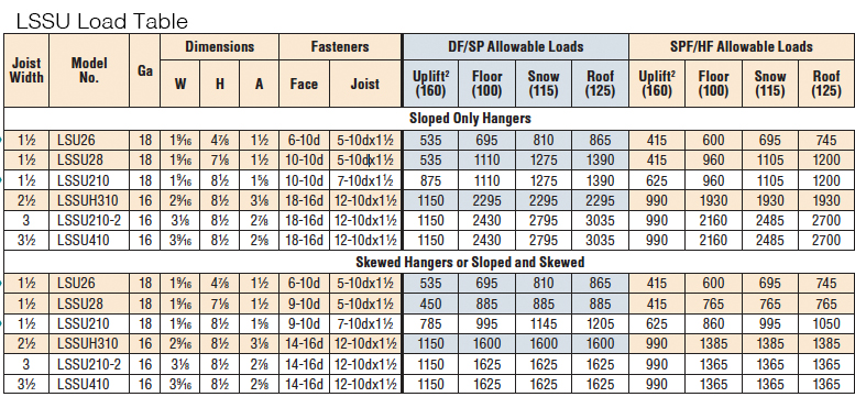
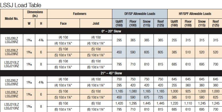
You can see the differences and improvements just by looking at these hangers, installations and load tables. Here’s a different way of showing the advances and benefits of the LSSJ:

LSSJ Improvements
LSSJ Improvements

One of the greatest improvements is the fact that there are fewer nails to install in the LSSJ, and the loads are very similar if not better.

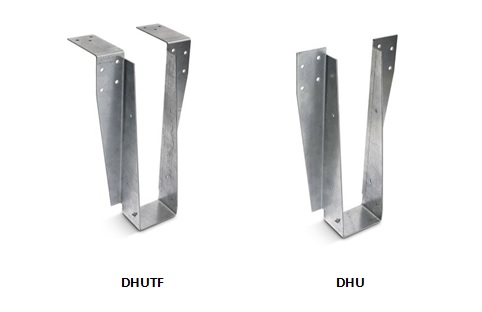
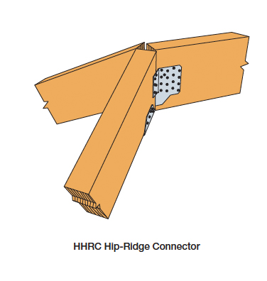
In addition to the LSSJ, Simpson Strong-Tie offers a full line of connectors for wood-framed sloped roofs, including:


We look forward to hearing from you about our newest innovation. For more information about the LSSJ hanger, please see strongtie.com.

Firewalls for Wood Construction

What is a firewall?

A firewall is a term that is used in the construction industry to describe a fire-resistive-rated wall or fire-stop system, which is an element in a building that separates adjacent spaces to prevent the spread of fire and smoke within a building or between separate buildings. A firewall is actually one of three different types of walls that can be used to prevent the spread of fire and smoke.

 Types of fire-resistive-rated walls: 

 The three types of fire-resistive-rated walls are firewalls, fire barriers and fire partitions. They are listed in order from the most stringent requirements to the least. A firewall is a fire-resistive-rated wall having protected openings, which restricts the spread of fire and extends continuously from the foundation to or through the roof with sufficient structural stability under fire conditions to allow collapse of construction on either side without collapse of the wall. A fire barrier is a fire-resistive-rated wall assembly of materials designed to restrict the spread of fire which continuity is maintained.  A fire partition is a vertical assembly of materials designed to restrict the spread of fire in which openings are protected.  Each type has varying requirements and the table below displays some of the differences between them.

fire-resistive-rated-wallsWhat are some of the typical uses of each type of fire-resistive wall? 

As the requirements for each type of wall vary, so do the uses. Typical uses of each are as follows:

  • Firewalls – party walls, exterior walls, interior bearing walls
  • Fire barriers – shaft enclosures, exit passageways, atriums, occupancy separations
  • Fire partitions – corridor walls, tenant space walls, sleeping units within the same building

How do you determine whether your wood building design needs a firewall?

The 2012 International Building Code (the IBC, or “the Code” in what follows), which is adopted by most building departments in the United States, is the resource we are using in this discussion. (As a side note, it’s possible your city or county has supplemental requirements, and it is best to contact your local building department for this information up front.)

To determine your fire-resistive wall requirements, review these chapters in the 2012 IBC:

  • Chapter 3, Identify Occupancy Group – typically Section 310 (“Residential Group”) for wood construction
  • Chapter 5, Select Construction Type – Section 504, Table 503
  • Chapter 6, Determine Fire-Resistive Rating Requirements – Table 601, typically Type III wood-constructed buildings require a two-hour fire separation for the exterior bearing walls

What are typical fire-resistive wall designs? 

 Information for one-hour, two-hour designs, etc. can be found in tables 721.1(2) and 721.1(3) of the Code provide information to obtain designs that meet the rating requirements (in hours) for your building, including the walls and floor/roof systems. The GA-600 is another reference that the Code allows if the design is not proprietary.

How do I know whether the structural attachments I specify for the wall and roof assemblies meet the Code requirement?

Once the wall or floor/roof assembly design is selected, the Designer must ensure that the components of the wall do not reduce the fire rating. The Code requires that products which pierce the membrane of the assemblies at a hollow location undergo a fire test to ensure they meet the requirements of the design. ASTM E814 and ASTM E119 are the standards governing the fire tests for materials and components of the fire-resistive wall. There are several criteria that the component in the assembly must meet: a flame-through criterion, a change-in-temperature criterion and a hose-stream test.

Simpson Strong-Tie has created the DHU hanger for use with typical two-hour fire-resistive walls for wood construction.The DHU hanger has passed the ASTM E814 testing and can be used on a fire-resistive wall of 2×4 or 2×6 constructions and up to two 5/8″ layers of gypsum board. The DHU and DHUTF have both an F (Fire) and a T (Temperature) rating.

dhutf-dhu-hangersThe DHU/DHUTF hanger has two options, a face-mount version (DHU) and a top-flange version (DHUTF).  The hanger doesn’t require any cuts or openings in the drywall, which ensures reliable performance; no special inspection is required.  To install the hanger, gypsum board must first be installed in a double or single layer, at least as deep as the hanger.  For installation, apply a two-layer strip of Type X drywall along the top of the wall, making the base layer a wider strip (bottom edge is 12″ or more below the face layer, depending on jurisdiction).  Then install ¼” x 3½” Simpson Strong-Tie Strong-Drive® SDS screws through the hanger and into top plates of the wall.  Since the hanger is more eccentric than typical, the top plates of the wall must be restrained from rotation. The SSP clip can be used for restraint, but the design may not require it if there is a sufficient amount of resistance already in place, such as sheathing, a bearing wall above, or a party wall as determined by the designer.  See the photos and installation illustration below for guidance or visit our website for further information.

typical-installation-over-2-layers-drywall