Introducing the Building Strong Blog

Building Strong Blog

This week we want to let you know about a new resource, the Building Strong blog. It’s very different from the SE Blog in that it ranges beyond the topics important to structural engineers to cover issues and various perspectives that help construction professionals of all disciplines design and build safer, stronger structures as efficiently as possible. We developed the new industry blog to highlight issues and topics that are of special interest to construction and building professionals. Through semi-monthly articles, the blog will cover topics ranging from rising labor costs to innovative technologies and the changing landscape of the building industry.

The Building Strong blog will cover topics on:

  • Safety, codes, and compliance
  • Residential and commercial construction
  • Decks and outdoor living
  • Building resilience
  • Emerging trends and industry insights
  • Collaborations and giving
  • Pro tips

We’re excited to offer the Building Strong blog. If you enjoy the SE Blog, this new content will give you a fresh take on timely topics affecting our industry. Check it out today!

The Cold-Formed Steel Construction Catalog is HOT off the press!

The SE Blog is taking some time off for the 4th of July holiday this week. However, we’ve just released the 2017 edition of our Connectors for Cold-Formed Steel Construction catalog – order a hard copy to be mailed to your office or download a PDF copy and start using it today!

Connectors For Cold-Formed Steel Construction

The C-CF-2017 is a 308-page catalog including specifications, load tables and installation illustrations for our cold-formed steel connectors and clips, helping you easily specify and install in commercial curtain-wall, mid-rise and residential construction.


Great ShakeOut Earthquake Drill 2016

The Great ShakeOut Earthquake Drill is an annual opportunity for people in homes, schools and organizations to practice what to do during earthquakes and improve their preparedness. In a post I wrote last October about the Great ShakeOut, I reminisced about the first earthquake I had to stop, drop and cover for – the Livermore earthquake in January, 1980. This year got me thinking about how our evacuation drills work.

At Simpson Strong-Tie, we use the annual Great ShakeOut drill to practice our building evacuation procedures. Evacuation drills are simple in concept – alarms go off and you exit the building. We have volunteer safety wardens in different departments who confirm that everyone actually leaves their offices. There are always a few people who want to stay inside and finish up a blog post. Once the building is empty and we have all met up in the designated meeting area, we do a roll call and wait for the all-clear to get back to work.

Several years ago the alarms went off. While waiting for the drill to end, we were concerned to see fire fighters arrive and rush into the building. Realizing this was not a drill, there were some tense moments of waiting. The fire chief and our president eventually walked out of the building and our president was yelling for one of our engineers. Turns out the engineer (who shall remain nameless) was cooking a chicken for lunch. Yes, a whole chicken. The chicken didn’t make it – I’m not sure what the guilty engineer had for lunch afterwards. At least we received extra evacuation practice that year. We aren’t allowed to cook whole chickens in the kitchen anymore.

Simpson Strong-Tie is helping increase awareness about earthquake safety and encouraging our customers to participate in the Great ShakeOut, which takes place next Thursday on October 20. It’s the largest earthquake drill in the world. More than 43 million people around the world have already registered on the site.

On October 20, from noon to 2:00 p.m. (PST), earthquake preparedness experts from the Washington Emergency Management Division and FEMA will join scientists with the Washington Department of Natural Resources and the Pacific Northwest Seismic Network for a Reddit Ask Me Anything – an online Q&A. Our very own Emory Montague will be answering questions. The public is invited to ask questions here. (Just remember that this thread opens the day before the event and not sooner.)

Emory Montague from Simpson Strong-Tie
Emory, ready to answer some seismic-related questions.

We’re also providing resources on how to retrofit homes and buildings, and have information for engineers here and for homeowners here.

Earthquake risk is not just a California issue. According to the USGS, structures in 42 of 50 states are at risk for seismic damage. As many of you know, we have done a considerable amount of earthquake research, and are committed to helping our customers build safer, stronger homes and buildings. We continue to conduct extensive testing at our state-of-the-art Tye Gilb lab in Stockton, California. We have also worked with the City of San Francisco to offer education and retrofit solutions to address their mandatory soft-story building retrofit ordinance and have created a section on our website to give building owners and engineers information to help them meet the requirements of the ordinance.

Last year, Tim Kaucher, our Southwestern regional Engineering Manager, wrote about the City of Los Angeles’s Seismic Safety Plan in this post. Since that time, the City of Los Angeles has put that plan into action by adopting mandatory retrofit ordinances for both soft-story buildings and non-ductile concrete buildings. Fortunately, California has not had a damaging earthquake for some time now. As a structural engineer, I find it encouraging to see government policy makers resist complacency and enact laws to promote public safety.

Participating in the Great ShakeOut Earthquake Drill is a small thing we can all do to make ourselves more prepared for an earthquake. If your office hasn’t signed up for the Great ShakeOut Earthquake Drill, we encourage you to visit shakeout.org and do so now.

How to Select a Connector Series – Holdowns

Keith Cullum started off our “How to Select a Connector” series with Hurricane Ties. This week we will discuss how to select holdowns and tension ties, which are key components in a continuous load path. They are used to resist uplift due to shearwall overturning or wind uplift forces in light-frame construction. In panelized roof construction, holdowns are used to anchor concrete or masonry walls to the roof framing.

shearwall-segment

Holdowns can be separated in two basic categories – post-installed and cast-in-place. Cast-in-place holdowns like the STHD holdowns or PA purlin anchors are straps that are installed at the time of concrete placement. They are attached with nails to wood framing or with screws to CFS framing. After the concrete has been placed, post-installed holdowns are attached to anchor bolts at the time of wall framing. The attachment to wood framing depends on the type of holdowns selected, with different models using nails, Simpson Strong-Tie® Strong-Drive® SDS Heavy-Duty Connector screws or bolts.

A third type of overturning restraint is our anchor tiedown system (ATS), which is common in multistory construction with large uplift forces. I discussed the system in this blog post.

methods-of-overturning-restraintGiven the variety of different holdown types, a common question is, how do you choose one?

For prescriptive designs, such as the IRC portal frame method, the IRC or IBC may require a cast-in-place strap-style holdown. Randy Shackelford did a great write-up on the PFH method in this post.

For engineered designs, a review of the design loads may eliminate some options and help narrow down the selection.

Holdown TypeMaximum Load (lb.)
Cast-in-Place5,300
Nailed5,090
SDS Screws14,445
Bolted19,070

sthd-installation

htt-installation

hdb-installation

hdu-installation

I like flipping through catalog pages, but our Holdown Selector App is another great tool for selecting a holdown to meet your demand loads. Select cast-in-place or post-installed, enter your demand load and wood species, and the application will list the holdown solutions that work for your application.

holdown-selector-app

The application lists screwed, nailed and bolted solutions that meet the demand load in order of lowest installed cost, allowing the user to select the least expensive option.

Adjustability should be considered when choosing between a cast-in-place and a post-installed holdown. Embedded strap holdowns are economical uplift solutions, but they must be located accurately to align with the wood framing. If the anchor bolt is located incorrectly for a post-installed holdown, raising the holdown up the post can solve many problems. And anchors can be epoxied in place for missing anchor bolts.

offset-holdown-raised-off-sillWe are often asked if you can double the load if you install holdowns on both sides of the post or beam. The answer is yes, and this is addressed in our holdown general notes.

notes-on-doubling-loads

Nailed or screwed holdowns need to be installed such that the fasteners do not interfere with each other. Bolted holdowns do not need to be offset for double-sided applications. Regardless of fastener type, the capacity of the anchorage and the post or beam must be evaluated for the design load.

double-sided-bolted-purlin-cross-tie

double-sided-hdu-offset-installation

Once you have selected a holdown for your design, it is critical to select the correct anchor for the demand loads. Luckily, I wrote a blog about Holdown Anchorage Solutions last year. What connector would you like to see covered next in our series? Let us know in the comments below.

Five Simpson Strong-Tie employees had the opportunity to participate in a week-long Habitat for Humanity build in the small town of Amarante, Portugal, in late April. The company decided to allocate the funds for the CWP to Habitat’s Global Village program, allowing these employees to help renovate and remodel the older home of a widowed mother (Doña Margarida Ribiero) and daughter (Sonia) living in the Portuguese countryside.

Building with Habitat for Humanity in Portugal

Five Simpson Strong-Tie employees had the opportunity to participate in a week-long Habitat for Humanity build in the small town of Amarante, Portugal, in late April. The group was originally scheduled to work on a Habitat project in Nepal late last year as part of Habitat’s Jimmy and Rosalynn Carter Work Project (CWP), but following the signing of a new constitution and civil unrest in the country, the project was canceled.Continue Reading

Multi-Ply Beam Load Transfer

Larger beams are often built up out of smaller 2x or 1¾” members. This can be done for several different reasons: for the convenience of handling smaller members on the jobsite, or because solid 4x, 6x or glulam material is not readily available, or for reasons of cost. Engineered wood such as laminated veneer lumber (LVL) is often used for its high load capacity and multiple 1¾” plies are built up to get the required capacity for the application.

8-Ply LVL Beam in HHGU14 Test

When a built-up beam is loaded concentrically as in the test setup shown, fastening the members is not critical since that giant steel plate will load each ply of the beam. In the field, built-up beams or girders commonly support joists or beams framing into their side. The built-up members must be connected to transfer load from the loaded ply into the other plies.

SDW - Uniform Allowable Loads
Allowable Uniform Loads and Spacing Requirements

SDW - Assembly Types and Spacing Requirements

Page 303 of our Fastening Systems catalog, C-F-14 provides allowable uniform load tables for side-loaded multi-ply assemblies using LVL, PSL or LSL material. The calculation for the allowable load applied to the outside ply of a multi-ply beam is:

Screen Shot 2016-04-28 at 2.07.29 PM

While uniform loads are very common, Designers often request additional information to design multi-ply beam connections to transfer concentrated loads. Simpson Strong-Tie has created a new engineering letter, L-F-SDWMLTPLY16, which complements the information in the Fastening Systems catalog by providing allowable loads in a single fastener format. Designers can use the information to calculate the number of fasteners required for a given point load.

Simpson Strong-Tie® Strong-Drive® SDW EWP-Ply Screw – Allowable Loads for Side-Loaded Multi-Ply Assemblies per Screw

In order to ensure load transfer, the SDW screws need to be located relatively close to the connection. At first glance, it may appear challenging to fit enough fasteners while meeting the non-staggered row-spacing requirements. However, we have found that most loads can be managed by taking advantage of the ⅝” stagger allowance.

SDW – Maximum Fastener Spacing from Point Load

If you are curious what happened in that HHGU14 test, the screws pulled out of the header with a load slightly exceeding 101,000 pounds. Failure photo 2 shows a close-up of the pullout failure. The tested load was very close to the maximum calculated capacity for the SDS screws in the connector, so it was a great test result. What are your thoughts? Let us know in the comments below.

HHGU14 Test Failure 1 HHGU14 Test Failure 2

Fine Homebuilding Video Series: How to Build a Deck

We’re partnering with folks at Fine Homebuilding on a video series on how to build a deck that is code compliant and that highlights the critical connections of a deck. This series is called Ultimate Deck Build 2016. The video series comprises five videos that walk professionals through the recent code changes for the key connections of a deck.

The series features David Finkenbinder, P.E., a branch engineer for Simpson Strong-Tie who is passionate about deck codes and safety. He offers information on load resistance and the hardware that professionals can use at the crucial connections to make a deck code compliant. “This was a great opportunity to collaborate with the team at Fine Homebuilding, to communicate the connections on a typical residential deck and the role that they serve to develop a strong deck structure,” said David. “These same connections would also likely be common in similar details created by an Engineer, when designing a deck per the International Building Code (IBC).”

Screen Shot 2016-03-30 at 3.49.17 PM

The videos are being released every Wednesday during the month of March and feature the following deck connections:

  • Ledger Connection: This is the primary connection between a deck and a house. David tells the Fine Homebuilding team about various code- compliant options for attaching a deck ledger to a home.
  • Beam and Support Posts: David explains how connectors at this critical point can prevent uplift and resist lateral and downward forces. He also discusses footing sizes and post-installation anchor solutions.
  • Joists: This video reviews proper joist hanger installation and the benefits of installing hurricane ties between the joists and the beams. David goes into common joist hanger misinstallations, such as using the wrong fasteners or using a joist hanger at the end of a ledger.
  • Guardrail Posts: David reviews the different ways that you can attach a guardrail post so as to resist an outward horizontal load.
  • Stairs: David explains code-compliant options for attaching stringers to a deck frame.

Make sure to watch the series and let us know what you think. For more information, Fine Homebuilding has created an article titled “Critical Deck Connections.”

(Please note: this article is member-only/subscription content, so to read it you’ll need to either subscribe online or pick up the April/May issue of Fine Homebuilding.)

Screen Shot 2016-03-30 at 4.06.33 PM

Installation Errors – They Happen

A few years ago, we did a post on creative uses of our products. Most of the uses shown were artistic, or functional do-it-yourself projects, with one odd car spoiler modification. This week, I was reviewing some slides in a presentation that I give a few times a year regarding product installation errors. I call them misinstallations, but I’m not sure that’s a word. I thought I’d share a few of the more instructional ones. Most of the photos were curated by our northwestern region training manager, Olga Psomostithis – thanks Olga!

Double Shear Hangers

install1

Double shear hangers require joist fasteners that are long enough to penetrate through the hanger, through the joist and into the header. The joist nails help transfer load from the joist into the header, resulting in higher allowable loads.

install2.1

The installation shown has had the double shear tabs bent back, and nails installed straight into the joist. Since the joist nails do not penetrate the header, this would result in a reduced capacity.

Holdowns

I’m including the trailer hitch installation because it makes me laugh no matter how many times I see it.

install4

A very common question we get about holdowns is related to posts being offset too far from the anchor bolt (or is the anchor too far from the post?). In the installation shown below, the holdown is not flush with the post as the anchor bolt is offset about 1 inch. For small offsets up to about 1½”, a common solution is to raise the holdown off the sill plate and extend the anchor bolt with a coupler and bend it so there is a small (1:12) slope to it.

install5

The holdown test standard, ICC-ES AC155, which is discussed in this post, requires that holdowns are tested raised off the test bed, which you can see in the photo below. Holdowns may be raised up to 18” above the top of concrete without a reduction in load provided that the additional elongation of the anchor rod is accounted for.

install6

install7

I like this photo because the installer put on the nail stops to protect the pipes. It is good to remember that plumbing happens when laying out a structural system.

Oh boy, does it happen.

install9STHD Holdowns

install12

install16

The photo above is not a misinstallation, but something that can happen. Embedded strap-style holdowns are cost-effective solutions for shearwall overturning or wind uplift. It is permitted to bend the straps to horizontal and back to vertical one cycle. If spalls form, they should be evaluated for reduced loads. Any portion of the strap left exposed should be protected against corrosion.

Hanger Gaps

install13

Gaps can occur between trusses and supporting girders for a variety of reasons. For standard hanger tests, a 1/8″ gap is required between the joist and header per ASTM D7147. A resource for evaluating conditions with larger gaps is our technical bulletin Allowable Loads for Joist Hangers with Gaps. The technical bulletin has load data for a variety of hangers with gaps up to 3/8″, as well as recommended repairs for larger gaps. Our HTU product series comprises truss hangers specifically engineered to allow gaps up to ½”.

install14

install15

After going through a design project and carefully selecting the members and details of construction, it can be frustrating as an engineer to get that phone call from the general contractor or building inspector informing you that something is not right with the construction. Understanding some of the resources available to address installation errors can help solve these problems more quickly, and get you back to designing the next project.

Cold-Formed Steel Connectors

This blog has described how we load rate different products based on test standards, which are covered under various ICC-ES Acceptance Criteria, or ACs. The first was a post on wood connectors (AC13), then holdowns (AC155), threaded fasteners (AC233) and cast-in-place anchors for light-frame construction (AC398 and AC399). I realized today that I have never talked about how we test and load rate connectors for cold-formed steel.

AC261 Joist Test 1

But first, a confession – it has taken me many years to stop calling it “light-gauge steel.” When I started designing with cold-formed steel, I called it “light-gauge” because I had a binder of design information put together by the Light Gauge Steel Engineers Association. Advocates for CFS felt that “light-gauge” may make people think “weak” or “non-structural,” and that perception would limit the use of cold-formed steel in construction. So there was a deliberate effort to banish the word light-gauge and replace it with cold-formed steel, or CFS. I still slip every once in a while.

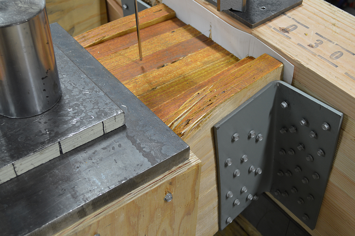
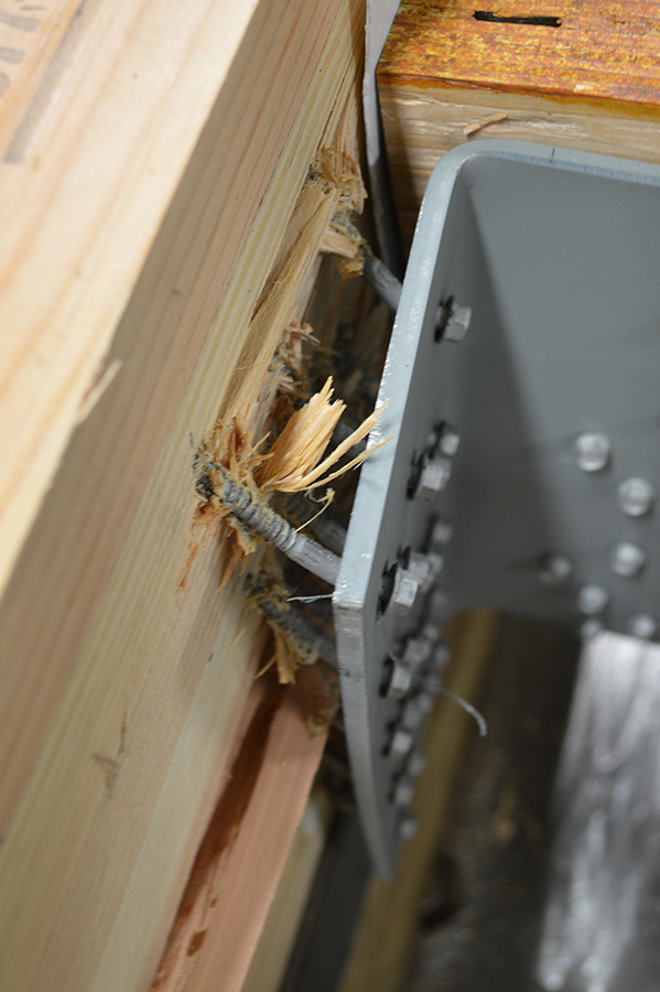
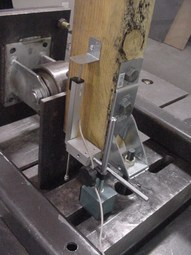
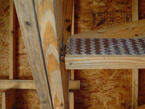
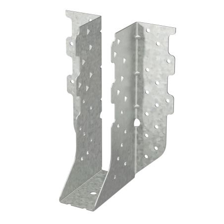
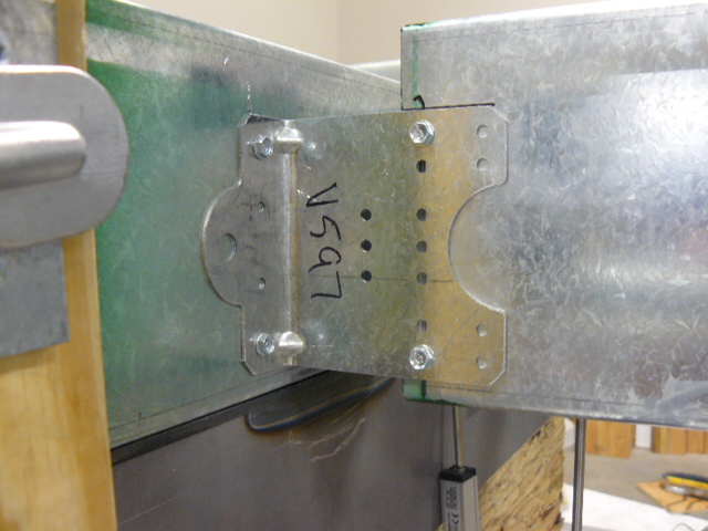
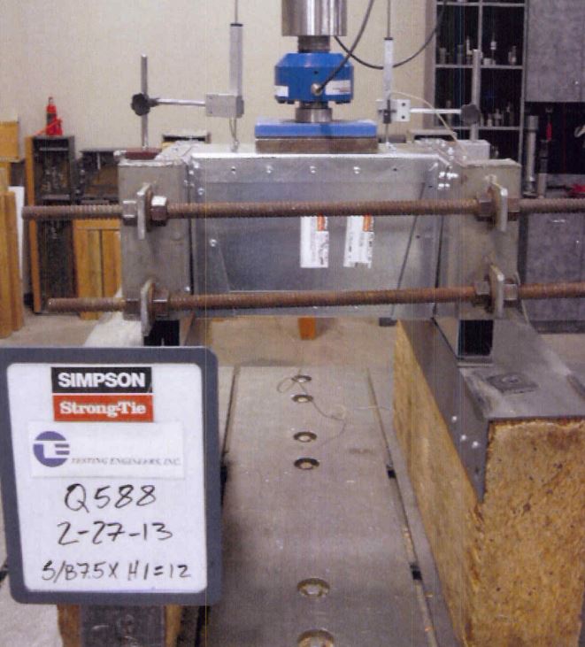
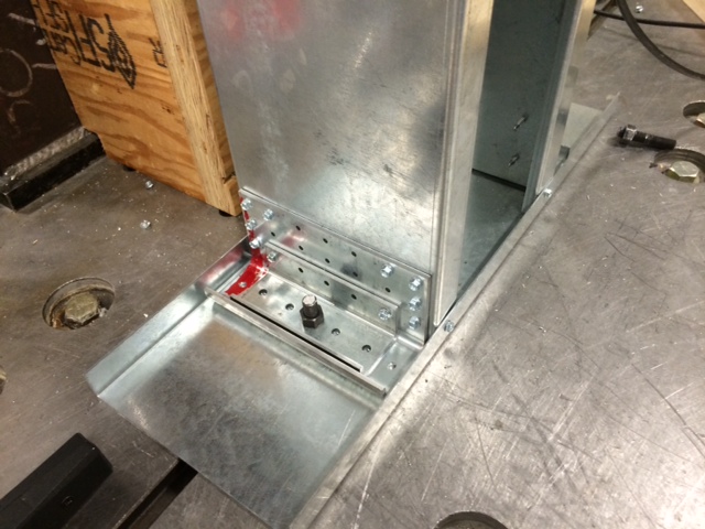
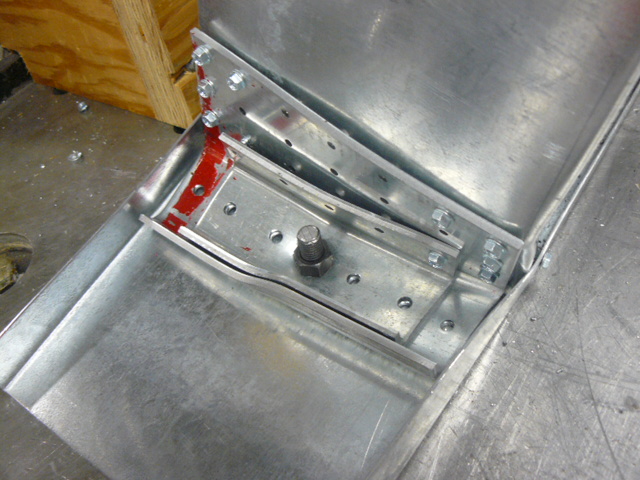
Connectors for light-gauge, ahem, I mean cold-formed steel members are covered under ICC-ES AC261 – Acceptance Criteria for Connectors Used with Cold-formed Steel Structural Members. The physical testing for cold-formed steel is similar to wood connectors. Build a setup representative of field conditions, apply load till failure and measure the load and deflection data. Both wood-to-wood and CFS connectors have a service limit state of 1/8” deflection.

Strength data for CFS connectors is analyzed much differently, however. Wood connectors generally use a safety factor of 3 on the lowest ultimate load (or average ultimate if six tests are run). We are often asked what the safety factor for CFS connectors is.

AISI S100 Safety Factor

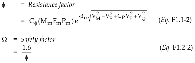
AISI S100 Chapter F details how to determine design strengths for tested CFS products. The design strength is the average test value, Rn, multiplied by an LRFD resistance factor, Φ, or divided by an ASD safety factor, Ω. Determining the resistance factor or corresponding safety factor is based on a statistical analysis dependent on several variables. This is similar in concept to how embedded concrete connectors tested to AC398 or AC399 are evaluated, which I discussed in this post.

AC261 Joist Test 2

I don’t want to get too deep into the Greek letters involved in the calculation. The factors that affect the allowable load calculation are type of member tested, variation in the test values, type of manufacturing, and number of samples tested. One factor that has a large impact on the calculation is the target reliability index, βo. In connector testing, this factor is 2.5 if the structural member (joist, stud, track, etc) fails and 3.5 if the connection fails. The net result is a higher safety factor for test values limited by the connection, and lower safety factors if the structural members governed the test load. Typical safety factors for CFS connectors are 1.8 to 2.0 where the failure mode is in the structural members and 2.2 to 2.9 for tests where the connection failed.

Strength Reduction Factor

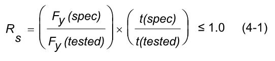
AC261 has a reduction factor, RS, which is used to adjust test values if your steel strength and/or steel thickness are over the specified minimum. CFS test setups often use different steel in the joist, header and the connector. Reductions are calculated based on the tested and specified strength and thickness for each member. The lowest reduction is used to adjust the test values.

RCKW Kneewall Setup

RCKW Kneewall Failure

One additional complexity in CFS testing is the multiple gauges of steel which must be evaluated. This requires more CFS test setups than a comparable wood connector would require. In the end, we have what we are really after. Design loads that specifiers can be confident in.

RCKW Load Table