The use of high-strength steels in anchors and fasteners is not unusual in the construction world. For example, high-strength threaded rods are often used to reduce the number of mild-steel rods that would be required to meet a design load for an adhesive anchor. High-strength steel is essential to the function of some fasteners, such as self-drilling and self-tapping screws.
However, for anchors and fasteners, there are limits to what can be accomplished by increasing steel strengths due to a phenomenon known as hydrogen embrittlement. Hydrogen embrittlement is well known by anchor and fastener manufacturers, but it is not widely known by structural engineers. The purpose of this blog post is to provide an overview of this important subject and some insight into one reason why steels used in construction anchors and fasteners have upper strength limits.
What is hydrogen embrittlement?
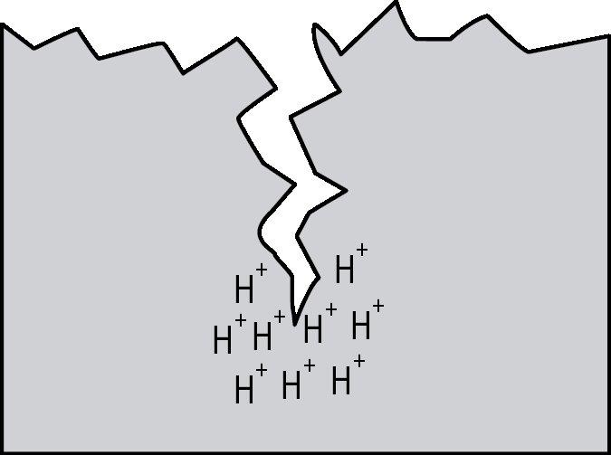
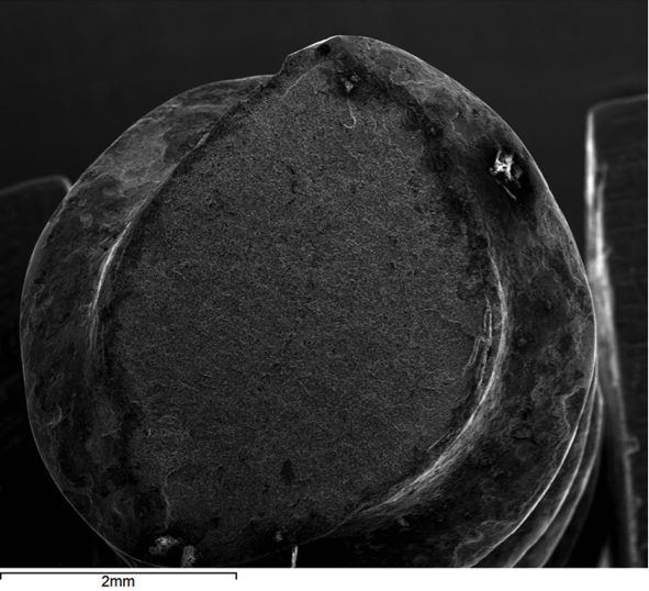
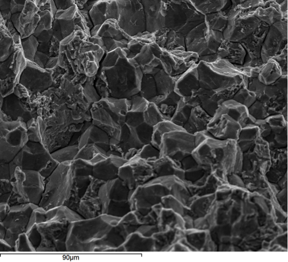
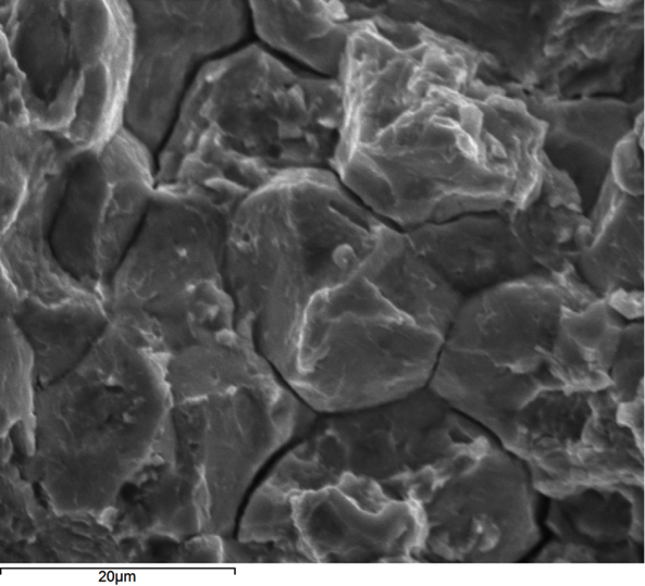
Hydrogen embrittlement is a significant permanent loss of strength that can occur in some steels when hydrogen atoms are present in the steel and stress is applied. Embrittlement occurs as hydrogen atoms migrate to the region of highest stress and cause microcracks. When a crack forms, the hydrogen then migrates to the tip of the crack (Figure 1) and causes continued crack growth until the effective fastener cross-section is so reduced that the remaining cross-section is overloaded and the fastener fails. Figures 2, 3 and 4 show a failure plane and coarse granular morphology and intergranular cracks (dark lines in Figures 3 and 4). These failures occur suddenly, without warning, after the fastener or rod has been loaded for a period of time.
All three of the aforementioned conditions must be present for hydrogen embrittlement to occur:
- A steel that is susceptible to hydrogen embrittlement
- Atomic hydrogen (H+ ions, not H2 gas)
- Stress, such as from tightening or applied loads
If an application involves these, then there is a possibility of hydrogen embrittlement and fastener failure. The possibility of and time to failure depend on the degree of each of these conditions. Therefore, the level of concern should depend on the degree to which the Designer expects all three of these conditions to be present in the application.
What steels are sensitive to hydrogen embrittlement?
A fastener’s susceptibility to hydrogen embrittlement increases with elevated tensile strength or hardness. It is generally accepted that good-quality fasteners with an actual (not specified) Rockwell C scale hardness of less than 38 (tensile strength of less than approximately 170,000 psi) are not ordinarily susceptible to hydrogen embrittlement. Fastener manufacturers often establish lower hardness limits as an extra margin of safety for variability that may occur in production.
When are hydrogen atoms (H+) present?
Hydrogen atoms can be introduced into a fastener from manufacturing or from the service environment.
Sources of hydrogen from manufacturing:
Hydrogen can be present in the steel-making process, but the amount present in good-quality steel is below the level that causes problems. The most common way that hydrogen is introduced during anchor and fastener manufacturing is from the cleaning and coating processes. These processes often utilize acids that produce hydrogen. Compounding this problem is that many popular coatings like zinc plating (ASTM B633) and hot-dip galvanizing (ASTM A153) create a barrier around the fastener that does not allow hydrogen to easily diffuse out of the fastener. Some coatings, like mechanical galvanizing (ASTM B695), do have sufficient porosity that hydrogen can diffuse through the coating at room temperature.
Manufacturers most commonly manage internal hydrogen sources by minimizing cleaning time and by baking plated fasteners after coating for a number of hours to help diffuse hydrogen through the coating and out of the fastener. In some cases, mechanical cleaning and alkaline cleaning are used to prevent hydrogen from being introduced.
In cases where internal hydrogen is not properly managed in the manufacturing process, failure usually occurs quickly, within 48 hours of fastener installation.
External sources of hydrogen:
Hydrogen can also be introduced from the service environment. Zinc coatings galvanically protect steel from corrosion in damp or wet service environments. However, this process results in an electric current being passed through the water (H2O) to produce hydrogen (H+) and hydroxide (OH–) ions as shown in Figure 5. Since this process requires corrosion to generate the hydrogen, failures from externally generated hydrogen usually take much longer to occur than when internal hydrogen is the cause. Steel failure from externally generated hydrogen can take anywhere from weeks to years.

How much stress is too much stress?
Fortunately, for products that require very high-strength steels, hydrogen embrittlement risk diminishes, even for sensitive steels, as applied loads are reduced. For such products there are a number of complex tests that fastener manufacturers utilize in development and quality control to verify that the risk of hydrogen embrittlement is controlled for the intended application at the rated loads.
Closing thoughts
As illustrated in the discussion above, hydrogen embrittlement can be a serious concern for high-strength anchors and fasteners. A Designer should exercise great care to guard against the sudden brittle steel failure that this phenomenon can produce. There are a number of good practices to follow in this regard:
- Do not utilize exotic high-strength steels with actual tensile strengths greater than 170,000 psi (Rockwell C-scale hardness of 38) without carefully considering hydrogen embrittlement risk. Note that actual tensile strength may be higher than specified tensile strengths.
- Ensure that quality sources of high-strength fasteners are specified. High-quality manufacturers have design and manufacturing practices in place to guard against hydrogen embrittlement.
- Use discretion in selecting very high-strength fasteners for corrosive applications since these conditions often produce hydrogen through the galvanic process.

