Simpson Strong-Tie Now Offering a Structural Engineering/Architecture/Construction Management Student Scholarship Program

We know it’s tough going to school and majoring in structural engineering or architecture. You probably weren’t aware of this, but I went to Brooklyn Technical High School and we were required to take mechanical drafting, electrical engineering and wood/metal shop before we selected majors at the end of our sophomore year. I actively avoided majoring in architecture and engineering because, while I was a whiz at the lathe in metal shop, I was much less talented in some of the other engineering subjects.

draft1
Mechnical drafting class in Brooklyn Technical High School. (Photo courtesy of Brooklyn Technical High School)

I sometimes wish I had been better at them, because getting a degree in structural engineering and architecture isn’t just cool (where else can you get college credit or money to break stuff?), it can help you improve the lives of others and even make them safer. Simpson Strong-Tie Company, Inc. established the structural engineering/architecture scholarship program to assist architecture and structural engineering students by supporting their education and encourage them to design and build safer structures in their local communities.

And it seems as though there are more and more students committed to those goals, too. Last year, Simpson Strong-Tie awarded 49 scholarships of $2,000. The year before, Simpson Strong-Tie awarded 38 scholarships of $1,000. This year, Simpson Strong-Tie is offering up to 67 scholarship awards of $2,000 for the 2016/2017 academic school year. Applicants must be enrolled as juniors or seniors in full-time undergraduate study (60 semester hours or equivalent) majoring in architecture, structural engineering or construction management at the following colleges or universities for the entire upcoming academic year:

  • Arizona State University
  • Boise State University
  • Brigham Young University
  • California State Polytechnic University, Pomona
  • California State Polytechnic University, San Luis Obispo
  • California State University, Fresno
  • California State University, Fullerton
  • California State University, Long Beach
  • California State University, Sacramento
  • Clemson University
  • Florida International University
  • Georgia Institute of Technology
  • Iowa State University
  • Louisiana State University
  • Milwaukee School of Engineering
  • NYU Polytechnic School of Engineering
  • North Carolina State University
  • Ohio State University, Columbus
  • Oklahoma State University
  • Oregon Institute of Technology
  • Oregon State University
  • Penn State University Park
  • Portland State University
  • Purdue University, West Lafayette
  • Southern California Institute of Architecture
  • Texas Tech University
  • University of Arizona
  • University of California, Berkeley
  • University of California, Davis
  • University of California, Irvine
  • University of California, Los Angeles
  • University of California, San Diego
  • University of Cincinnati
  • University of Florida
  • University of Idaho
  • University of Illinois at Urbana-Champaign
  • University of Miami
  • University of Michigan
  • University of Nevada, Las Vegas
  • University of North Texas
  • University of Southern California
  • University of Texas, Arlington
  • University of Texas, Austin
  • University of Washington
  • University of Wyoming
  • Virginia Polytechnic Institute and State University
  • Washington State University


The scholarship application will be available on the Simpson Strong-Tie website as of March 15, so if you know any students enrolled in a structural engineering, architecture or construction management major at the schools listed above, you should advise them about this wonderful opportunity. If you have any questions or comments, please let us know in the comments below.

Shrinkage Compensation Devices

Over the weekend, I had the pleasure of watching my daughter in her cheer competition. I was amazed at all the intricate detail they had to remember and practice. The entire team had to move in sync to create a routine filed with jumps, tumbles, flyers and kicks. This attention to detail reminded me of the new ratcheting take-up device (RTUD) that Simpson Strong-Tie has just developed to accommodate 5/8″ and ¾” diameter rods. The synchronized movement of the internal inserts allows the rod to move smoothly through the device as it ratchets. The new RTUDs are cost effective and allow unlimited movement to mitigate wood shrinkage in a multi-story wood- framed building. When designing such a building, the Designer needs to consider the effect of shrinkage and how to properly mitigate it.

Our SE blog post on Continuous Rod Restraint Systems for Multi-Story Wood Structures explained the importance of load path and  the effects of wood shrinkage. This week’s blog post will focus on the importance of mitigating the shrinkage that typically occurs in multi-story light-frame buildings.

Shrinkage is natural in a wood member. As moisture reaches its equilibrium in a built environment, the volume of a wood member decreases. The decrease in moisture causes a wood-framed building to shrink.

The IBC allows construction of light-framed buildings up to 5 and 6 stories in the United States and Canada respectively. Based on the type of floor framing system, the incremental shrinkage can be up to ¼” or more per floor. In a 5-story building, that can add up to 1-¼” or more and possibly double that when construction settlement is included.

rods1
Typical Example of gap forming between nut and plate when wood shrinkage at top level occurs without shrinkage device.

The Simpson Strong-Tie Wood Shrinkage Calculator is a perfect tool to determine the total shrinkage your building can experience.

Wood Shrinkage Calculator

In order to accommodate the shrinkage that occurs in a multi-story wood-framed building, Simpson Strong-Tie offers several shrinkage compensating devices. These devices have been tested per ICC-ES Acceptance Criteria 316 (AC316) and are listed under ICC-ES ESR-2320 (currently being updated for the new RTUD5, RTUD6, and ATUD9-3).

AC316 limits the rod elongation and device displacement to 0.2 inches between restraints in shearwalls. This deflection limit is to be used in calculating the total lateral drift of a light-framed wood shearwall.

rod3
3 Part Shearwall Drift Equation

The 0.2-inch allowable limit prescribed in AC316 is important to a shearwall’s structural ability to transfer the necessary lateral loads through the structure below to the foundation level. This limit assures that the structural integrity of the nails and sill plates used to transfer the lateral loads through the shearwalls is not compromised during a seismic or wind event. Testing has shown that sill plates can crack when excessive deformation is observed in a shearwalls. Nails have also been observed to pull out during testing.  Additional information on this can be found here.

rod4
Sill Plates Cracked due to excessive uplift at ends of shearwall.
rods5
Nails pull out due to excessive uplift at ends of shearwall.

In AC316, 3 types of devices are listed.

  • Compression-Controlled Shrinkage Compensating Device (CCSCD): This type of device is controlled by compression loading, where the rod passes uninterrupted through the device. Simpson Strong-Tie has several screw-type take-up devices, such as the Aluminum Take-Up Device (ATUD) and the Steel Take-Up Device (TUD), of this type.
rods6
ATUD (CCSCD)
  • Tension-Controlled Shrinkage Compensating Device (TCSCD): This type of device is controlled by tension loading, where the rod is attached or engaged by the device and allows the rod to ratchet through as the wood shrinks. The Simpson Strong-Tie Ratcheting Take-Up Device (RTUD) is of this type.

rod7
RTUD (TCSCD)
  • Tension-controlled Shrinkage Compensating Coupling Device (TCSCCD): This type of device is controlled by tension loading that connects rods or anchors together. The Simpson Strong-Tie Coupling Take-Up Device (CTUD) is of this type.
CTUD (TCSCCD)
CTUD (TCSCCD)

Each device type has unique features that are important in achieving the best performance for different conditions and loads. The following table is a summary of each device.

rods9The most cost-effective Simpson Strong-Tie shrinkage compensation device is the RTUD. This device has the smallest number of components and allows the rod unlimited travel through the device. It is ideal at the top level of a rod system run or where small rod diameters are used. Simpson Strong-Tie RTUDs can now accommodate 5/8″ (RTUD5) and ¾” (RTUD6) diameter rods.

How do you choose the best device for your projects? A Designer will have to consider the following during their design.

rod10
RTUD Assembly

Rod Tension (Overturning) Check:

  • Rods at each level designed to meet the cumulative overturning tension force per level
  • Standard and high-strength steel rods designed not to exceed tensile capacity as defined in AISC specification
    • Standard threaded rod based on 36 / 58 ksi (Fy/Fu)
    • High-strength Strong-Rod based on 92 / 120 ksi (Fy/Fu
    • H150 Strong-Rod based on 130 / 150 ksi (Fy/Fu)
  • Rod elongation (see below)

 Bearing Plate Check

  • Bearing plates designed to transfer incremental overturning force per level into the rod
  • Bearing stress on wood member limited in accordance with the NDS to provide proper bearing capacity and limit wood crushing
  • Bearing plate thickness has been sized to limit plate bending in order to provide full bearing on wood member

 Shrinkage Take-Up Device Check

  • Shrinkage take-up device is selected to accommodate estimated wood shrinkage to eliminate gaps in the system load path
  • Load capacity of the take-up device compared with incremental overturning force to ensure that load is transferred into rod
  • Shrinkage compensation device deflection is included in system displacement

 Movement/Deflection Check

  • System deformation is an integral design component impacting the selection of rods, bearing plates and shrinkage take-up devices
  • Rod elongation plus take-up device displacement is limited to a maximum of 0.2″ per level or as further limited by the requirements of the engineer or jurisdiction
  • Total system deformation reported for use in Δa term (total vertical elongation of wall anchorage system per NDS equation) when calculating shearwall deflection
  • Both seating increment (ΔR) and deflection at allowable load (ΔA) are included in the overall system movement. These are listed in the evaluation report ICC-ES ESR-2320 for take-up devices

 Optional Compression Post Design

  • Compression post design can be performed upon request along with the Strong-Rod System
  • Compression post design limited to buckling or bearing perpendicular to grain on wood plate
  • Anchorage design tools are available
  • Anchorage design information conforms to AC 318 anchorage provisions and Simpson Strong-Tie testing

In order to properly design a continuous rod tie-down system for your shearwall overturning restraint, all of the factors listed above will need to be taken into consideration.

A Designer can also contact Simpson Strong-Tie by going to www.strongtie.com/srs and filling out the online “Contact Us” page to have Simpson Strong-Tie design the continuous rod tie-down system for you. This design service does not cost you a dime. A few items will be required from the Designer in order for Simpson Strong-Tie to create a cost-effective rod run (it is recommended that on the Designer specify these in the construction documents):

  • There is a maximum system displacement of 0.2″ per level, which includes rod elongation and shrinkage compensation device deflection. Some jurisdictions may impose a smaller deflection limit.
  • Bearing plates and shrinkage compensation devices are required at every level.
  • Cumulative and incremental forces must be listed at each level in Allowable Stress Design (ASD) force levels.
  • Construction documents must include drawings and calculations proving that design requirements have been met. These drawings and calculations should be submitted to the Designer for review and the Authority Having Jurisdiction for approval.

More information can be obtained from our website at www.strongtie.com/srs, where a new design guide for the U.S., F-L-SRS15, and a new catalog for Canada, C-L-SRSCAN16, are available for download.

rod11
US Design Guide F-L-SRS15 and Canadian Catalog C-L-SRSCAN16

Fiber Reinforced Polymer (FRP) Design Example

The following FRP Design example walks the reader through the typical process for designing an FRP strengthening solution for a concrete T-beam per ACI 440.2R Guide for the Design and Construction of Externally Bonded FRP Systems for Strengthening Concrete Structures.

One of the most important initial checks for an Engineer of Record is to confirm that the unstrengthened structure can support the load combination shown in Equation 5.5.1 in ACI 562 Code Requirements for Evaluation, Repair, and Rehabilitation of Concrete Buildings:

Eq. 5.5.1: (φRn)existing ≥ (1.2SDL + 0.5SLL)new

This check is to prevent a structural failure in case that the strengthening is damaged in an extraordinary event. If the structural element cannot pass this check, then external reinforcement is not recommended.

We have a Design Questionnaire where we ask Engineers of Record for more specific information related to the element to be strengthened:

doc1clone1

For this particular example, the following information was provided for the concrete T-beam.

1.  Structure Type (e.g., building, bridge, pier, garage):

  • 5-story commercial concrete building

2. Element(s) to be Strengthened/Repaired (e.g., beam, column, slab, wall):

  • Reinforced concrete beams

3. Type of Deficiency (e.g., shear, flexural, axial):

  • Flexural

4. Existing Factored Capacity of Section (e.g., kips, kip-ft):

  • 265 kip-ft

5. Ultimate Demand to be Supported (e.g., kips, kip-ft):

  • 320 kip-ft

6. Existing Concrete Compressive Strength:

  • 4,000 psi

7. Existing Rebar Yield Strength:

  • 60 ksi

8. Existing Reinforcement Layout:

  • 3 #7s 2.6875 inches from bottom of web to centroid of steel

9. Existing Dimensions:

  • 36 inches total beam height, 8 inches slab, 24 inches web width, 120 inches effective slab width

10. Relevant Existing Drawing Sheets and/or Pictures:

  • See attached

11. Finish Coating Requirements/Preferences:

  • None

12. For Flexural Strengthening:

  1. Dead Load Moment Applied at Time of Installation
    1. 60 kip-ft
  2. Service Dead Load Moment After Installation
    1. 80 kip-ft
  3. Service Live Load Moment After Installation
    1. 140 kip-ft

We then plug this information into our design program to come up with an FRP solution that meets the needs of the member:

masterdoc

For a beam that was at 83% of the capacity required for the new loading, we specified a simple, low-impact FRP solution to maintain clearances under the beams. If a traditional fix of adding cross-section to the beam had been specified instead, then additional concrete and rebar would need to be added to the beam, which would impact clearances under the beam and also increase the seismic weight of the building. The additional weight could also translate all the way through the building and even impact footing designs.

FRP can be used to increase the flexural strength up to 40% per ACI 440.

For your next retrofit project, please contact Simpson Strong-Tie to see if FRP would be an economical choice for strengthening your concrete or masonry element.

Add Simpson Strong-Tie to Your Design Team

Simpson Strong-Tie Composite Strengthening Systems™ is unlike choosing any other product we offer.

For your next retrofit project, please contact Simpson Strong-Tie to see if FRP would be an economical choice for strengthening your concrete or masonry element.


Specifying Self-Drilling Screws: “Standard” vs. “Engineered”

In my past life as a Design Engineer, when specifying a screw the size of the screw was the key feature that I considered. In my mind, a #10 screw performed better than #8, and a #12 was better than #10 and all #10 screws were the same. But that is not always true. Just as a shoe size or a dress size may not be exactly the same for all brands, a screw of the same size from different manufacturers may perform differently. The head type, head design, thread design (fine, coarse, thread angle, pitch), thread type (like box threads, buttress threads, unified, square) and drill point type (like #1, #3, #5 drill point) can influence the performance of a screw. When innovatively designed, a #10 engineered screw can meet or exceed the performance of a #12 or #14 screw in loads and drill time and could result in cost savings. You can use fewer screws, which would mean labor savings. For example, our newly designed XU34B1016 screw, which is a #10 screw with 16 threads per inch, a hex washer head and a #1 drill point, that performs better than a #14 standard screw in lighter gauge steels.

screws1

What Are Self-Drilling Tapping Screws?

Self-drilling tapping screws, or self-drilling screws, as the name implies, drill their own hole, eliminating the need for predrilling, and form or cut internal mating threads.  They are  relatively fast to  instal compared to bolts or welds. Unlike pins, they do not require a thick support material to be used. They can be used in very thin steel, such as 26 gauge, up to steel that is ½” thick. Self-drilling screws may be a perfect choice for most applications involving cold-formed steel (CFS). They are most commonly used for CFS connections: either attaching CFS to CFS, wood to CFS or CFS to wood. They are a logical choice when the other side of the connection or material is not accessible.

Most self-drilling screws are made of steel wire that meets the specification of ASTM A510 minimum grade 1018 material as specified in ASTM C1513 standard. Self-drilling screws are heat treated  to case harden then so that they meet the hardness, ductility, torsional strength and drill drive requirements as specified in ASTM C1513 standard.  ASTM C1513 refers to SAE J78 for the dimensional and performance requirements of self-drilling screws.

Screw Selection

While selecting the screw, you need to figure out the head type that works for the application. For example, a flat-head screw would be a good choice for wood-to-steel applications, but for steel-to-steel applications, a hex head or a pan head may be a better choice. Similarly, the length of the screw should be sufficient to fasten  the members of the connection together. According to Section D1.3 of AISI S200, the screw should be at least equal in length to the total thickness of the material including gaps with a minimum of three exposed threads. The length of the drill point is another important feature to consider. It should be long enough to drill through the entire thickness of the material before engaging the threads. This is because thread forming occurs with fewer revolutions than  the drilling process.   if the drill point length is not long enough, the screw threads can engage the connection material and the screw can bind and break.

screws2

Some drill points also have “wings” to  drill a hole in the material that is larger in diameter than the threaded shank. Screws with this kind of point are mainly used for wood-to-steel applications. The blog post by Jeff Ellis titled “Wings or No Wings” provides some useful insights for screws with wings when used in shearwall applications.

The Test Standards and Evaluation Criteria for Standard and Engineered Screws

Per Section D1 of AISI S200, screws used for steel-to-steel connections or sheathing-to-steel connections shall be in compliance with ASTM C1513 or an approved design or design standard.

For ASTM C1513–compliant screws (per AISI S100), Section E4 provides equations to calculate shear, pullout and pullover of screws used in steel-to-steel connections. It also provides safety and resistance factors for calculating allowable strength or design strength. These equations are based on the results of tests done worldwide and the many different types of screws used in the tests. As a result, these equations seem to have a great degree of conservatism.

As discussed earlier, many factors, such as the head type and washer diameter, thread profile, drill point type and length, installation torque and the installation method affect or influence the performance of a screw. In order to qualify the screws as ASTM C1513–compliant or better performing, manufacturers need to have their screws evaluated per Acceptance criteria for Tapping Screw Fasteners AC118 developed by International Code Council – Evaluation Service. The criteria have different requirements depending on whether the intention is to qualify as standard screws or proprietary screws.  For proprietary screws, connection shear, pullout and pullover tests are performed in accordance with the AISI S905 test method. The shear strength and tensile strength of the screw itself are evaluated per test standard AISI S904. The safety and resistance factors are calculated in accordance with Section F of AISI S100. The pictures below are some test set-ups per AISI S905 and AISI S904 test procedures.

screws3 screws4 screws5

Another important consideration is corrosion resistance. AC118 has a requirement for testing the fasteners for corrosion resistance in accordance with ASTM B117 for a minimum of 12 hours. The screws tested shall not show any white rust after 3 hours or any red rust after 12 hours of the test. At the same time, it is important to keep in mind  that  hardened screws are prone to hydrogen embrittlement and are not recommended for exterior or wet condition applications. Also, these screws are  not recommended for use with dissimilar metals.  If self-drilling screws are to be used in exterior environments, the screws need to be selectively heat treated to keep the core and surface hardness in a range that  reduces the susceptibility to hydrogen embrittlement. Other fastener options for exterior environments are stainless-steel screws.

This table shows are some of our screw offerings for CFS applications. Our stainless-screw options can be found in  Fastening Systems Catalog (C-F-14) or at www.strongtie.com.

screw6a

What are the screws that you most commonly specify? Share your screw preferences and your ideas on self-drilling screws in your comments below.

Don’t Buckle at the Knees: RCKW Testing

A previous blog post described how Simpson Strong-Tie tests and loadrates connectors used with cold-formed steel structural members per acceptance criteria ICC-ES AC261.

This week, I would like to describe how we test and determine engineering design values for RCKW, Rigid Connector Kneewall, in a CFS wall assembly and how the data can help designers perform engineering calculations accurately and efficiently.Continue Reading

Concrete Anchor Design for the International Building Code: Part 3

Specification of Concrete Anchors
The 2012 IBC and its Referenced Standard, ACI 318-11, is the first to mandate that contract documents specifically address installation, inspections and design parameters of concrete anchorage. For this reason, the specification of anchors in drawing details alone is impractical. To fully and effectively address these code mandates, concrete anchorage is more practically specified in both drawing detail(s) and the General
Structural Notes or specifications of the contract documents. The drawing detail(s) would typically call out the anchor type, material specification, diameter, and embedment depth. The General Structural Notes or specifications would include the name of the qualified anchor(s) and address the installation, inspections and design parameter requirements of ACI 318-11.


The following sections of ACI 318-11 discuss the contract document requirements for concrete anchorage:

cadp3.1

The commentary in ACI 318-11, RD.9.1 discusses the sensitivity of anchor performance to proper installation. It emphasizes the importance of qualified installers for all anchors, and compliance with the Manufacturer’s Printed Installation Instructions (MPII) for post-installed anchors. Training is required for adhesive anchor installers per ACI 318-11 D.9.1. Simpson Strong-Tie Co. Inc. provides free installer training by experienced Technical Sales Representatives for our adhesive, mechanical and specialty anchors. Contact us at 1-800-999-5099. Special inspection and proof loading are addressed in ACI 318-11 D.9.2
and D.9.2.1.

cadp3.2

Per the section above, anchor installation requires inspection per Section D.9.2. In addition, the design parameters for adhesive anchors are required to be specified in the contract documents. An explanation of the design parameters listed in ACI 318-11 D.9.2.1 is provided below:

  1. Proof loading where required in accordance with ACI 355.4. Proof loading is only required for adhesive anchors loaded in tension in which the inspection level chosen for the adhesive anchor design is “Continuous” (Ref. ACI 355.4 Section 10.4.6). Selecting “Continuous Inspection” can result in a higher “Anchor Category,” which in turn results in a higher strength reduction factor, φ. Reference Section 13.3.4 of ACI 355.4 for the minimum requirements of the proof loading program, where required. The Design Professional is responsible for performing the quantity, the duration of
    the applied load, and the proof load to which the anchors will be tested. These parameters will be specific to the anchor design conditions.
  2. Minimum age of concrete at time of anchor installation. Per ACI 318 D.2.2, adhesive anchors must be installed in concrete having a minimum age of 21 days at time of anchor installation. Simpson Strong-Tie® has performed in-house testing of SET-XP®, AT-XP®, and ET-HP® adhesive anchors installed in 7-day- and 14-day-old concrete. The results of testing are published in an engineering letter (L-A-ADHGRNCON15.pdf), which can be viewed and downloaded at www.strongtie.com.
  3. Concrete temperature range. This is the in-service temperature of the concrete into which the adhesive anchor is installed. Temperature Ranges are categorized as 1, 2 or 3. Some manufacturers use A, B, or C as the category designations. Each Temperature Range category has a maximum short-term concrete temperature and a maximum long-term concrete temperature. Short-term concrete temperatures are those that occur over short intervals (diurnal cycling). Long-term concrete temperatures are constant temperatures over a significant time period.
  4. Moisture condition of concrete at time of installation. Moisture conditions, as designated by ACI 355.4, are “dry,” or “water-saturated.” Moisture condition impacts the characteristic bond stress of an adhesive.
  5. Type of lightweight concrete, if applicable.
  6. Requirements for hole drilling and preparation. These requirements are specific to the adhesive, and are described in the Manufacturer’s Printed Installation Instructions (MPII). Reference to the MPII in the contract documents is sufficient.


Adhesive anchors installed in a horizontal or upwardly inclined orientation that resist sustained tension loads require a “certified” installer.

cadp3.3

cadp3.4

A certification program has been established by ACI/CRSI. Installers can obtain certification by successful completion of this program. Contact your local ACI or CRSI chapter for more information. Other means of certification are permitted, and are the responsibility of the licensed design professional.

The installation of adhesive anchors in a horizontal or upwardly inclined orientation presents unique challenges to the installer. Simply put, the effects of gravity for these applications make it difficult to prevent air bubbles and voids, which can limit full adhesive coverage of the insert (threaded rod or reinforcing bar). Due to the increased installation difficulty of these anchors, they are required to be continuously inspected by a certified special inspector.

cadp3.5

Suggested General Structural Notes or specifications for post-installed anchors can be viewed and downloaded at here, or contact a Simpson Strong-Tie® representative for help with your post-installed General Structural Notes or specifications.

Simpson Strong-Tie Suggested General Note for Anchor Products

Post-Installed Anchors into Concrete, Masonry and
Steel and Cast-in-Place Anchors into Concrete

The below products are the design basis for this project. Substitution requests for products other than those listed below may be submitted by the contractor to the Engineer-of-Record (EOR) for review. Substitutions will only be considered for products having a code Report recognizing the product for the appropriate application and project building code. Substitution requests shall include calculations that demonstrate the substituted product is capable of achieving the equivalent performance values of the
design basis product. Contractor shall contact manufacturer’s representative (800-999-5099) for product installation training and a letter shall be submitted to the EOR indicating training has taken place. Refer to the building code and/or evaluation report for special inspections and proof load requirements.

  1. For anchoring into cracked and uncracked concrete

a) Mechanical anchors shall have been tested in accordance with ACI 355.2 and/or ICC-ES AC193 for cracked concrete and seismic applications. Pre-approved products include:
i. Simpson Strong-Tie® Strong-Bolt® 2 (ICC-ES ESR-3037)
ii. Simpson Strong-Tie® Titen HD® (ICC-ES ESR-2713)
iii. Simpson Strong-Tie® Torq-Cut® (ICC-ES ESR-2705)
iv. Simpson Strong-Tie® Titen HD® Rod Hanger (ICC-ES ESR-2713)
v. Simpson Strong-Tie® Blue Banger Hanger® (ICC-ES ESR-3707, except roof deck insert)

b) Adhesive anchors shall have been tested in accordance with ACI 355.4 and/or ICC-ES
AC308 for cracked concrete and seismic applications. Adhesive anchors shall be installed
by a certified adhesive anchor installer where designated on the contract documents.
Pre-approved products include:
i. Simpson Strong-Tie® AT-XP® (IAPMO-UES ER-263)
ii. Simpson Strong-Tie® SET-XP® (ICC-ES ESR-2508)
III. Simpson Strong-Tie® ET-HP® (ICC-ES ESR-3372)

cadp3.6

Concrete Anchor Design for the International Building Code: Part 2

Designing “Alternative Materials”
Concrete anchor types whose designs are not addressed in the IBC or its Referenced Standards, or are specifically excluded from the scope of the Referenced Standard (ACI 318-11), may be recognized as Alternative Materials. Section 1909 of the 2012 IBC requires that “The strength design of anchors that are not within the scope of Appendix D of ACI 318, shall be in accordance with an approved procedure.” Section D.2.2 of ACI 318-11 lists some concrete anchor types that are considered “Alternative Materials” and specifically excludes these anchors from its scope. The list of “Alternative Material” anchors provided in this section is not, however, a comprehensive list.

Section 104.11 of the 2012 IBC describes how the design professional must approach the design of Alternative Materials.

cadp2.1

Section 104.11 provides the design professional with two options for the substantiation of the acceptable performance of an Alternative Material:

a.
Research Reports. As described in the previous section (Design of Code Anchors), Research Reports are referenced as the primary source for the design and qualification of Alternative Materials. Research Reports for anchors are published by IAPMO UES or ICC-ES, both ANSI ISO 17065 accredited agencies. Publicly developed, majority-approved acceptance criteria are used to establish the test program and minimum performance requirements for an anchor type. Some Alternative Material anchor types have established acceptance criteria to which a product can be evaluated:

  • Screw Anchors in Concrete (such as Simpson Strong-Tie® Titen HD®): ICC-ES AC193
  • Headed Cast-in Specialty Inserts (such as Simpson Strong-Tie® Blue Banger Hanger®): ICC-ES AC446
  • Powder- or Gas-Actuated Fasteners (such as Simpson Strong-Tie® PDPA and GDP): ICC-ES AC70

If Research Reports are used to substantiate an anchor’s performance, the design professional is bound by the design methodology and product limitations described in the Research Report.

b.
Tests. If a Research Report is not available, and no acceptance criteria exists for a given anchor type, IBC Section 104.11 permits the use of tests performed in accordance with “recognized and accepted test methods” by an “approved agency” to substantiate performance. One example of an anchor type for which no acceptance criteria exists is:

  • Helical Wall Ties (such as Simpson Strong-Tie® Heli-Tie™)

Cracked Concrete Determination
One of the many design considerations that the design professional must determine when designing either “Code Anchors” or anchors qualified as “Alternative Materials” is whether to consider the state of the concrete “cracked” or “uncracked.” The concrete state can significantly influence the anchor’s capacity. Neither the IBC nor ACI 318, Appendix D explicitly defines which applications should be categorized as “cracked” or “uncracked” concrete. The design professional must determine by analysis whether cracking will occur in the region of the concrete member where the anchors are installed. Absent an analysis to determine whether cracking will occur, the design professional may conservatively assume that the concrete state is “cracked.” With that said, there are two circumstances that require the design professional to design for “cracked” concrete:

a) Anchors in structures assigned to Seismic Design Categories C, D, E, or F (per 2012 IBC, Chapter 16) are required to be designed for “cracked” concrete unless the design professional can demonstrate that cracking does not occur at the anchor locations. The prequalification requirements of ACI 355.2 for mechanical anchors and ACI 355.4 for adhesive anchors include a test program that evaluates the performance of anchors in cracked concrete. Only anchors that have been tested and have passed the cracked concrete test program qualify for use in “cracked” concrete. The Research Report for a post-installed anchor (mechanical or adhesive) will clearly indicate whether it qualifies for use in “cracked concrete.”
b) Anchors located in a region of the concrete element where analysis indicates cracking at service level loading must be designed for “cracked” concrete (e.g. fr ≥ 7.5λ√f’c, ACI 318-11 eq. 9-10).

The design professional must consider additional factors that have the potential to result in concrete cracking in the region of anchorage. These factors include restrained shrinkage, temperature changes, soil pressure, and differential settlement. If no cracking is assumed in the region of the anchorage, the design professional should be able to justify that assumption.

Design Calculations

The design methodology in ACI 318 Appendix D is cumbersome. Calculations can be performed by hand using the design equations in Appendix D, inserting the substantiated data from an anchor manufacturer’s data tables or Research Reports to design with post-installed anchors. Designing with cast-in-place “Code Anchors” does not require additional data beyond what is included in ACI 318, Appendix D since these are “standard” anchors with standard design characteristics.

Performing hand calculations can be time-consuming, and for most design professionals is impractical due to the complexity of the design equations associated with multiple failure modes required to be considered. Design software, such as Simpson Strong-Tie® Anchor Designer™ Software for ACI 318, ETAG and CSA provides a fast, reliable method of calculating anchor performance for both cast-in-place and post-installed anchors. This software designs both “Code Anchors” and “Alternative Materials” for which an acceptance criteria exists.

Simpson Strong-Tie® Anchor Designer™ Software for ACI 318, ETAG and CSA is free and can be downloaded here.

cadp2.2

Concrete Anchor Design for the International Building Code: Part 1

Purpose
The intent of this technical bulletin is to clarify code language and outline the correct path for the design of concrete anchors under the International Building Code (IBC). The reader will be able to clearly distinguish between “code anchors” and anchors that are considered “alternative materials,” as well as understand the logical sequence of code language for designing each type. The distinction between “cracked” concrete and “uncracked” concrete anchor design will be made. This technical bulletin will lend clarity to the qualification of post-installed anchors for use in concrete. Excerpts from the IBC and its Referenced Standards will be provided to facilitate the description of the design requirements.

Background
More than a decade after the introduction of the American Concrete Institute’s ACI 318, Appendix D design methodology for anchor design in 2002, many design professionals either do not fully understand or are unaware of the code requirements for the design of concrete anchors. Several factors contribute to the challenges associated with understanding the code mandates:
1. The incorrect notion that ACI 318, Appendix D is exclusively for anchors designed for “cracked concrete,” leading to regionally varying degrees of enforcement and implementation of the design requirements
2. Multiple Reference Standards for the design and qualification of different anchor types
3. The evolving scope of Reference Standards, which have reclassified some anchors as “Code Anchors” that were previously considered “Alternative Materials”
4. Confusing language in IBC sections that address concrete anchorage
5. Complexity of the anchor design methodology itself
6. Varying levels of special inspections enforcement

It is nevertheless incumbent upon the licensed design professional to design anchors in accordance with the minimum provisions of the code in order to protect public safety, reduce liability risk and fulfill professional responsibilities.

The International Building Code, beginning with the 2000 edition, describes the design methodology of concrete anchors by virtue of the language within the IBC itself, or through language in the Referenced Standard (ACI 318). In this technical bulletin, specific reference to the 2012 IBC and ACI 318-11 will be made, since this is currently the most widely adopted edition of the IBC.

cadp1.1

“Code Anchors” and “Alternative Materials”
Anchors can be divided into two major categories: 1) “Code Anchors”, which are those that are specifically addressed in the IBC or its Referenced Standards, and 2) “Alternative Materials”, the design and qualification of which are not addressed in the IBC or its Referenced Standards.
The following “Code Anchors” recognized by the 2012 IBC:

  • Headed studs
  • Headed bolts
  • Hooked (J- or L-) bolts
  • Expansion anchors(such as Simpson Strong-Tie® Strong-Bolt® 2)
  • Undercut anchors (such as Simpson Strong-Tie® Torq-Cut™)
  • Adhesive anchors (such as Simpson Strong-Tie® SET-XP®, AT-XP®, and ET-HP®)

cadp1.2

Anchor types not listed above are considered “Alternative Materials.”
The following are anchors qualified as such:

  • Screw anchors (such as Simpson Strong-Tie® Titen HD®)

Alternative materials also apply to anchor types specifically excluded from ACI 318-11 calculation and analysis requirements.

  • Specialty inserts (such as Simpson Strong-Tie® Blue Banger Hanger®)
  • Through-bolts
  • Multiple anchors connected to a single steel plate at the embedded end
  • Grouted anchors
  • Powder- or gas-actuated fasteners (such as Simpson Strong-Tie® PDPA)

cadp1.3

Designing “Code Anchors”
The starting point for the design of all anchors is Section 1908 of the 2012 IBC.

cadp1.4

Section 1908.1 states that only cast-in-place headed bolts and headed studs are permitted to be designed using “Allowable Stress Design,” provided that they are not used to resist earthquake loads or effects. For these anchors, Section 1908.2 references Table 1908.2 for the determination of the allowable service load. Section 1908.1 makes explicit reference to post-installed anchors (anchors installed into hardened concrete), stating that the provisions of “Allowable Stress Design” is not permitted. For the design professional, this means that determining anchor by means of “Allowable Load Tables” based on previous test criteria that used a safety factor of 4.0 to determine allowable loads, as in the example below, is not permitted under the IBC.

cadp1.5

Section 1909 of the 2012 IBC, “Anchorage to Concrete – Strength Design” makes explicit reference to Appendix D of ACI 318 as the required design standard for the anchors listed in this section.

cadp1.6

Cast-in-place headed bolts and headed studs used to resist earthquake loads or effects must be designed using “Strength Design” in accordance with ACI 318 Appendix D. Additionally, Section 1909 does not make reference to adhesive anchors, despite their status as “code anchors.” ACI 318-11 was the first edition to include adhesive anchors in its scope; however, the 2012 IBC was approved prior to the approval of ACI 318-11. This resulted in the omission of adhesive anchors from the language in Section 1909 of the 2012 IBC. Section 1901.3 of the 2015 IBC, entitled “Anchoring to Concrete” includes language for adhesive anchors and their applicability to the ACI 318-14 design and qualification requirements. The omission of adhesive anchors from Section 1909 of the 2012 IBC, however, does not exclude them from the design and qualification requirements of ACI 318-11 by virtue of their inclusion in ACI 318-11 Section D.2.2. The design professional must then reference Section D.2 of ACI 318-11, Appendix D to confirm that the anchors being designed fall within its scope.

cadp1.7

Note that anchors used for temporary construction means, such as tilt wall panel bracing, are not addressed in the IBC. As a result, they are not required to be designed in accordance with the provisions of ACI 318, Appendix D. Section D.2.2 lists anchor types that fall within its scope, and those that are excluded (considered “Alternative Materials”).

cadp1.8

Code Anchors are required to meet the ACI 318-11 Section D.2.3 qualification requirements described below.

cadp1.9

ACI 355.2 (Qualification standard for expansion and undercut anchors) and ACI 355.4 (Qualification standard for adhesive anchors) are referenced here as the qualification criteria for specific types of postinstalled anchors. For the design professional it can be difficult to determine, without fully investigating these Referenced Standards, whether a specific proprietary anchor has been tested and is qualified for use in concrete. A simpler means by which to identify whether a proprietary anchor has been qualified to the Referenced Standard is a current Research Report (e.g., Evaluation or Code Report) which provides third-party review and verification that the product has been tested to and meets the qualification standard. There are two primary Research Report providers: IAPMO UES (International Association of Plumbing & Mechanical Officials Uniform Evaluation Service) and ICC-ES (International Code Council Evaluation Service).
These agencies are ANSI ISO 17065 accredited. They review independent laboratory test data, witnessed or conducted by an accredited third party, for a product and verify its conformance to publicly developed and majority-approved qualification criteria (or acceptance criteria) established for a given anchor type. Research Reports are an invaluable tool to the design professional and building official as evidence of conformance with the IBC.

There are two acceptance criteria that apply to post-installed “Code Anchors”:

  • ICC-ES AC193 – Acceptance Criteria for Post-Installed Mechanical Anchors in Concrete Elements
  • ICC-ES AC308 – Acceptance Criteria for Post-Installed Adhesive Anchors in Concrete Elements

These acceptance criteria reference ACI 355.2 and ACI 355.4, respectively, as the foundation for the test program by which the anchor is evaluated, and establish minimum performance standards for qualification. A Research Report is issued for an anchor that meets these minimum standards.

Accommodating Truss Movement (Besides Vertical Deflection)

Vertical deflection resulting from live and dead loads – of both roof and floor framing components – is an important serviceability consideration in the overall design of the building. And while this could be a blog topic in and of itself, this post is instead going to focus on two other types of truss movements that often prompt questions: seasonal up-and-down movement (of the trusses relative to the walls) and horizontal movement (of scissor trusses).

On the one hand, these are completely different topics. But on the other hand, they both deal with movement; which needs to be properly addressed when incorporating trusses into the overall building.  So it’s sensible to discuss them together in one blog post.

Seasonal Up-and-Down Movement

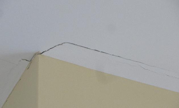
This type of movement goes by many different names that might sound familiar – truss arching, truss uplift, partition separation, or – to use the most formal name – ceiling-floor partition separation. All of these names describe the separation that develops between interior partition walls and ceiling finishes, which can cause gaps in the drywall to open in the winter and close in the summer. This movement is often considered to be a truss issue; however, it is not always the trusses that do the moving, but rather the walls or floors, or both, beneath the trusses.

This issue is also not limited to truss construction, but can also occur with other types of wood construction. The truss industry has information on this topic to help educate the market about the causes of ceiling-floor partition separation, best practices and construction techniques for minimizing the movement, and how to accommodate this movement in the structure to prevent drywall cracking.

trussmd1

For those who are interested in a very thorough and technical discussion of this issue and all of the factors that can contribute to it, there is a Technical Note available from the Truss Plate Institute (TPI) called Ceiling-Floor Partition Separation: What Is It and Why Is It Occurring? Although it was written several years ago (by the Small Homes Council-Building Research Council), the information remains relevant because the problem and its causes are the same now as they were then. The Technical Note discusses the potential causes of ceiling-floor partition separation, which may include one or more of the following: attic moisture (and the differential shrinkage and swelling of truss chords due to seasonal changes in moisture content), foundation settlement, expansive soils, excessive cumulative shrinkage of wood framing members and errors made during the construction process such as pulling the camber out of a truss to attach it to a partition. There is even an Appendix with a brief discussion of longitudinal shrinkage and an example calculation showing how much upward deflection results when a truss arches because of differential shrinkage.

For a condensed version, there is also a document available from the Structural Building Components Association (SBCA) called “Partition Separation Prevention and Solutions (How to Minimize Callbacks Due to Gypsum Cracking at the Wall/Ceiling Interface)”. This single-page document is particularly useful for educating the industry to take the appropriate preventive measures during construction, which help minimize problems later.

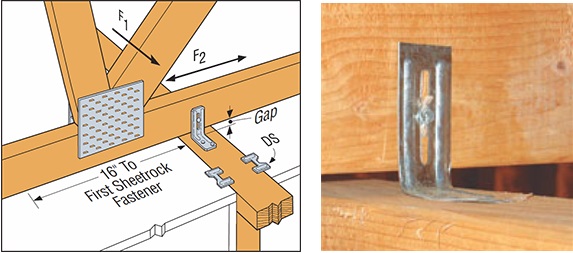
For example, the use of slotted roof truss clips – such as our STC (see below) – is one preventive measure, since these clips allow for vertical movement, but still provide lateral support at the top of the wall. DS drywall clips can be used in conjunction with the STC clips to secure the drywall to the wall. Then, to allow the drywall ceiling to “float,” the drywall is not fastened to the bottom chord within 16” from the wall. Taking these steps allows movement between the truss and the wall, without causing cracking in the drywall at the wall/ceiling interface.

trussmd2

It is important to note that, while foundation settlement may indicate a structural problem and can be prevented by proper design, truss arching resulting from the natural shrinking/swelling of wood does not indicate any structural problem and cannot be avoided in the design process.

Horizontal Movement of Scissor Trusses

In the typical design of a scissor truss, a pin-type bearing is used at one end, and a roller-type bearing is used at the other end, which results in some amount of horizontal deflection at the roller bearing.

trussmd3

trussmd4

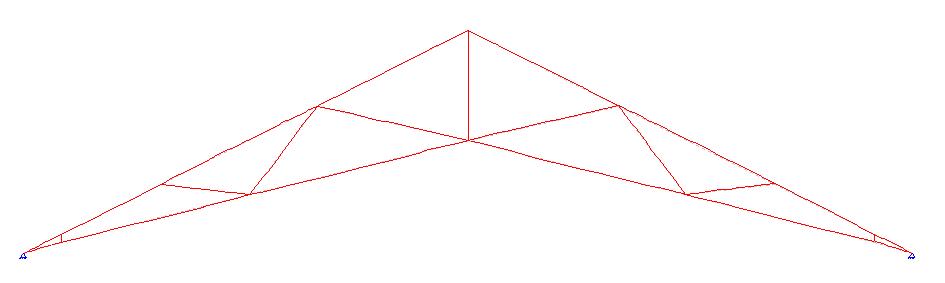
The bearing assumptions used in the design of a scissor truss are important not only to the truss, but they also have design implications for the building as well. Using a pin-type bearing at both ends of the truss has undoubtedly been a temptation to every truss technician at one time or another, when the same scissor truss that is failing the analysis suddenly works as soon as the bearings are switched from pin-roller to pin-pin. Unfortunately, that isn’t a valid option unless the walls are infinitely stiff (which they typically aren’t), or unless special measures are taken to resist the horizontal thrust that develops at the pinned reactions. In most cases, such measures won’t be taken which means with the exception of some rare cases, scissor trusses must be designed with pin-roller bearings.

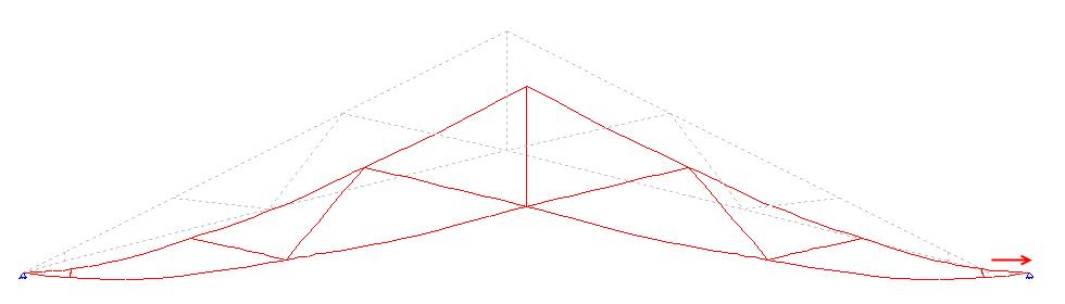
The horizontal deflection that results when a scissor truss is designed with a roller bearing on one end prompts further questions and discussion. What happens when a scissor truss is rigidly secured to the walls of the building – how does that horizontal movement happen? How much horizontal movement is too much? Should the scissor truss be attached to the wall with a sliding (roller-like) connection?

First, a scissor truss that is rigidly secured to both walls will still experience horizontal movement due to the flexibility of the building’s construction in most residential and light commercial construction. How much horizontal movement is too much for the building? This is definitely a question that the Building Designer needs to answer based on his/her evaluation of the overall structure. However, there are a couple of resources that can provide some insight.

ANSI/TPI 1 has the following provision:

trussmd5

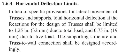
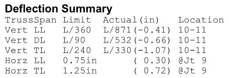
Per ANSI/TPI 1, a scissor truss can have up to 1.25″ of total horizontal deflection in the absence of stricter limits from the Building Designer. Scissor trusses may even be designed with more than this amount of horizontal deflection, along with a warning that special provisions for lateral movement may be required. It is important for the Building Designer to be aware of the calculated horizontal movement of the scissor truss, as reported on the truss design drawing, to ensure that it is an acceptable amount of horizontal movement for the supporting structure and/or to determine whether special provisions for the lateral movement need to be made.

trussmd6

While 1.25″ of total horizontal deflection may seem like a lot of horizontal movement, these calculated horizontal deflections are considered to be conservative; many Designers agree that the predicted movement from the pin-roller bearing combination is greater than will actually occur in the constructed building. This is based on the fact that the design loads may be overstated and the contribution of the sheathing (and drywall if applicable) to resist the horizontal movement is not taken into account during the analysis of the truss.

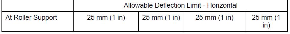
The National Building Code of Canada (NBC) references Section 5.4.4 of the 2009 Engineering Guide for Wood Frame Construction, which limits lateral movement at the top of each wall to h/500. This correlates to a total allowable horizontal movement of 3/8″ for 8ˈ walls. However, the Canadian truss design standard (TPIC-2014) permits trusses to have a horizontal deflection (at the roller support) of up to 1″. In this case, since the horizontal deflection of the truss exceeds the allowable horizontal deflection of the wall, a sliding connection needs to be used between the truss and the wall.

trussmd7

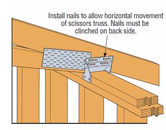
There are different opinions on the use of sliding connections, such as the slotted TC24 or TC26 connectors (see below), which allow for horizontal movement of the trusses without pushing out the wall, and also provide uplift resistance. The use of these clips also varies greatly by region. There are many places where these clips are used regularly and successfully. However, some Designers prefer to restrict the truss horizontal deflection and require the use of a positive connection between the scissor truss and the wall plate due to concerns regarding the transfer of lateral loads from the top of wall to the roof diaphragm. When TC connectors are used, they are often used on alternating ends of the trusses so that there is a positive connection along each wall at every other truss. Some Designers feel this approach minimizes the horizontal movement between the truss and the wall after the building is constructed and fully sheathed and braced.

trussmd8

There is not a single correct answer to address horizontal truss movement for every building. The amount of horizontal movement that is acceptable for the structure and whether or not a sliding connection should be used will depend on the building, the loading conditions, the designer’s experience and/or judgment, and, in some cases, the local building jurisdiction. What is more important than the decision to either restrict horizontal deflection or utilize sliding connectors like the TC24/TC26 (both have been successful) is that the bearing assumptions used in the design of the scissor truss are accounted for in the design of the building. The worst-case scenario is when a scissor truss is designed with a pin-pin bearing and installed in a building where absolutely no measures have been taken to supply the needed resistance to the calculated horizontal thrust.

What are your thoughts or experiences with either seasonal up-and-down movement or horizontal movement?  Let us know in the comments below!
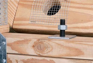
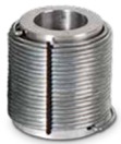
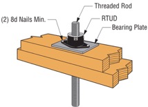
Masonry Reinforcement and Concrete Strengthening with Composites

Guest blogger Brad Erickson, Engineering Manager: Composite Strengthening Systems™
Guest blogger Brad Erickson, Engineering Manager

This week’s post comes from Brad Erickson, who is the Engineering Manager for the Composite Strengthening Systems™ product line at our home office. Brad is a licensed civil and structural engineer in the State of California and has worked in the engineering field for more than 17 years.  After graduating from Cal Poly, San Luis Obispo with a B.S. in Architectural Engineering, he worked for Watry Design, Inc. as an Associate Principal before coming to Simpson Strong-Tie.  Brad is the Engineering Manager for Composite Strengthening Systems and his experience includes FRP design, masonry and both post-tensioned and conventional concrete design.  While not at work, Brad enjoys spending time carting his three kids around to their competitive soccer games and practices.

Have you ever had a concrete or masonry design project where rebar was left out of a pour? Chances are, the answer is yes. Did you wish you could solve this problem by putting rebar on the outside of that element? That’s exactly what Simpson Strong-Tie Composite Strengthening Systems™ (CSS) can do for you and your project. In effect, composites act like external rebar for your concrete or masonry element. Composites can be used in similar configurations to rebar but are applied on the exterior surface of the element being strengthened.

The initial offering in our CSS line is our fiber-reinforced polymer (FRP) product group. An FRP composite is created by taking carbon or glass fabric and saturating it with a two-part epoxy which, when cured, creates the composite. Together, the weight of the fabric and the number of layers in the composite determine how much strength it will add to your concrete or masonry element.

reinforce1 Another form of FRP composite is a precured carbon laminate. The carbon fibers are saturated in the manufacturing facility and are attached to the structure using CSS-EP epoxy paste and filler, an epoxy with a peanut butter–like consistency. We also carry paste profilers (pictured below) that help contractors apply the proper amount of paste to a piece of precured laminate.

reinforce2Of course, before any concrete or masonry reinforcement project can succeed, proper surface preparation is of the utmost importance. Without a good bond with the substrate, a composite will not be able to achieve the intended performance. Concrete voids must be repaired, cracks must be injected and sealed, and any deteriorated rebar must be cleaned and coated. Prior to composite placement, the surface of the substrate must be prepared to CSP-3 (concrete surface profile) in accordance with ICRI Guideline No. 310.2. Grinding and blasting are the most common surface-preparation techniques.

reinforce3The following are just a few applications where composites can be used for concrete and/or masonry retrofits. The orange arrows show the direction of the fibers in the fabric – in other words, the direction in which the composite provides tension reinforcement.

FRP Confinement
reinforce5
Flexural Strengthening
Shear Strengthening
Shear Strengthening
Wall Flexural Strengthening

This is a summary of the basics of composites and their installation on strengthening projects. As composites are not yet in the design codes in the United States, the American Concrete Institute has produced 440.2R-08: Guide for the Design and Construction of Externally Bonded FRP Systems for Strengthening Concrete Structures. This guide has numerous recommendations for using fiber-reinforced polymer systems to strengthen your concrete or masonry construction.

If you would like more information about FRP design, you can learn the best practices for fiber-reinforced polymer (FRP) strengthening design during a recorded webinar offered by Simpson Strong-Tie Professional Engineers. We look at FRP components, applications and installation. We also take you behind the scenes to share the evaluation process informing a flexural beam-strengthening design example and talk about the assistance and support Simpson Strong-Tie Engineering Services offers from initial project assessment to installation.

Learn more: Webinar – Introducing Fabric-Reinforced Cementitious Matrix (FRCM)

In this free webinar we dive into some very important considerations including the latest industry standards, material properties and key governing limits when designing with FRCM.

Continuing education credits will be offered for this webinar.
Participants can earn one professional development hour (PDH) or 0.1 continuing education unit (CEU).


For complete information regarding specific products suitable to your unique situation or condition, please visit strongtie.com/rps or call your local Simpson Strong-Tie RPS specialist.