Designing post-installed anchorage near a concrete edge is challenging, especially since the ACI provisions for cracked-concrete anchorage went into effect. In the following post, one of our field engineers, Jason Oakley, P.E., explains how SET-3G™ and Anchor Designer™ software from Simpson Strong-Tie make it easier to design a ductile anchor solution.
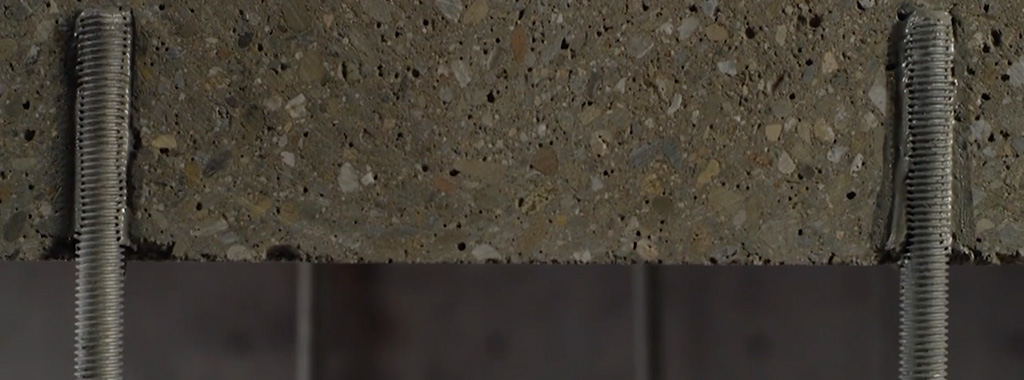
Engineers often provide holdown anchoring solutions near a concrete edge to help prevent overturning of light-frame shear walls during a seismic (or high-wind) event. Sometimes a post-installed anchor must be used if the cast-in-place anchor was mislocated or misinstalled, or is located where a retrofit or addition is needed. Since the cracked-concrete anchorage design provisions went into effect more than a decade ago, it has been challenging for engineers to offer a near-edge post-installed anchoring solution. This is especially true for structures subject to earthquake loads in seismic design category (SDC) C through F. Simpson Strong-Tie’s new SET-3G epoxy is the first anchoring adhesive in the industry to offer exceptionally high bond-strength values that permit ductile anchorage in concrete near an edge. This blog post will cover a specific example that focuses on Chapter 17 of ACI 318-14 to design a threaded rod, anchored with SET-3G adhesive, used to secure a holdown located 1 3/4″ away from a single concrete edge (Figure 1). Continue Reading
This week’s post was written by Jhalak Vasavada, Research & Development Engineer at Simpson Strong-Tie.
When we launched our new, patent-pending MPBZ moment post base earlier this year, the evaluation of the moment capacity of post bases was not covered by AC398 – or by any other code, for that matter. There wasn’t a need – there were no code-accepted connectors available on the market for resisting moment loads. Continue Reading
It’s been said that the World Wide Web is the wave of the future. Okay, maybe this is slightly outdated news, as it’s been 25 years since Bill Gates penned his internet tidal-wave memorandum, but it’s a good lead-in to this week’s blog topic – web apps. More specifically, those apps that have been developed to address the wall-bracing requirements defined in the International Residential Code® (IRC). Designers and engineers have no doubt noticed that over the last several code cycles, the wall-bracing provisions in the IRC have become increasingly complex. To help navigate these requirements and calculate the required bracing length for a given wall line, Simpson Strong-Tie introduced the Wall-Bracing-Length Calculator (WBLC) a few years back, as discussed in an earlier blog post. I’ll also mention that the WBLC has since been updated to the 2015 IRC. Continue Reading
In March of 2016, the United States Department of Labor issued new OSHA standards on how crystalline silica dust should be handled in various workplaces including within the construction industry. The changes are intended to limit workers’ exposure to and inhalation of silica dust on the jobsite. These regulations will replace the current standard, which was issued in 1971. Compliance with the new rules will be required on construction jobsites starting September 23, 2017, and will be enforced through OSHA from that time forward. Continue Reading
This blog post will continue our series on the final results of the 2016 ICC Group B Code Change Hearings, and will focus on 10 major approved changes, of a structural nature, to the International Building Code (IBC).
Adoption of ASCE 7-16
The IBC wind speed maps and seismic design maps have been updated.
A new section has been added to Chapter 16 to address tsunami loads.
Table 1607.1 has been revised to change the deck and balcony Live Loads to 1.5 times that of the occupancy served.
New and Updated Reference Standards
2015 IBC Standard ACI 530/ASCE 5/TMS 402-13 will be TMS402-16.
AISC 341-10 and 360-10 have both been updated to 2016 editions.
AISI S100-12 was updated to the 2016 edition.
AISI S220-11 and S230-07 were updated to the 2015 edition.
AISI S200, S210, S211, S212 and S214 have been combined into a new single standard, AISI S240-15.
AISI S213 was split into the new S240 and AISI S400-15.
ASCE 41-13 was updated to the 2017 edition.
The ICC 300 and ICC 400 were both updated from 2012 editions to 2017 editions.
ANSI/NC1.0-10 and ANSI/RD1.0-10 were all updated to 2017 editions.
Section 1607.14.2 Added for Structural Stability of Fire Walls
This new section takes the 5 psf from NFPA 221, so designers will have consistent guidance on how to design fire walls for stability without having to buy another standard.
Modifications of the IBC Special Inspections Approved
Section 1704.2.5 on special inspection of fabricated items has been clarified and streamlined.
The Exception to 1705.1.1 on special inspection of wood shear walls, shear panels and diaphragms was clarified to say that special inspections are not required when the specified spacing of fasteners at panel edges is more than 4 inches on center.
The special inspection requirements for structural steel seismic force-resisting systems and structural steel elements in seismic force-resisting systems were clarified by adding exceptions so that systems or elements not designed in accordance with AISC 341 would not have to be inspected using the requirements of that standard.
Changes Pertaining to Storm Shelters
A new Section 1604.11 states that “Loads and load combinations on storm shelters shall be determined in accordance with ICC 500.”
An exception was added stating that when a storm shelter is added to a building, “the risk category for the normal occupancy of the building shall apply unless the storm shelter is a designated emergency shelter in accordance with Table 1604.5.”
Further clarification in Table 1604.5 states that the type of shelters designated as risk category IV are “Designated emergency shelters including earthquake or community storm shelters for use during and immediately after an event.”
Changes to the IBC Conventional Construction Requirements in Chapter 23
The section on anchorage of foundation plates and sills to concrete or masonry foundations reorganized the requirements by Seismic Design Category (SDC) and added a new section on anchoring in SDC E. It also states that the anchor bolt must be in the middle third of the width of the plate and adds language to the sections on higher SDCs saying that if alternate anchor straps are used, they need to be spaced to provide equivalent anchorage to the specified 1/2″- or 5/8″-diameter bolts.
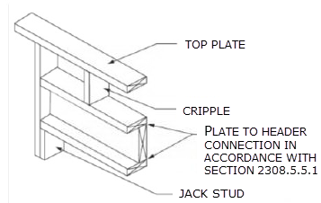
The second change permits single-member 2-by headers, to allow more space for insulation in a wall.
Modification to the Requirements for Nails and Staples in the IBC
ASTM F1667 Supplement One was adopted that specifies the method for testing nails for bending-yield strength and identifies a required minimum average bending moment for staples used for framing and sheathing connections.
Stainless-steel nails are required to meet ASTM F1667 and use Type 302, 304, 305 or 316 stainless steel, as necessary to achieve the corrosion resistance assumed in the code.
Staples used with preservative-treated wood or fire-retardant-treated wood are required to be stainless steel.
The new RSRS-01 nail was incorporated into TABLE 2304.10.1, the Fastening Schedule. The RSRS nail is a new roof sheathing ring shank nail designed to achieve higher withdrawal resistances, in order to meet the new higher component and cladding uplift forces of ASCE 7-16.
Truss-Related Code Change
The information required on the truss design drawings was changed from “Metal connector plate type” to “Joint connection type” in recognition that not all trusses use metal connector plates.
Code Change to Section 2304.12.2.2
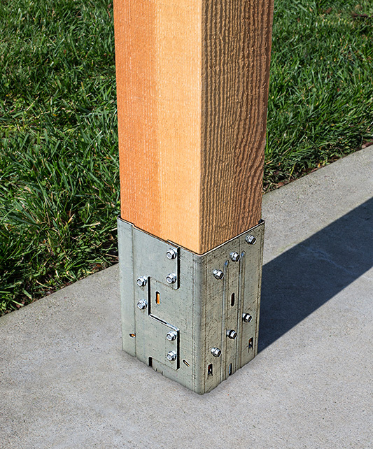
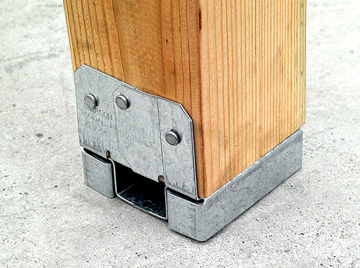
A code change clarifies in which cases posts or columns will not be required to consist of naturally durable or preservative-treated wood. This change makes the requirements closer to the earlier ones, while maintaining consistency with the subsequent section on supporting members.
If a post or column is not naturally durable or preservative-treated, it will have to be supported by concrete piers or metal pedestals projecting at least 1″ above the slab or deck, such as Simpson Strong-Tie post bases that have a one-inch standoff.
Code Change to IBC Appendix M
A code change from FEMA makes IBC Appendix M specific to refuge structures for vertical evacuation from tsunami, and the tsunami hazard mapping and structural design guidelines of ASCE 7-16 would be used rather than those in FEMA P-646.
Once the 2018 IBC is published in the fall, interested parties will have only a few months to develop code changes that will result in the 2021 I-Codes. Similar to this last cycle, code changes will be divided into two groups, Group A and Group B, and Group A code changes are due January 8, 2018. The schedule for the next cycle is already posted here.
What changes would you like to see for the 2021 codes?
He huffed, and he puffed, and he blew the roof sheathing off! That’s not the way kids’ tale goes, but the dangers high winds pose to roof sheathing are very real. Once the roof sheathing is gone, the structure is open and its contents are exposed to the elements and much more vulnerable to wind or water damage. It is a storyline that we meet all too often in the news.
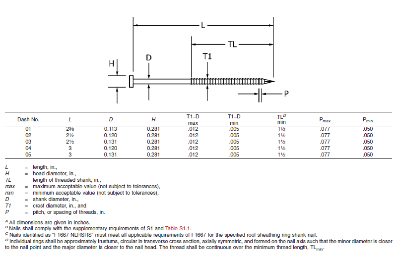
About two years ago, the ASTM subcommittee on Driven and Other Fasteners (F16.05), addressed fastening for roof sheathing in high-wind areas by adding a special nail to ASTM F1667-17 – Standard Specification for Driven Fasteners: Nails, Spikes and Staples. The Roof Sheathing Ring-Shank Nail was added to the standard as Table 46. Figure 1 illustrates the nail and lists its geometrical specifications. This is a family of five ring-shank nails that can be made from carbon steel or stainless steel (300 series). Specific features of these nails are the ring pitch (number of rings per inch), the ring diameter over the shank, the length of deformed shank and the head diameter. Also, note B specifies that the nails shall comply with the supplementary requirement of Table S1.1, which tabulates bending yield strength. In this diameter class, the minimum bending yield strength allowed is 100 ksi.
Figure 1. Roof Sheathing Ring-Shank Nails (ASTM. 2017. Standard Specification for Driven Fasteners: Nails, Spikes and Staples, F1667-17. ASTM International, West Conshohocken, PA.)
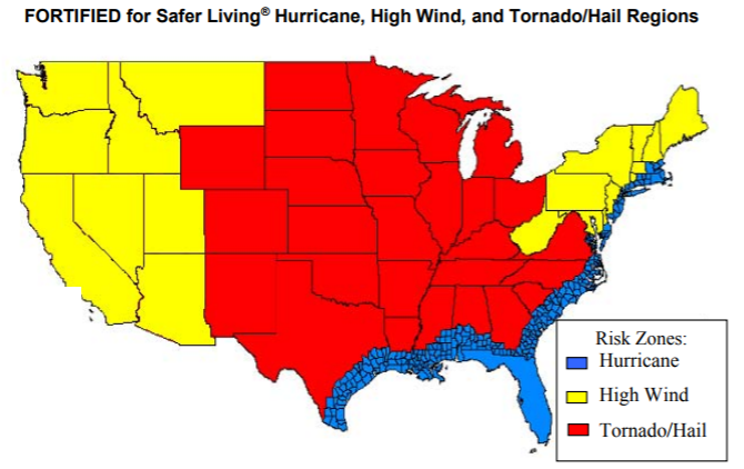
The IBHS (Insurance Institute for Business and Home Safety) discusses roof deck fastening in its Builders Guide that describes the “FORTIFIED for Safer Living” structures. The IBHS FORTIFIED program offers solutions that reduce building vulnerability to severe thunderstorms, hurricanes and tornadoes. Keeping the roof sheathing on the structure is critical to maintaining a safe enclosure and minimizing damage, and roof sheathing ring-shank nails can be part of the solution. As Figure 2 from IBHS (2008) shows, every wood-frame structure has wind vulnerability.
Figure 2. Hurricane, high wind and tornado regions of the US (IBHS. 2008. Builders Guide, Fortified for Safer Living. Tampa, FL. 81 pp.)
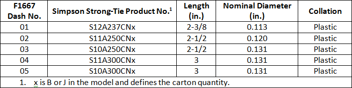
More importantly for the wood-frame engineering community, the Roof Sheathing Ring-Shank Nails are being included in the next revision of the AWC National Design Specification for Wood Construction (NDS-2018), which is a reference document to both the International Building Code and the International Residential Code. You will be able to use the same NDS-2018, chapter 12 withdrawal equation to calculate the withdrawal resistance for Roof Sheathing Ring-Shank Nails and Post Frame Ring-Shank nails. The calculated withdrawal will be based on the length of deformed shank embedded in the framing member. Also, Designers need to consider the risk of nail head pull-through when fastening roof sheathing with ring-shank nails. If the pull-through for roof sheathing ring-shank nails is not published, you will be able to use the new pull-through equation in the NDS-2018 to estimate that resistance. Simpson Strong-Tie has some stainless-steel products that meet the requirements for Roof Sheathing Ring-Shank Nails. These will be especially important to those in coastal high-wind areas. Table 1 shows some of the Simpson Strong-Tie nails that can be used as roof sheathing ring-shank nails. These nails meet the geometry and bending yield strength requirements given in ASTM F1667. See the Fastening Systems catalog C-F-2017 for nails in Type 316 stainless steel that also comply with the standard.
Table 1. Simpson Strong-Tie collated nails made from Type 304 stainless steel that comply with F1667-17 specifications for Roof Sheathing Ring-Shank Nails.
Improve your disaster resilience and withstand extreme winds by fastening the sheathing with roof sheathing ring-shank nails. You can find Roof Sheathing Ring-Shank nails in ASTM F1667, Table 46, and you will see them in the AWC NDS-2018, which will be available at the end of the year. Let us know your preferred fastening practices for roof sheathing.
The wait is over. The ACI 440.2R-17 Guide for the Design and Construction of Externally Bonded FRP Systems for Strengthening Concrete Structures is now available. The following post will highlight some of the major changes represented by this version of the document.
It’s been a long road and countless committee hours to get from the last version of ACI 440.2R-08 to this document. While there are multiple smaller changes throughout the document, the most notable update is the addition of Chapter 13 – Seismic Strengthening.
The new seismic chapter addresses the following FRP strengthening scenarios:
Section 13.3 – Confinement with FRP
This section includes all of the following: general considerations; plastic hinge region confinement; lap splice clamping; preventative buckling of flexural steel bars.
Section 13.4 – Flexural Strengthening
The flexural capacity of reinforced concrete beams and columns in expected plastic hinge regions can be enhanced using FRP only in cases where strengthening will transfer inelastic deformations from the strengthened region to other locations in the member or the structure that are able to handle the ensuing ductility demands.
Section 13.5 – Shear Strengthening
To enhance the seismic behavior of concrete members, FRP can be used to prevent brittle failures and promote the development of plastic hinges.
Section 13.6 – Beam-Column Joints
This section covers a great deal of recent research on the design and reinforcement of beam-column joints.
This section provides many recommendations for FRP strengthening of R/C shear walls.
Simpson Strong-Tie Can Help
We recognize that specifying Simpson Strong-Tie® Composite Strengthening Systems™ (CSS) is unlike choosing any other product we offer. Leverage our expertise to help with your FRP strengthening designs. Our experienced technical representatives and licensed professional engineers provide complimentary design services and support – serving as your partner throughout the entire project cycle.
For complete information regarding specific products suitable to your unique situation or condition, please visit strongtie.com/cssor call your local Simpson Strong-Tie RPS Specialist at (800) 999-5099.
Join us live on July 25 for the second interactive webinar in the Simpson Strong-Tie FRP Best Practices Series: Advanced FRP Design Principles. In this webinar we will highlight some very important considerations during the FRP design processes. This will include topics such as the latest industry standards, proper use of material properties, and key governing limits when designing with FRP. Attendees will also have an opportunity to pose questions to our engineering team during the event. Continuing educations units will be offered for attending this webinar.
In this free webinar we dive into some very important considerations including the latest industry standards, material properties and key governing limits when designing with FRCM.
Continuing education credits will be offered for this webinar. Participants can earn one professional development hour (PDH) or 0.1 continuing education unit (CEU).
Experiential learning — has it happened to you? Certainly it has, because experiential learning is learning derived from experience. It happens in everyday life, in engineering and in product development, too. For example, experience has taught us that after a product is launched, our customers will find applications for the product that were never expected or listed in the product brief. Also, experience has shown us that larger fasteners tend to be placed in applications that have greater structural and safety demands.
When the larger Deck-Drive™ DWP screws were manufactured, we decided that they should be marketed as “load-rated” screws because they were big enough to support physically large parts and would be expected to provide structural load resistance.
So what is a “load-rated” screw? To Simpson Strong-Tie, a load-rated screw is a threaded fastener that has controlled dimensions and physical properties, as well as validated connection properties. Load-rated fasteners are also subject to the same quality inspection that would occur if they were undergoing an evaluation report.
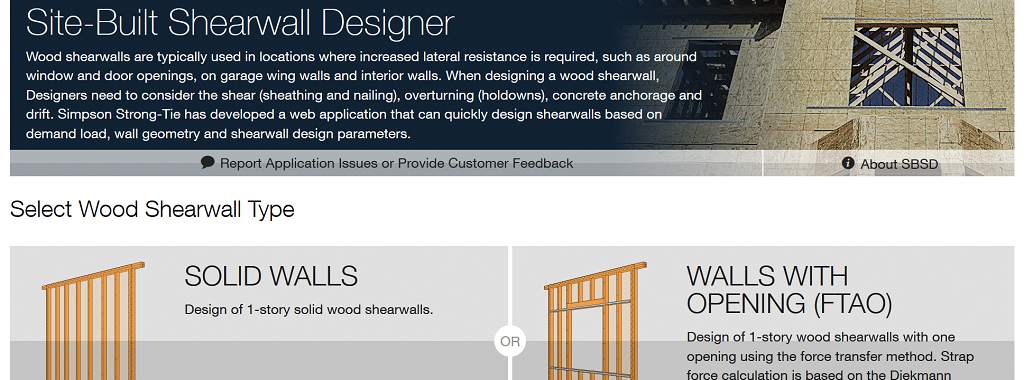
Wood shearwalls are typically used as a lateral-force-resisting system to counter the effects of lateral loads. Wood shearwalls need to be designed for shear forces (using sheathing and nailing), overturning (using holdowns), sliding (using anchorage to concrete) and drift, to list some of the main dangers. The Simpson Site-Built Shearwall Designer (SBSD) web app is a quick and easy tool to design a wood shearwall based on demand load, wall geometry and design parameters.Continue Reading
How would a six-story light-frame wood building perform in a large earthquake? Back in 2009, Simpson Strong-Tie was a partner in the World’s Largest Earthquake Test, a collaboration of the NEESWood project, to answer that question. This was a full-scale test which subjected the building to 180% of the Northridge earthquake ground motions (approximately a M7.5). Within the building, Simpson Strong-Tie connectors and Strong-Frame SMF were used, with the Strong-Rod™ anchor tiedown system (ATS) serving as holdown for each shearwall.
The NEESWood building was designed under Performance-Based Design methodology, and the test was conducted as validation for the approach. Buildings of similar size to the NEESWood building are built to current codes using similar products. Mid-rise light-frame wood structures continue to be a popular form of construction in various densely populated cities across the country. As part of the lateral-force-resisting system, continuous rod systems are used as the holdown for the shearwall overturning restraints. Simpson Strong-Tie has been involved with continuous rod systems since the early 2000s when we launched the Strong-Rod anchor tiedown system.
Today, rod manufacturers design the continuous rod systems with design requirements (loading, geometry, etc.) Supporting documents (e.g., installation details, layouts, RFI/markups and calculations) are submitted for each unique project. Over the years, engineers have asked many questions related to the design of these systems. In this week’s blog, we will explore Frequently Asked Questions pertaining to Strong-Rod ATS systems used as shearwall overturning restraints (holdowns).
The majority of these components are designed in accordance with the building code and reference standards (e.g., NDS, AISC). A project-specific calculation package is submitted for each job that addresses the evaluation of these elements. Therefore, these elements are not listed in evaluation reports.
Shrinkage compensation devices, on the other hand, are proprietary components which are not addressed by the building code or reference standards. Therefore, they are tested in accordance with ICC-ES acceptance criteria AC316 and are listed in ICC-ES ESR-2320.
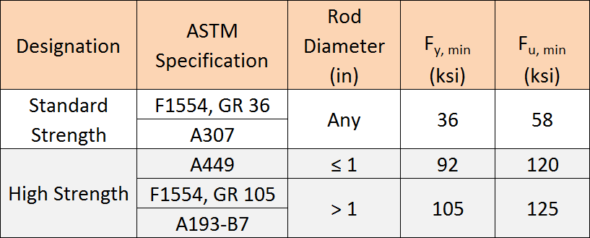
What is the material specification of the rods used above concrete?
The specified rod materials are shown in Table 1.
Table 1. ATS Rod Material Specifications
Can threaded rods or couplers be welded to steel beams?
Simpson Strong-Tie generally does not recommend this practice. Of the materials listed in Table 1, ASTM A307 material is the only specification that contains supplementary requirements for welding. When standard strength rod is supplied to the job, it is not guaranteed that this will be the material provided.
ASTM A449 and A193-B7 high-strength rods develop strength and ductility characteristics through controlled quenching and tempering treatments. Quenching is the rapid cooling of metal (usually by water or oil) to increase toughness and strength. This process often increases brittleness. Tempering is a controlled reheating of the metal which increases ductility after the quenching process. Precise timing in the application of temperature during the tempering process is critical to achieving a material with well-balanced mechanical properties. It is unlikely that field welding will satisfy the requirements of quenching and tempering.
Coupler nuts are generally fabricated from material exhibiting characteristics similar to high-strength rods. Thus, it is not recommended to weld coupler nuts to steel beams due to the potential for embrittlement.
Simpson Strong-Tie specifies a weldable cage which is fabricated from ASTM A36 material for such applications.
How do you calculate the Maximum ASD Tension Capacity provided in the job summary?
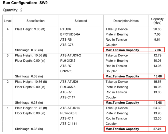
Simpson Strong-Tie provides a comprehensive design package for continuous rod systems used as holdowns for multi-story stacked shearwalls. The individual run calculations, as shown in Figure 1, provide the Maximum Tension Capacity, which correlates to the maximum force the system can deliver. Plan check often requests justification on how these values are derived at each level. These values are calculated, and the process explained below may be used on any Simpson Strong-Tie ATS Job Summary as justification.
Figure 1. Sample ATS Run Type SW9
The maximum tension capacity published within the Job Summary and the Installation Details is derived using the following procedure:
Step 1: Evaluate the top-most level. Compare the published capacities of the rod in tension, plate in bearing and the take-up device. The lowest of these three will govern and becomes the Maximum Tension Capacity for this level.
Step 2: Evaluate the next level down. (a) Sum the Maximum Tension Capacity from Step 1 and the published capacity of the take-up device from this level. (b) Sum the Maximum Tension Capacity from Step 1 and the published capacity of the plate in bearing from this level. (c) Compare derived values from (a) and (b) to the published capacity of rod in tension. The lowest of these three values will govern and becomes the Maximum Tension Capacity of this level.
Step 3: Repeat Step 2 as necessary until the bottom-most level is reached.
Applying this procedure to the sample run, SW9, will wield the following result:
Step 1: Evaluate capacities published at Level 4
Plate in bearing (PBRTUD5-6A) = 7.06 kipsgoverns
Take-up device (RTUD6) = 20.83 kips
Rod in tension (ATS-R6) = 9.61 kips
The lowest value in Step 1 is the plate in bearing, hence 7.06 kips is the maximum load that can be delivered at Level 4 and is the Maximum Tension Capacity.
Step 2: Evaluate capacities at Level 3
Maximum Tension Capacity from Level 4 = 7.06 kips (See Step 1)
Maximum Tension Capacity from Level 4 + take-up device (ATS-ATUD9-2) = 7.06 + 12.79 = 19.85 kips
Maximum Tension Capacity from Level 4 + plate in bearing (PL9-3×5.5) = 7.06 + 10.03 = 17.09 kips
Rod in tension (ATS-R7) = 13.08 kipsgoverns
The lowest value in Step 2 is the rod in tension, hence 13.08 kips is the maximum load that can be delivered at Level 3 and is the Maximum Tension Capacity.
Step 3: Evaluate capacities at Level 2
Maximum Tension Capacity from Level 3 = 13.08 kips (See Step 2)
Maximum Tension Capacity from Level 3 + take-up device (ATS-ATUD9-2) = 13.08 + 15.56 = 28.64 kips
Maximum Tension Capacity from Level 3 + plate in bearing (PL9-3×5.5) = 13.08 + 10.03 = 23.11 kips
Rod in tension (ATS-R7) = 13.08 kipsgoverns
The lowest value in Step 3 is the rod in tension, hence 13.08 kips is the maximum load that can be delivered at Level 2 and is the Maximum Tension Capacity.
Step 4: Evaluate capacities at Level 1
Maximum Tension Capacity from Level 2 = 13.08 kips (See Step 3)
Maximum Tension Capacity from Level 2 + take-up device (ATS-ATUD14) = 13.08 + 24.39 = 37.47 kips
Maximum Tension Capacity from Level 2 + plate in bearing (PL14-3×8.5) = 13.08 + 13.98 = 27.05 kipsgoverns
Rod in tension (ATS-R11) = 32.30 kips
The lowest value in Step 4 is due to the plate in bearing, hence 27.05 kips is the maximum load that can be delivered at Level 1 and is the Maximum Tension Capacity.
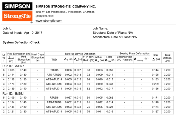
In the System Deflection Summary page(s) of the Job Summary, is the Total System Deflection provided at Allowable or Strength levels?
Immediately following the individual run calculations in each job summary, Simpson Strong-Tie provides a summary of deflection of the rod system similar to what is shown in Figure 2. This breaks down the deformation of all components being considered. In the example below, the rod elongation and deflection of the take-up device are summed to provide the total deflection.
The calculated system deflection is presented at ASD level. See section below for how to use these system deflections for your drift calculation.
Figure 2. Sample System Deflection Check
What system deflection limit do you typically design to, and what does that include?
Unless otherwise specified on the plans or required by the building jurisdiction, Simpson Strong-Tie will design the continuous rod system to satisfy the deformation limits set forth in ICC-ES Acceptance Criteria (AC316). In some instances, the Designer may need a more restrictive deformation due to project specific conditions (e.g., tight building separations) and will require rod manufacturers to design for a lower deformation. Some jurisdictions (e.g., City of San Diego, City of San Francisco) may also have specific design requirements that continuous rod systems must conform to. The minimum recommended per-floor deformation limit set forth in AC316 is:
PD = ASD demand cumulative tension load (kips) L = length of the rod between restraints – i.e., floor-to-floor (in.) A = net tensile area of the rod (in.2) E = Young’s Modulus of Elasticity (29,000 ksi) ΔR = seating increment of the shrinkage compensation device (as published in ICC-ES evaluation report) ΔA = deflection of the shrinkage compensation device at the allowable load (as published in ICC-ES evaluation report) PA = Allowable capacity (kips)
Should deformation limits be specified in the construction documents?
Simpson Strong-Tie strongly recommends this information be included in the construction documents. Along with the cumulative tension and compression forces, the required deformation limits for the holdown are important to ensure that rod manufacturers are designing the holdown to satisfy the desired shearwall performance.
How do I use the system deformation limit?
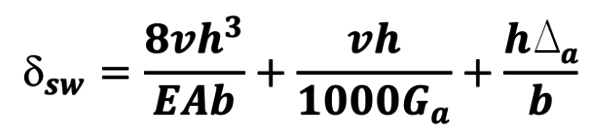
The System Deflection is the total deformation of the holdown system from floor to floor (refer to the last two columns in Figure 2). This information represents the total ASD holdown deformation term, Δa, for each level and is to be used in the shearwall drift equation from the Special Design Provisions for Wind and Seismic (2015 SDPWS 4.3-1).
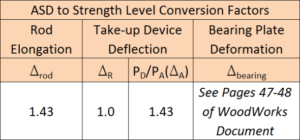
ASCE 12.8.6 requires that shearwall drift be calculated at strength level. Therefore, the information provided within the System Deflection Summary page needs to be converted from ASD to Strength Level. The conversion factors in Table 2 can be used to convert the ASD deformations to strength level. For discussions and methodology in converting bearing plate deformation to strength level, please refer to the WoodWorks Design Example of a Five-Story Wood Frame Structure over Podium Slab found here.
Table 2. ATS Rod Deflection ASD to LRFD Conversion Factors
Can rod systems be used in Type III construction?
Yes! 2015 IBC §2303.2.5 requires that Fire Retardant-Treated Wood (FRTW) design values be adjusted based on the type of treatment used on the project. Adjustment factors vary for each FRTW manufacturer; refer to the ICC-ES evaluation report of the specified FRTW manufacturer for the unique adjustment values. Rod manufacturers need to know what treatment is being used so this information can be taken into consideration when designing compression posts and incremental bearing (bearing plates).
What are Simpson Strong-Tie’s guidelines for fire caulking material?
While there are many options for fire-rated caulking, these products can be used in conjunction with the Simpson Strong-Tie ATS system. Below is a list of considerations when selecting and specifying a material for use where the rods penetrate the top and sole plates:
The fire-rated caulking shall not be corrosive to metal when used in contact with ATS components.
Direct contact with shrinkage compensating devices (e.g., TUD, ATUD, RTUD) shall be avoided. Shrinkage compensating devices have moving components and may not function properly with debris interference.
Indirect contact with shrinkage compensating devices shall also be avoided. Shrinkage compensation accumulates up the building and therefore the largest shrinkage occurs at the top of the building. As such, when the building shrinks, remnants of the material may still be stuck to the threads of the rod and may be detrimental to the performance of some shrinkage compensating devices (e.g., an RTUD). It is recommended to detail the installation with shrinkage taken into consideration.
The fire-rated caulking should be pliable to accommodate wood shrinkage and the building moving down during this process.
The performance and the suitability of fire-rated caulking are outside the scope of Simpson Strong-Tie.
Why doesn’t your design include compression post design?
If the Engineer of Record has already specified compression posts to be used with a continuous rod system, Simpson Strong-Tie will not provide these on the holdown installation drawings. This is primarily done to prevent discrepancies between the specification in the contract documents and what is shown on the installation drawings.
What is the maximum spacing between compression posts?
For platform-framed structures, the maximum spacing between compression posts is 9″. The large majority of Simpson Strong-Tie bearing plates will fit within the 9″ spacing requirement, eliminating the need for notching compression posts. In some framing conditions, such as balloon framing or a top chord bearing truss, the maximum spacing will be reduced to 6″. This is due to the limited amount of space between the top of the compression posts transferring uplift (via bearing) into the point of restraint (e.g., bearing plate) at the level above. To ensure this load path is complete, the posts need to be spaced closer.
What is the nailing schedule for the bridge block to the king studs?
Simpson Strong-Tie doesn’t recommend nailing the bridge block to the cripple as the bridge block member will shrink. Locking the bridge block in place may result in a gap forming between the bottom of the bridge block member and the top of the cripple studs, which is not accounted for in the Total System Deflection.
Are there any published documents with design examples of continuous rod systems used in mid-rise construction?
Another useful resource is published by WoodWorks and is a design example of a five-story wood-frame structure over podium slab. This document can be found here.
What questions do you have about the Strong-Rod ATS System? Leave them below.
We use cookies on this site to enhance your user experience. By clicking "I AGREE" below, you are giving your consent for us to set cookies. Privacy PolicyI AGREE
Privacy & Cookies Policy
Privacy Overview
This website uses cookies to improve your experience while you navigate through the website. Out of these cookies, the cookies that are categorized as necessary are stored on your browser as they are essential for the working of basic functionalities of the website. We also use third-party cookies that help us analyze and understand how you use this website. These cookies will be stored in your browser only with your consent. You also have the option to opt-out of these cookies. But opting out of some of these cookies may have an effect on your browsing experience.
Necessary cookies are absolutely essential for the website to function properly. This category only includes cookies that ensures basic functionalities and security features of the website. These cookies do not store any personal information.
Any cookies that may not be particularly necessary for the website to function and is used specifically to collect user personal data via analytics, ads, other embedded contents are termed as non-necessary cookies. It is mandatory to procure user consent prior to running these cookies on your website.