


This week’s post comes from Marlou Rodriguez who is an R&D Engineer at our home office. Prior to joining Simpson Strong-Tie, Marlou worked as a consulting engineer. His experience includes commercial, multi-family residential, curtain wall systems and the design of seismic bracing for non-structural components. Marlou is a licensed professional Civil and Structural Engineer in California, and too many other states to list. He received his bachelor’s degree in Architectural Engineering from Cal Poly San Luis Obispo. Here is Marlou’s post.Continue Reading
Category: In the Coffer
Not everything fits into an easy category. “In the Coffer” is where our engineers cut loose and talk about personal passions.
Holdown Anchorage Solutions
A common question we get from specifiers is “What anchor do I use with each holdown?” Prior to the adoption of ACI 318 Appendix D, this was somewhat simple to do. We had a very small table near the holdown section of our catalog that listed which SSTB anchor worked with each holdown.
During the good old days, anchor bolts had one capacity and concrete wasn’t cracked. ACI 318 Appendix D gives us reduced capacities in many situations, different design loads for seismic or wind and reductions for cracked concrete. These changes have combined to make anchor bolt design more challenging than it was under the 1997 Uniform Building Code.
This blog has had several posts related to holdowns. So, What’s Behind a Structural Connector’s Allowable Load? (Holdown Edition) explained how holdowns are tested and load rated in accordance with ICC-ES Acceptance Criteria. Damon Ho did a post, Use of Holdowns During Shearwall Assembly, which discussed the performance differences of shearwalls with and without holdowns, and Shane Vilasineekul did a Wood Shearwall Design Example. So I won’t get in to how to pick a holdown.
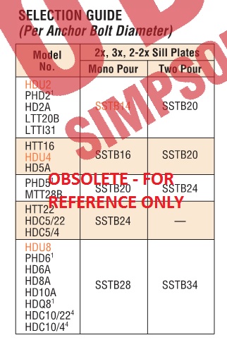
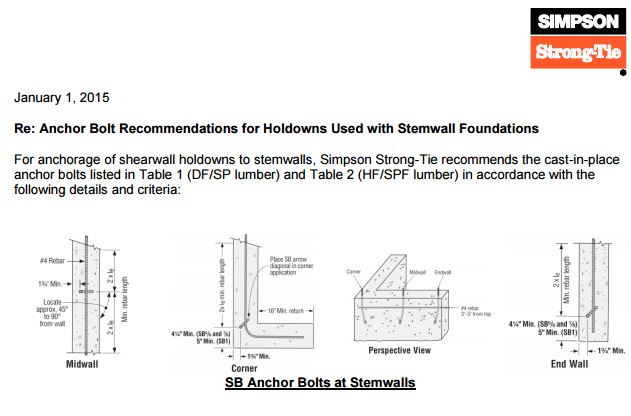
Once you have determined your uplift requirements and selected a post size and holdown, it is necessary to provide an anchor to the foundation. To help Designers select an anchor that works for a given holdown, we have created different tables that provide anchorage solutions for Simpson Strong-Tie holdowns.
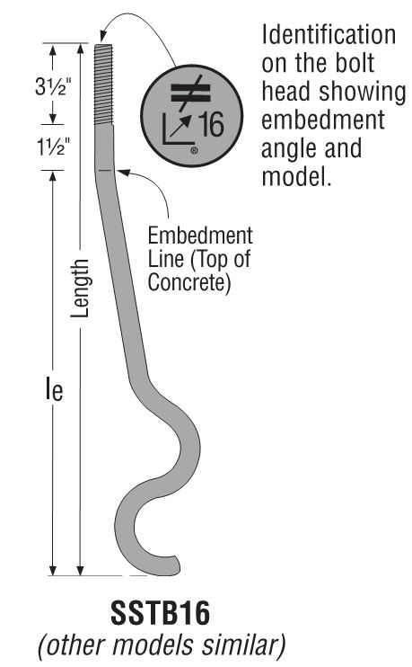
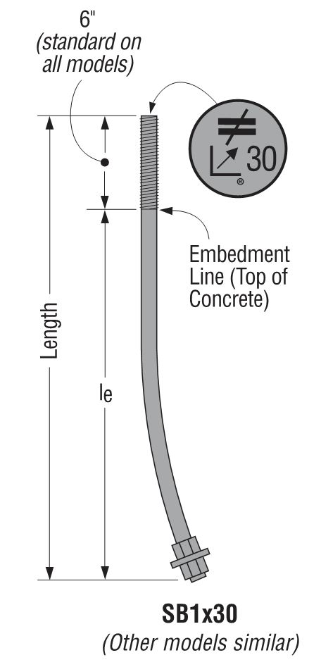
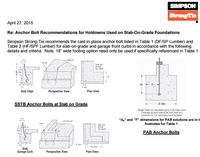
There is one Engineering letter that addresses slab-on-grade foundations and another version that covers stemwall foundations. The tables are separated by wood species (DF/SP and SPF/HF) to give the most economical anchor design for each post material. The preferred anchor solutions are SSTB or SB anchors, as these proprietary anchor bolts are tested and will require the least amount of concrete. When SSTB or SB anchors do not have adequate capacity, we have tabulated solutions for the PAB anchors, which are pre-assembled anchors that are calculated in accordance with ACI 318 Appendix D.
The solutions in the letters are designed to match the capacity of the holdowns, which allows the contractor to select an anchor bolt if the engineer doesn’t specify one. They are primarily used by engineers who don’t want to design an anchor or select one from our catalog tables. We received some feedback from customers who were frustrated that some of our heavier holdowns required such a large footing for the PAB anchors, whereas a slightly smaller holdown worked with an SB or SSTB anchor in a standard 12″ footing with a 1½” pop out.
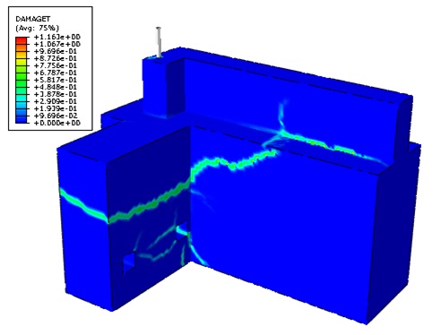
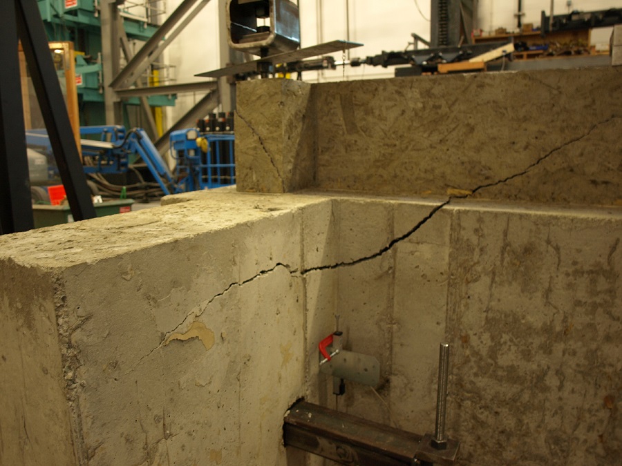
To achieve smaller footings using our SB1x30 anchor bolts, we reviewed our original testing and created finite element (FEA) models to determine what modifications to the slab-on-grade foundation details would meet our target loads. Of course, we ran physical tests to confirm the FEA models. With a 6″ pop out, we were able to achieve design loads for HD12, HDU14 and HHDQ14.
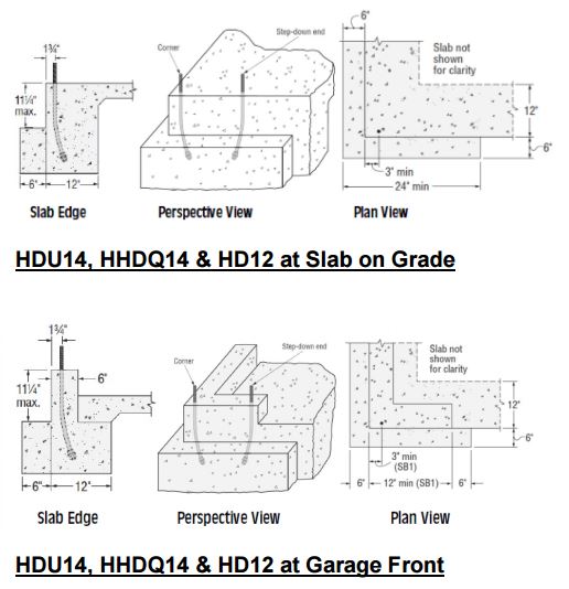
The revised footing solutions for the heavier holdowns require less excavation and less concrete than the previous Appendix D calculated solutions, reducing costs on the installation.
What has been your experience with holdown anchorage? Tell us in the comments below.
Happy Holidays!
Happy holidays from Simpson Strong-Tie. We hope that when you build that gingerbread house, you think of building it with a continuous load path for a safer, structurally sound building. Please check back Jan 8 for our regularly scheduled posts. 
Why Social Media Matters for Structural Engineers

We have written posts before about how social media can help you grow your business and how it can make you better at your job. But the main question you may still be asking is “why social media?” Isn’t it just a place to view cat videos or chat with friends?
While you can use social media for personal reasons, it has now become a serious source of professional content that can help make your life as a structural engineer a little easier. Here are some reasons why social media is (still) important for structural engineers:
It Offers Solutions
If you are encountering an issue or problem, there is a strong chance that there are other structural engineers that have faced the same issue. The nice thing is that with social media, you can find those structural engineers a little faster. There are LinkedIn groups for structural engineers, Facebook groups and even blogs that you can turn to if you have a question.
At the Structural Engineering blog, we get questions from structural engineers on a regular basis asking about our calculations or how we have resolved a particular issue. We respond to those questions right away. They also provide us with great insight into the challenges you face day to day.
It Connects You With Other Engineers
We all know that networking is important. Social media just makes it a little easier to start that conversation. Groups on LinkedIn and Facebook are a great way to exchange best practices and ideas. You can also find out about local events with professionals in your area from these groups so that you can network in person.
It Keeps You Informed
Social media is the first place where industry conversations happen now. Whether it is about soft-story retrofit ordinances or truss designer responsibilities, you can find online conversations about structural engineering on a variety of social media platforms.
All in all, social media is a great resource and can supplement the ways that you already enrich your professional career. How has social media helped you with your job? Let us know in the comments below.
Happy Thanksgiving

We hope that you and your loved ones have a Happy Thanksgiving. Our U.S. offices are closed Thursday and Friday, November 28-29 for the holiday. Check back next week for a new blog post!
– Paul
Truss-to-Truss and Truss-to-Everything Else Connections
One of the questions I am asked most frequently is “Who is responsible for the truss-to-(fill in the blank) connection? One such example is the truss-to-wall connection. To answer this question, it helps to recognize there are two types of connections: a truss-to-truss connection and a “truss-to-everything-else-except-a-truss” connection. The Truss Designer is responsible for the former, and the Building Designer is responsible for the latter. Pretty simple, right? So why all the questions?

Some people incorrectly assume the Truss Designer is responsible for connecting the truss to everything the truss touches. Then, when the Truss Designer doesn’t specify a connection to something the truss touches (such as a wall), it prompts the question, “Hey, who is responsible for that connection? I thought the Truss Designer was!” In other cases, the person asking the question is actually challenging the answer, such as “Shouldn’t the Truss Designer be specifying the truss-to-wall connection? Why don’t they?” And finally, the question may be prompted at times when the project doesn’t have a Project Engineer (aka the Building Designer), so the question becomes, “Now who is going to specify that connection? It must be the Truss Designer, right?”
But the Truss Designer isn’t responsible for the truss-to-wall connection – and here’s why. Unless the scope of work has been expanded by contract, the Truss Designer is responsible for designing an individual component. The truss gets designed for a given set of specified loads, environmental conditions, serviceability criteria and support locations, all which are specified by the person responsible for the overall building: the Building Designer. Once designed, the truss will have a maximum download reaction and uplift reaction (if applicable) at each support location. Is that enough information to specify a truss-to-wall connection? No, it is not. First, the Truss Designer may not know what the truss is even sitting on; he or she may only know that the bearing is SPF material and 3 ½” wide. Is it a single top plate or double top plate? Is there a stud below the truss that can be connected to, or is the stud offset? Or, is the truss sitting on a header spanning across a wide window?
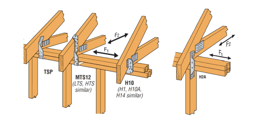
Second, even if the Truss Designer had all of the information regarding the bearing conditions, there is another problem. The Truss Designer has the reactions resulting from the loads applied to the truss. What about the reaction at the top of the wall (perpendicular to the wall) resulting from the lateral loads applied to that wall? And the shear loads acting parallel to the wall as a result of lateral loads applied to the end wall? These loads also need to be resisted by the truss-to-wall connection (hence, the F1 and F2 allowable loads that are published for hurricane ties), so the Truss Designer cannot select an adequate truss-to-wall connection based on the truss reactions alone.
Finally, there’s one more scenario to consider. Say a Building Department requires that truss-to-wall connections must be specified by the Truss Designer on projects that have no Engineer of Record. It wants to ensure trusses are adequately secured to the walls, and the Truss Designer may seem best equipped to determine those connections (this has actually happened in some places). The Truss Designer can find out what exactly the truss is sitting on, and can even calculate some approximate reactions for the top of the wall to conservatively take into account during the selection of the connection. Problem solved? Not entirely. That takes care of the top of the wall, but the load doesn’t stop there. So requiring the Truss Designer to specify the truss-to-wall connection only transfers the problem to the bottom of the wall. Who is going to address those connections?
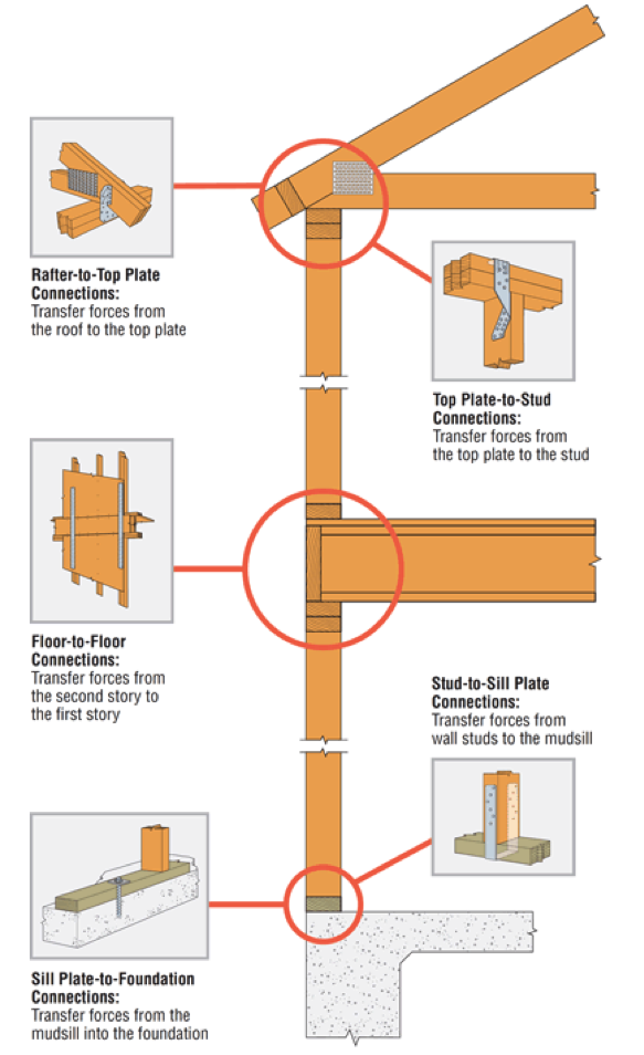
While most people don’t think of the Truss Designer as being the person responsible for the connections at the bottom of the wall, many do think the Truss Designer should be responsible for the connections at the top of the wall. But because someone – namely, the Building Designer – still needs to ensure that a continuous load path has been satisfied by the connections in the building, does it really help to increase the scope of work of the Truss Designer to specify the truss-to-wall connection?
Let us know your thoughts in the comments below.

Fastener Catalog Breakdown: Technical Section LRFD Values
Structures and connections can be designed either using Allowable Strength Design (ASD) method or Load and Resistance Factor Design (LRFD) method. In the ASD method, the allowable strength is calculated by dividing the nominal strength by a safety factor. In the LRFD method, the design strength is calculated by multiplying the nominal strength by the resistance factor. In design, the adjusted ASD design value is compared to a calculated load or stress. As long as the adjusted ASD design value exceeds the calculated load of stress, then the ASD design value is judged safe. In LRFD design, the nominal strength is equated to factored loads. If the factored strength is greater than the factored loads, then the design can be accepted. ASD is the more common method adopted in the professional world.Continue Reading
Our Latest Online Resource: Steel Deck Diaphragm Calculator
Although Simpson Strong-Tie is best known for our structural products: engineered structural connectors, lateral systems, fasteners and fastening systems, anchoring products and most recently, concrete repair, protection and strengthening (RPS) systems, we are continually developing new and exciting software solutions. As we’ve discussed in prior blog posts, Simpson Strong-Tie has numerous software programs and web and mobile apps available for download or online use at www.strongtie.com/software. Today, I’d like to review our recently launched web app, the Steel Deck Diaphragm Calculator. The calculator is accessible from any web browser and doesn’t require downloading or installing special software.
While the method of designing and specifying a steel deck and its attachment can vary by region, most designers are familiar with the Steel Deck Institute (SDI) and its Diaphragm Design Manual, 3rd Edition (DDM03). DDM03 presents diaphragm shear strength and stiffness equations for various steel deck profiles and commonly used attachment types (welds, power-actuated fasteners, or screws). The calculations can be quite tedious, so the SDI has developed numerous tables using these equations and placed them at the back of DDM03 for easy reference.

Since the tables in DDM03 are based solely on the fasteners and deck profiles included, determining diaphragm capacities utilizing any other proprietary fastener or deck profile fall on the designer or the proprietary product’s manufacturer. Enter Simpson Strong-Tie.
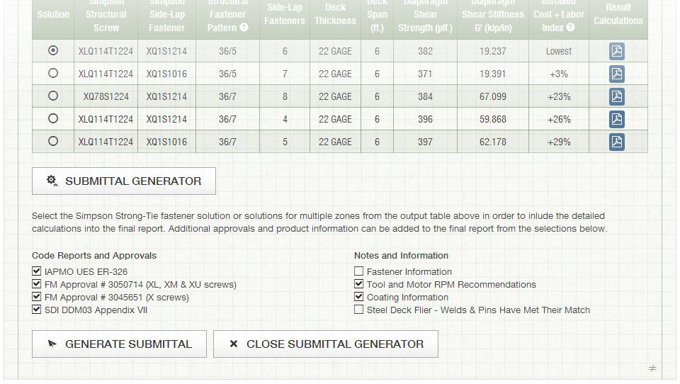
Our Steel Deck Diaphragm Calculator enables users to produce custom diaphragm tables similar to those in DDM03, generate detailed calculations using SDI equations based on project-specific inputs, as well as optimize deck fastening systems to ensure the most cost-effective design is utilized. The calculator incorporates our X-series steel decking screws, including the recently launched Strong-Drive® XL Large-Head Metal Screw, which has one of the highest capacities in the industry and in most cases, can be used as a 1-for-1 replacement of pins or 5/8 diameter puddle welds. (For additional information comparing Simpson Strong-Tie X-series and XL screws to pins or welds, review F-Q- STLDECK14.)

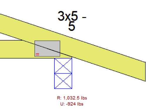
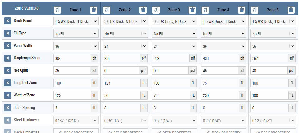
The app can be used with minimal required input to generate tables and project-specific calculations. A more detailed analysis can be performed by inputting parameters for up to five unique zones, including overall dimensions, diaphragm shear, joist spacing, uplift and more.
One unfortunate aspect of many web apps is that your work is typically lost once you close your web browser. I’m happy to report that the folks here in our app development group have added the ability to save and upload project files. The calculator also provides a clean PDF printout of your results while giving you the option to generate a submittal package with supporting documentation, such as code reports, product approvals and installation recommendations.
Try the revised Steel Deck Diaphragm Calculator yourself and let us know what you think. We always appreciate the feedback!
Happy Fourth of July

We wish you a happy and safe Fourth of July from all of us here at Simpson Strong-Tie.
Check back next week for our regular blog posts.
Plated Wood Truss Hip End Styles
For many, the first day of summer means it is time to cinch up your favorite hip-hugging bathing suit and enjoy the warm weather. For the truss industry, it’s time to keep those hip-hugging bathing suits in the closet and take advantage of the favorable weather months by bidding and building as many jobs as possible. During the bid and build frenzy, there will be several hip end jobs leaving truss yards across the country, but what exactly is a hip end and what are the different styles?
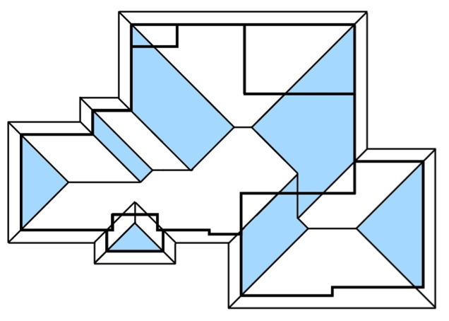
The Structural Building Components Association website (SBCA) defines a hip roof as a “Roof system in which the slope of the roof at the end walls of the building is perpendicular to the slope of the roof along the sides of the building.” While framing terms differ by region, most trussed hip end systems will include hip trusses, jack trusses (end and side) and a rafter or corner girder truss. Hip end style and setback (distance from side or end walls to the hip girder truss) may also vary by building design and region.
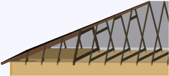
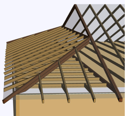
In the western part of the country, a California Hip system is typically seen in many trussed structures. In this hip system, the hip truss flat top chord is dropped by the plumb cut of the jack top chord at the roof pitch. By doing this, the top chords of the end jack trusses can pass over and bear on the dropped flat top chords. As the height of the hip end roof plane increases, the height of the flat top chord also increases, though the interval at which the flat top chord height increases may vary by building design and region.
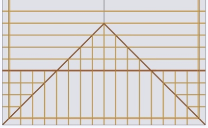
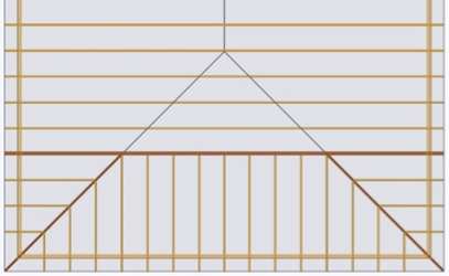
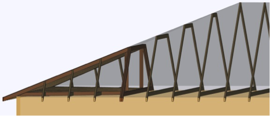
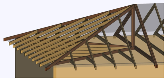
East of the Rocky Mountains, the California Hip is rare and a Step-Down Hip system is more popular. Differing from the California Hip, a Step-Down Hip system is one where every truss under the hip end plane decreases in height, or “steps down” from the apex until it reaches the hip girder, which is placed at a pre-determined setback.
Less regional and more situational depending on the building design, are the Lay-In Gable, Dutch and Terminal Hip systems. The Lay-In Gable Hip system is one with many regional names and shares similarities with the California and Step Hip systems. Like the Step Hip, every truss steps down moving from the apex to the setback. Like the California, every truss flat top chord has a drop. However, the flat top chord is dropped by the plumb cut of a 1.5” member at the roof pitch, as the gable frame lays flat.

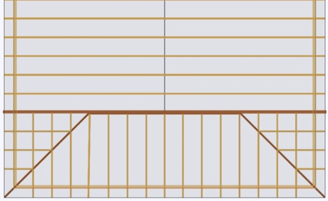
In a Dutch Hip system, the hip end roof plane does not converge with the side planes to form an apex. Instead, the hip end plane pitches directly into the girder truss that is placed at a predetermined setback. Jack trusses then connect to the hip girder truss or to a ledger attached to the hip girder truss. This hip system is also referred to as a Dutch Gable.
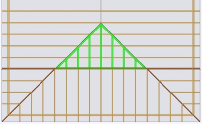
Assuming like roof pitches and heel heights, a Terminal Hip system is one where the hip girder truss setback is half of the main truss span or building width. If pitches and heel heights vary, the girder truss is placed at the apex of the three converging roof planes, which could be more or less than half of the main truss span or building width.

While these are some common hip end styles in the truss industry, there are definitely others. Each style has its own advantages and disadvantages, and a discussion of those will be the topic of a future post.
What other types of hip end styles are you familiar with? Let us know in the comment section below.