Hurricane Strong

This week will see the ultimate combination of events intended to raise public awareness of the necessity for disaster-resistant construction: It is week three of ICC’s Building Safety Month; National Hurricane Preparedness Week, as proclaimed by the U.S. president; the  NOAA Hurricane Awareness Tour of the Gulf Coast; and the kickoff of the new HurricaneStrong program.

hurricanestrong1

The ICC says that “Building Safety Month is a public awareness campaign to help individuals, families and businesses understand what it takes to create safe and sustainable structures. The campaign reinforces the need for adoption of modern, model building codes, a strong and efficient system of code enforcement and a well-trained, professional workforce to maintain the system.” Building Safety Month has a different focus each week for four weeks.  Week One is “Building Solutions for All Ages.”  Week Two is “The Science Behind the Codes.”  Week Three is “Learn from the Past, Build for Tomorrow.” Finally, Week Four is “Building Codes, A Smart Investment.” Simpson Strong-Tie is proud to be a major sponsor of Week Three of Building Safety Month.

hurricanestrong2

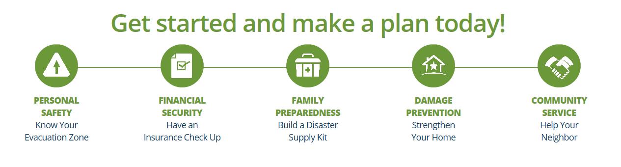
National Hurricane Preparedness Week is recognized each year to raise awareness of the threat posed to Americans by hurricanes. A Presidential Proclamation urged Americans to visit www.Ready.gov and www.Hurricanes.gov/prepare to learn ways to prepare for dangerous hurricanes before they strike. Each day of the week has a different theme. The themes are:
⦁ Determine your risk; develop an evacuation plan
⦁ Secure an insurance check-up; assemble disaster supplies
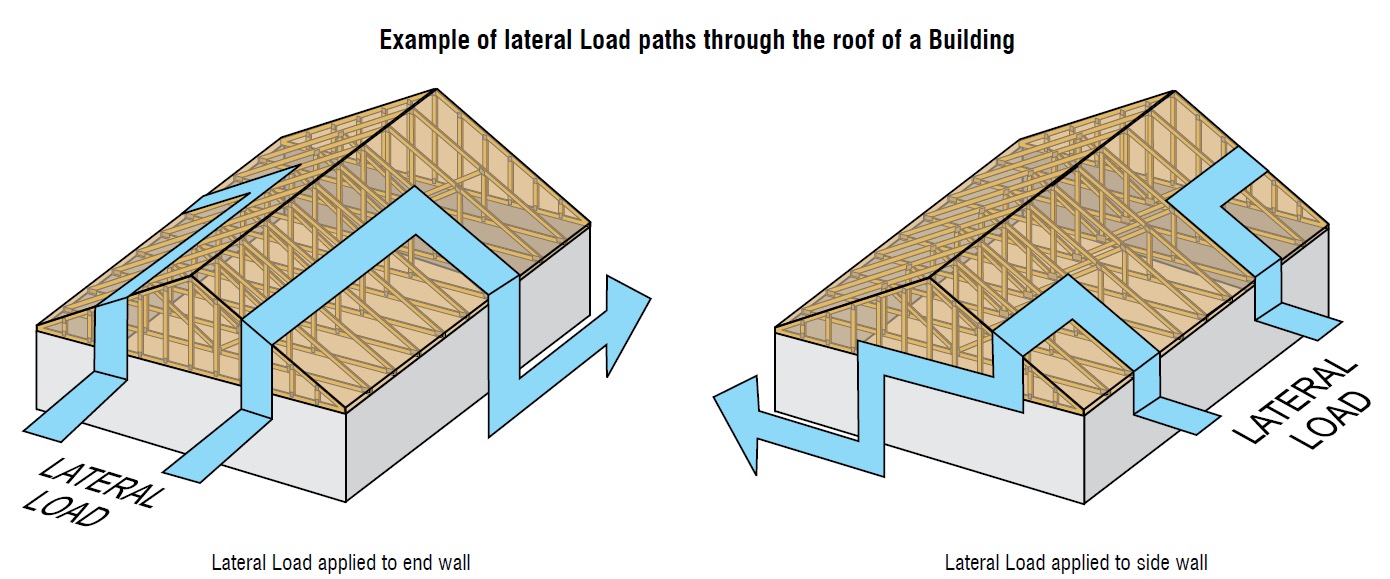
⦁ Strengthen your home
⦁ Identify your trusted sources of information for a hurricane event
⦁ Complete your written hurricane plan.

hurricanestrong3

hurricanestrong4

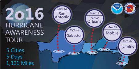
This week also marks the NOAA Hurricane Awareness Tour, where NOAA hurricane experts will fly with two of their hurricane research aircraft to five Gulf Coast Cities. Members of the public are invited to come tour the planes and meet the Hurricane Center staff along with representatives of partner agencies. The goal of the tour is to raise awareness about the importance of preparing for the upcoming hurricane season. The aircraft on the tour are an Air Force WC-130J and a NOAA G-IV. These “hurricane hunters” are flown in and around hurricanes to gather data that aids in forecasting the future of the storm. As with Hurricane Preparedness Week, each day of the tour features a different theme.  Simpson Strong-Tie is pleased to be a sponsor for Thursday, when the theme is Strengthen Your Home.  Representatives from Simpson Strong-Tie will be attending the event on Thursday to help educate homeowners on ways to make their homes safer.

hurricanestrong5

hurricanestrong6

Finally, this week is the official kickoff of a new hurricane resilience initiative, HurricaneStrong. Organized by FLASH, the Federal Alliance for Safe Homes and in partnership with FEMA, NOAA and other partners, the program aims to increase safety and reduce economic losses through collaboration with the most recognized public and private organizations in the disaster safety movement. HurricaneStrong is intended to become an annual effort, with activities starting prior to hurricane season and continuing through the end of the hurricane season on November 30. To learn more, visit www.hurricanestrong.org.


Experts consider these public education efforts to be more important every year, as it becomes longer since landfall of a major hurricane and as more and more people move to coastal areas. The public complacency bred from a lull in major storms has even been given a name: Hurricane Amnesia.


All these efforts may be coming at a good time, assuming one of the hurricane season forecasts is correct. A forecast from North Carolina State predicts an above-average Atlantic Basin hurricane season. On the other hand, forecasters at the Department of Atmospheric Science at Colorado State University are predicting an approximately average year.


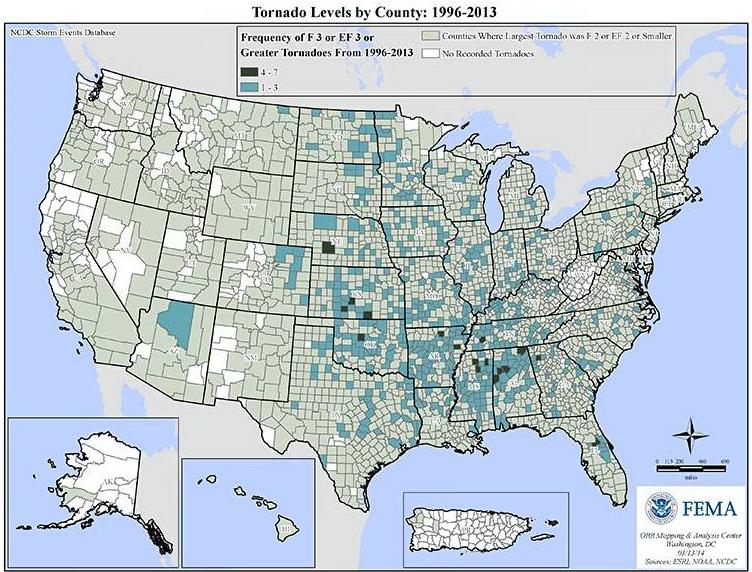
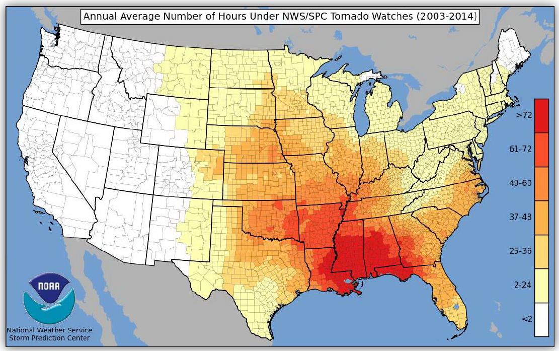
Are you prepared for the natural hazards to which your geographic area is vulnerable? If not, do you know where to get the information you need?


Simpson Strong-Tie® Strong-Wall® Wood Shearwall – The Latest in Our Prefabricated Shearwall Panel Line Part 1

Some contractors and framers have large hands, which can pose a challenge for them when they’re trying to install the holdown nuts used to attach our Strong-Wall® SB (SWSB) Shearwall product to the foundation. Couple that challenge with the fact that anchorage attachment can only be achieved from the edges of the SWSB panel, and variable site-built framing conditions can limit access depending upon the installation sequence. To alleviate anchorage accessibility issues, we’ve required a gap between the existing adjacent framing and SWSB panel equal to the width of a 2x stud to provide access so the holdown nut can be tightened. Even so, try telling a framer an inch and a half is plenty of room in which to install the nut!Continue Reading

Simultaneous Loading on Hurricane Ties

“Structures are connections held together by members” (Hardy Cross)

I heard this quote recently during a presentation at the Midwest Wood Solutions Fair. I had to write it down for future reference because of course, all of us here at Simpson Strong-Tie are pretty passionate about connections. I figured it wouldn’t take too long before I’d find an opportunity to use it. So when I started to write this blog post about the proper selection of a truss-to-wall connection, I knew I had found my opportunity – how fitting this quote is!

There are plenty of photos of damage wrought by past hurricanes to prove that the connection between the roof and the structure is a critical detail. In a previous blog  post, I wrote about whose responsibility it is to specify a truss-to-wall connection (hint: it’s not the truss Designer’s).  This blog post is going to focus on the proper specification of a truss-to-wall connection, the methods for evaluating those connections under combined loading and a little background on those methods (i.e., the fun stuff for engineers).

hurricane1

Take a quick look at a truss design drawing, and you will see a reaction summary that specifies the downward reaction, uplift and a horizontal reaction (if applicable) at each bearing location. Some people are tempted to look only at the uplift reaction, go to a catalog or web app, and find the lowest-cost hurricane tie with a capacity that meets or barely exceeds the uplift reaction.

hurricane2

However, if uplift was the only loading that needed to be resisted by a hurricane tie, why would we publish all those F1 and F2 allowable loads in our catalog?

hurricane3

Of course, many of you know that those F1 and F2 allowable loads are used to resist the lateral loads acting on the end and side walls of the building, which are in addition to the uplift forces.  Therefore, it is not adequate to select a hurricane tie based on uplift reactions alone.

Excerpt from BCSI (2015 Version)

Where does one get the lateral loads parallel and perpendicular to the plate which must be resisted by the truss-to-wall connection? Definitely not from the truss design drawing! Unless otherwise noted, the horizontal reaction on a truss design should not be confused with a lateral reaction due to the wind acting on the walls – it is simply a horizontal reaction due to the wind load (or a drag load) being applied to the truss profile. It is also important to note that any truss-to-wall connection specified on a truss design drawing was most likely selected based on the uplift reaction alone. There may even be a note that says the connection is for “uplift only” and does not consider lateral loads. In this case, unless additional consideration is made for the lateral loads, the use of that connector alone would be inadequate.

Say, for example, that the uplift and lateral/shear load requirements for a truss-to-wall connection are as follows:

Uplift = 795 lb.

Shear (parallel-to-wall) = 185 lb.  (F1)

Lateral (perp-to-wall) = 135 lb.  (F2)
Based on those demand loads, will an H10A work?

hurricane5

An initial look at the H10A’s allowable loads suggests it might be adequate. However, when these loads are entered into the Connector-Selector, no H10A solution is found.

Combined Uplift, F1 and F2 Loads

Why? Because Connector-Selector is evaluating the connector for simultaneous loading in more than one direction using a traditional linear interaction equation approach as specified in our catalog:

hurricane7

If the shear and lateral forces were to be resisted by another means, such that the H10A only had to resist the 795 lb. of uplift, then it would be an adequate connector for the job. For example, the F1 load might be resisted with blocking and RBC clips, and the F2 loads might be resisted with toe-nails that are used to attach the truss to the wall prior to the installation of the H10A connectors. However, if all three loads need to be resisted by the same connector, then the H10A is not adequate according to the linear interaction equation.

Uplift Only
Uplift Only

Some might question how valid this method of evaluation is – Is it necessary? Is it adequate? How do we know? And that is where the interesting information comes in. Several years ago, Simpson Strong-Tie partnered with Clemson University on an experimental study with the following primary objectives:

1. To verify the perceived notion that the capacity of the connector is reduced when loaded in more than one direction and that the linear interaction equation is conservative in acknowledging this combined load effect.

2. To propose an alternative, more efficient method if possible.

Three types of metal connectors were selected for this study – the H2.5A, H10, and the META20 strap – based on their different characteristics and ability to represent general classes of connectors. The connectors were subjected to uni-axial, bi-axial and tri-axial loads and the normalized capacities of the connectors were plotted along with different interaction/design surfaces.

These interaction plots were used to visualize and parameterize the combined load effect on the capacity of the connectors. The three different interaction plots that were examined were the traditional linear relationship, a quadratic interaction surface and a cuboid design space.

Tri-axial Test Frame
Interaction plot for tri-axial loads on a cuboid design space

The results?  Not only was the use of the linear interaction equation justified by this study, but a new, more efficient cuboid design surface was also identified. It provides twice the usable design space of the surface currently used for tri-axial loading and still provides for a safe design (and for the bi-axial case, it is even more conservative than the linear equation). This alternative method is given in our catalog as follows:

hurricane11

Now we can go back to the H10A and re-evaluate it using this alternative method:

hurricane12

As it turns out, the H10A does have adequate capacity to resist the simultaneous uplift, shear and lateral loads in this example. This just goes to show that the alternative method is definitely worth utilizing, whenever possible, especially when a connector fails the linear equation.

For more information about the study, see Evaluation of Three Typical Roof Framing-to-Top Plate/Concrete Simpson Strong-Tie Metal Connectors under Combined Loading.

What is your preferred method for resisting the combined shear, lateral and uplift forces acting on the truss-to-wall connections? Let us know in the comments below!

Impact Community Resilience as a USRC Member and Certified Rater

The U.S. Resiliency Council (USRC) recently launched its Building Rating System for earthquake hazards. The Rating System assigns a score of from one to five stars for three building performance measures: Safety, Damage (repair cost) and Recovery (time to regain basic function).Continue Reading

Shrinkage Compensation Devices

Over the weekend, I had the pleasure of watching my daughter in her cheer competition. I was amazed at all the intricate detail they had to remember and practice. The entire team had to move in sync to create a routine filed with jumps, tumbles, flyers and kicks. This attention to detail reminded me of the new ratcheting take-up device (RTUD) that Simpson Strong-Tie has just developed to accommodate 5/8″ and ¾” diameter rods. The synchronized movement of the internal inserts allows the rod to move smoothly through the device as it ratchets. The new RTUDs are cost effective and allow unlimited movement to mitigate wood shrinkage in a multi-story wood- framed building. When designing such a building, the Designer needs to consider the effect of shrinkage and how to properly mitigate it.

Our SE blog post on Continuous Rod Restraint Systems for Multi-Story Wood Structures explained the importance of load path and  the effects of wood shrinkage. This week’s blog post will focus on the importance of mitigating the shrinkage that typically occurs in multi-story light-frame buildings.

Shrinkage is natural in a wood member. As moisture reaches its equilibrium in a built environment, the volume of a wood member decreases. The decrease in moisture causes a wood-framed building to shrink.

The IBC allows construction of light-framed buildings up to 5 and 6 stories in the United States and Canada respectively. Based on the type of floor framing system, the incremental shrinkage can be up to ¼” or more per floor. In a 5-story building, that can add up to 1-¼” or more and possibly double that when construction settlement is included.

rods1
Typical Example of gap forming between nut and plate when wood shrinkage at top level occurs without shrinkage device.

The Simpson Strong-Tie Wood Shrinkage Calculator is a perfect tool to determine the total shrinkage your building can experience.

Wood Shrinkage Calculator

In order to accommodate the shrinkage that occurs in a multi-story wood-framed building, Simpson Strong-Tie offers several shrinkage compensating devices. These devices have been tested per ICC-ES Acceptance Criteria 316 (AC316) and are listed under ICC-ES ESR-2320 (currently being updated for the new RTUD5, RTUD6, and ATUD9-3).

AC316 limits the rod elongation and device displacement to 0.2 inches between restraints in shearwalls. This deflection limit is to be used in calculating the total lateral drift of a light-framed wood shearwall.

rod3
3 Part Shearwall Drift Equation

The 0.2-inch allowable limit prescribed in AC316 is important to a shearwall’s structural ability to transfer the necessary lateral loads through the structure below to the foundation level. This limit assures that the structural integrity of the nails and sill plates used to transfer the lateral loads through the shearwalls is not compromised during a seismic or wind event. Testing has shown that sill plates can crack when excessive deformation is observed in a shearwalls. Nails have also been observed to pull out during testing.  Additional information on this can be found here.

rod4
Sill Plates Cracked due to excessive uplift at ends of shearwall.
rods5
Nails pull out due to excessive uplift at ends of shearwall.

In AC316, 3 types of devices are listed.

  • Compression-Controlled Shrinkage Compensating Device (CCSCD): This type of device is controlled by compression loading, where the rod passes uninterrupted through the device. Simpson Strong-Tie has several screw-type take-up devices, such as the Aluminum Take-Up Device (ATUD) and the Steel Take-Up Device (TUD), of this type.
rods6
ATUD (CCSCD)
  • Tension-Controlled Shrinkage Compensating Device (TCSCD): This type of device is controlled by tension loading, where the rod is attached or engaged by the device and allows the rod to ratchet through as the wood shrinks. The Simpson Strong-Tie Ratcheting Take-Up Device (RTUD) is of this type.

rod7
RTUD (TCSCD)
  • Tension-controlled Shrinkage Compensating Coupling Device (TCSCCD): This type of device is controlled by tension loading that connects rods or anchors together. The Simpson Strong-Tie Coupling Take-Up Device (CTUD) is of this type.
CTUD (TCSCCD)
CTUD (TCSCCD)

Each device type has unique features that are important in achieving the best performance for different conditions and loads. The following table is a summary of each device.

rods9
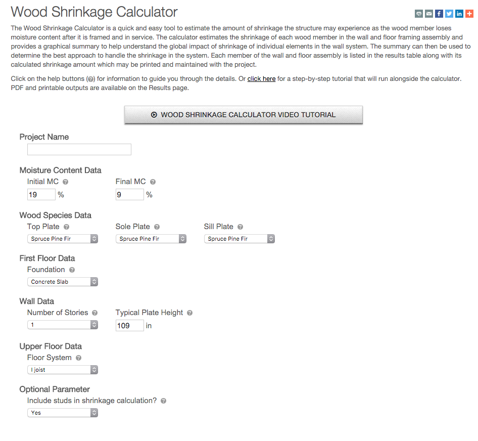
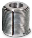
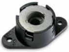
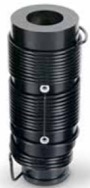
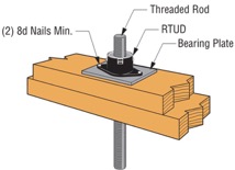
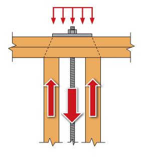
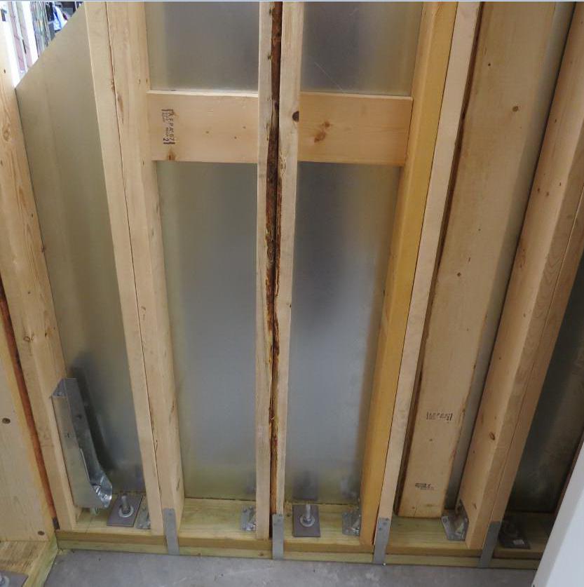
The most cost-effective Simpson Strong-Tie shrinkage compensation device is the RTUD. This device has the smallest number of components and allows the rod unlimited travel through the device. It is ideal at the top level of a rod system run or where small rod diameters are used. Simpson Strong-Tie RTUDs can now accommodate 5/8″ (RTUD5) and ¾” (RTUD6) diameter rods.

How do you choose the best device for your projects? A Designer will have to consider the following during their design.

rod10
RTUD Assembly

Rod Tension (Overturning) Check:

  • Rods at each level designed to meet the cumulative overturning tension force per level
  • Standard and high-strength steel rods designed not to exceed tensile capacity as defined in AISC specification
    • Standard threaded rod based on 36 / 58 ksi (Fy/Fu)
    • High-strength Strong-Rod based on 92 / 120 ksi (Fy/Fu
    • H150 Strong-Rod based on 130 / 150 ksi (Fy/Fu)
  • Rod elongation (see below)

 Bearing Plate Check

  • Bearing plates designed to transfer incremental overturning force per level into the rod
  • Bearing stress on wood member limited in accordance with the NDS to provide proper bearing capacity and limit wood crushing
  • Bearing plate thickness has been sized to limit plate bending in order to provide full bearing on wood member

 Shrinkage Take-Up Device Check

  • Shrinkage take-up device is selected to accommodate estimated wood shrinkage to eliminate gaps in the system load path
  • Load capacity of the take-up device compared with incremental overturning force to ensure that load is transferred into rod
  • Shrinkage compensation device deflection is included in system displacement

 Movement/Deflection Check

  • System deformation is an integral design component impacting the selection of rods, bearing plates and shrinkage take-up devices
  • Rod elongation plus take-up device displacement is limited to a maximum of 0.2″ per level or as further limited by the requirements of the engineer or jurisdiction
  • Total system deformation reported for use in Δa term (total vertical elongation of wall anchorage system per NDS equation) when calculating shearwall deflection
  • Both seating increment (ΔR) and deflection at allowable load (ΔA) are included in the overall system movement. These are listed in the evaluation report ICC-ES ESR-2320 for take-up devices

 Optional Compression Post Design

  • Compression post design can be performed upon request along with the Strong-Rod System
  • Compression post design limited to buckling or bearing perpendicular to grain on wood plate
  • Anchorage design tools are available
  • Anchorage design information conforms to AC 318 anchorage provisions and Simpson Strong-Tie testing

In order to properly design a continuous rod tie-down system for your shearwall overturning restraint, all of the factors listed above will need to be taken into consideration.

A Designer can also contact Simpson Strong-Tie by going to www.strongtie.com/srs and filling out the online “Contact Us” page to have Simpson Strong-Tie design the continuous rod tie-down system for you. This design service does not cost you a dime. A few items will be required from the Designer in order for Simpson Strong-Tie to create a cost-effective rod run (it is recommended that on the Designer specify these in the construction documents):

  • There is a maximum system displacement of 0.2″ per level, which includes rod elongation and shrinkage compensation device deflection. Some jurisdictions may impose a smaller deflection limit.
  • Bearing plates and shrinkage compensation devices are required at every level.
  • Cumulative and incremental forces must be listed at each level in Allowable Stress Design (ASD) force levels.
  • Construction documents must include drawings and calculations proving that design requirements have been met. These drawings and calculations should be submitted to the Designer for review and the Authority Having Jurisdiction for approval.

More information can be obtained from our website at www.strongtie.com/srs, where a new design guide for the U.S., F-L-SRS15, and a new catalog for Canada, C-L-SRSCAN16, are available for download.

rod11
US Design Guide F-L-SRS15 and Canadian Catalog C-L-SRSCAN16

Reminders from Hurricane Katrina

This week is the 10th anniversary of Hurricane Katrina, and we have all seen articles on the lessons learned from the storm. Engineers learn something new from every storm. However, I think that Hurricane Katrina just gave us some very strong reminders of things we already knew.

Hurricane Katrina reminded us that hurricanes are flood events as well as high-wind events. And I don’t mean the flooding in New Orleans. No, I mean the flooding along the Gulf Coast from Louisiana to Florida.

I witnessed the complete devastation of the Mississippi Gulf Coast from Waveland to Biloxi. Structures within the first few (and often many) blocks from the beach were simply flattened by water. Fortunately, these areas are coming back, but the structures being built there now bear little resemblance to the homes that graced the beach 10 years ago.

I remember my father-in-law having his new house built on the coast in Waveland more than 20 years ago. As a young engineer, I gave it the once over and noted that the builder had connected the roof framing to the top plate, but little else. I made some recommendations, such as continuing the connections down throughout the rest of the house to the foundation. The builder followed my suggestions and then presented my father-in-law with the bill “for your son-in-law the inspector.” He was happy to pay it. Nevertheless, although the house was wind resistant, it could not stand up to the rushing waters from Hurricane Katrina.

Katrina reminds us that the only way to get away from floods, other than not building near the water, is to elevate structures above them. Due to flood regulations, new houses along the Gulf Coast are now elevated high in the air, in the hope of avoiding flooding from future storms. Simpson Strong-Tie is proud to have developed some products during the last few years that make it easier to build structures elevated on pilings.

One such product is our CCQM column cap that strengthens the connection of support beams to masonry piers. Another is the Strong-Drive® SDWH Timber-Hex HDG structural screw, which is meant to replace through-bolts to make the connection of a beam to a wood piling easier and more reliable.

CCTQM Installation
CCTQM Installation
Elevated house built with CCQM Column Caps


SDWH TIMBER-HEX HDG Screw

Hurricane Katrina reminds us of the value of building codes. After the storm, the LSU Hurricane Center conducted a number of simulation studies on the effect of a direct, Katrina-like storm on the states of Louisiana, Mississippi and Alabama. The simulations were run on the existing stock of buildings, and then run again on the same stock of buildings, assuming that certain features that result from modern building codes were present. These features included shutters or impact-resistant windows, enhanced nailing of the roof deck to the roof framing, framing connected together with hurricane clips and straps to achieve a continuous load path. In addition, in the Louisiana study, a secondary water barrier over the joints in the roof sheathing was added.

The studies found that the decrease in wind damage from the simulated storms was astounding. In Louisiana, the study showed a 79% reduction in economic losses due to wind. In Alabama, the study revealed a 72% reduction in economic losses due to wind. The Gulf states seem to have received the message loud and clear. In the years following Hurricane Katrina, Louisiana adopted a statewide building code and Mississippi adopted a uniform building code for the four counties along the coast. Recently, Alabama has also adopted a statewide residential and energy code. But in general, building codes are still quite varied in coastal states. This report from the Insurance Institute for Business and Home Safety evaluates the effectiveness of building codes in coastal states.

Finally, Hurricane Katrina reminds those of us who do damage surveys that you need to know what you are getting into before you go. As soon as the storm hit and we saw the scope of the damage, four members of the Simpson Strong-Tie Engineering Department in our McKinney, Texas, office decided we needed to go see the damage first-hand before any repairs were made. So two days after the storm struck, off we went to Jackson, Mississippi. There, we rented two vans stocked up with food, water and fuel. Unfortunately, the fuel and the food/water ended up in separate vans. Before long, we were separated in traffic and could not communicate due to loss of cell signal.

Our team spent two days viewing the damage first-hand along the Louisiana and Mississippi coast, but spent a lot of time our last day trying to find some fuel so we could make it back to Jackson. I remember spending the night in a hotel without power full of storm victims, and then months later receiving the bill and being charged for a movie!

SE Blog 4SE Blog 5

SE Blog 6

What do you remember from Hurricane Katrina? Let us know in the comments below.

Continuous Rod Restraint Systems for Multi-Story Wood Structures

This week was our new employee Sales and Product Orientation class. It reminded me of the post A Little Fun with Testing where we broke a bowling ball. Although breaking stuff is fun, my second favorite part of the class is teaching about the importance of a continuous load path. I think it is really the most important thing a Structural Engineer does. If we don’t pay attention to the loads, where they occur and create a path so they can get where they need to go, a building may not stand up. This week, we also released some new tools and information for our new Strong-Rod™ Systems, which are used to complete the load path for multi-story wood-framed shearwall overturning restraint and roof uplift restraint.

Two Load Paths

All wood-framed buildings need to be designed to resist shearwall overturning and roof-uplift forces. To transfer these tensile forces through the load path, connectors (hurricane ties, straps and holdowns) have been the traditional answer. Simpson Strong-Tie offers a few options there.  With the growth in multi-story wood-framed structures, where the code requires shrinkage to be addressed and overturning and uplift forces are typically higher, rod systems have become an increasingly popular load restraint solution. Our Anchor Tiedown System (ATS) for shearwall overturning restraint has been around for many years. A new Strong-Rod Systems Design Guide and revamped web pages provide information on new design options, components and configurations.

Strong-Rod Systems Seismic and Wind Restraint Systems Guide

The guide and website focus more on the unique design considerations for rod systems, how you should specify the system and highlight the design services that we provide. They also provide more detail and design information for our relatively new Uplift Restraint System (URS) for roofs. Connectors are a common choice for transferring the net roof uplift forces from wind events down the structure. Although in some high-wind areas, rod systems are preferred.

ATS and URS Continuous Rod Tiedown Systems

I’ll touch on some of the design considerations for these types of systems below, but back to the load path. For shearwall overturning restraint using holdowns, the load path is fairly simple. Once the lateral load is in the shearwall, the sheathing and nailing lifts up on the post. The holdown connects to the post, holding it down and transferring the forces to the foundation or level below. A continuous rod tiedown system follows a little different path. The sheathing and nailing lifts up on the boundary posts and the posts push up on the framing above until the load is resisted in bearing by a bearing plate. The load is then transferred into the rod and down to the foundation. There has been a lot of testing and research on the effects of skipping restraint locations where a bearing plate restraint is installed at every other floor or only at the top level.  Doing that will change the load path because the load has to continue to travel up until a restraint holds it down. It also negatively impacts the stiffness and drift of the shearwall stack, not to mention increases project cost because the boundary posts, rod and bearing must be sized to transfer the cumulative overturning forces from each level.

ATS load path
ATS load path

Wood Shrinkage, Take-up Devices and Displacement Limits

Shrinkage is not just a Seinfeld episode cult classic. It is also something that designers need to consider when designing wood structures. IBC Section 2304.3.3 requires that designers evaluate the impact of wood shrinkage on the building structure when bearing walls support more than two floors and a roof. The effects of wood shrinkage can impact many things in the structure from finishes to MEP systems to the continuous rod system. As the wood members lose moisture, the wood shrinks and the building settles. This can cause gaps at the bearing plate locations of continuous rod systems because the continuous steel rod doesn’t shrink. That is where the magic of take-up devices comes in. They allow the building to shrink but keep gaps from forming by filling the gap (expanding devices – can be screw style or ratcheting), ratcheting down the rod (ratcheting devices), or making the rod shrink as much as the wood (contracting coupling device).


In addition to keeping the rod system tight to insure the intended performance, it is important to consider the movement associated with the rod system when under wind or earthquake loading. The IBC requires shearwall displacements to be within story drift limits in moderate to high seismic regions. We highlighted some of the changes coming for the evaluation of shearwall deflection in the previous post discussing the New Treatment of Shear Wall Aspect Ratios in the 2015 SDPWS. For continuous rod systems, there are some additional limits. ICC-ES AC316 Acceptance Criteria for Shrinkage Compensating Devices requires designs to limit displacement between restraints to 0.20 inches (including rod elongation and device displacement) for shearwall restraint. The movement of the take-up device plays a big part in meeting this requirement and the rod diameter required. Screw-style devices have the lowest total movement. Ratcheting devices are appropriate in many cases as well such as the upper levels where loads are lower, but may require larger rod diameters to meet the displacement limit.

figure5ICC-ES AC391 Acceptance Criteria for Continuous Rod Tie-down Runs and Continuous Rod Tie-down Systems Used to Resist Wind Uplift covers continuous rod systems for roof uplift restraint. The displacement limit for the Continuous Rod Tie-down Run (just the rod system components) is limited to 0.18 inches of rod elongation for the total length of rod. The Strong-Rod URS evaluates the Continuous Rod Tie-down System (the whole load path). Displacement limits for the system are L/240 for the top plate bending and 0.25 inches total deflection at the top plate between tie-down runs (including top plate bending, rod elongation, wood bearing deformation and take-up device displacement). The differences between the rod run and rod system analysis as well as other design considerations are explained in more detail in the design guide and on our website.

I always end my continuous load path presentation during orientation class with the same questions and if they were paying attention I get the response I want.

“What is the most important thing a Structural Engineer does?”

“Designs a continuous load path for the building!”

“What does Simpson Strong-Tie do?”

“Provides product and system solutions to help  engineers do their job!”

Take a look at the new Strong-Rod Systems tools and information and let us know how we can help you with your next multi-story wood-framed project.

What related blog topics would you like to discuss? Let us know in the comments below.

Which Tornado Saferoom is Right for You?

tornado1
Image courtesy of FLASH.

There certainly seems to be increased awareness of the potential for damage and injury from tornadoes these days. Recent information published by the Federal Emergency Management Agency (FEMA) and the Federal Alliance for Safe Homes (FLASH) help explain that. This increased awareness has led to a growing interest in tornado shelters for protection of life and property.

This FEMA graphic shows that most areas of the United States have been affected by a tornado at some point since 1996, and many have been affected by one or more strong tornadoes (EF3 or greater).

Figure 1 - Tornado activity by county: 1996-2013
Figure 1 – Tornado activity by county: 1996-2013

Living in North Texas near the Simpson Strong-Tie manufacturing plant in McKinney, Texas, I know all too well the sinking feeling of hearing the tornado sirens and turning on the TV to find you are under a tornado watch. FLASH recently published a graphic developed by the National Weather Service that shows the large number of U.S. counties that have been under a tornado watch between 2003-2014, and the high number of warnings that some counties experienced.

Figure 2 -  Annual average number of hours under NWS/SPC tornado watches (2003-2014)
Figure 2 – Annual average number of hours under NWS/SPC tornado watches (2003-2014)

Other than moving to an area that has fewer tornadoes, one of the best ways to protect your family and at least have more peace of mind during tornado season is to have a tornado shelter or safe room. These structures are designed and tested to resist the highest winds that meteorologists and engineers believe occur at ground level during a tornado and the debris that is contained in tornado winds.

Tornado shelters can be either pre-fabricated and installed by a specialty shelter manufacturer, or can be site-built from a designed plan or pre-engineered plan. A good source for information on pre-fabricated shelters is the National Storm Shelter Association, a self-policing organization that has strict requirements for the design, testing and installation of its members’ shelters.

FEMA publishes a document, P-320, Taking Shelter from the Storm, that provides good information on safe rooms in general, as well as several pre-engineered plans for tornado safe rooms.

To highlight the different types of safe rooms covered by FEMA P-320, FEMA, FLASH and the Portland Cement Association (PCA) sponsored an exhibit at January’s International Builder’s Show. The exhibit was called the “Home Safe Home Tornado Saferoom Showcase.” It featured six different types of saferooms that builders could incorporate into the homes they build. Simpson Strong-Tie and the American Wood Council collaborated to build a wood frame with steel sheathing safe room meeting the FEMA P-320 plans. Other safe rooms shown at the exhibit included pre-cast concrete and pre-manufactured steel shelters manufactured by NSSA members, and reinforced CMU, ICF cast-in-place concrete and aluminum formed cast-in-place concrete built to FEMA P-320 plans.

Figure 4 - Home Safe Home Tornado Saferoom Showcase
Figure 4 – Home Safe Home Tornado Saferoom Showcase

Simpson Strong-Tie staff in McKinney, Texas, constructed the wood frame/steel sheathing safe room in panels and shipped it to the show. It was built from locally sourced lumber, readily available fasteners and connectors and sheets of 16 ga. steel (which we happen to keep here at the factory). It had cut-away sheathing at the corners to show the three layers of sheathing needed. Our message to builders was that this type of shelter would be the easiest for their framers to build on their sites.

tornado5
Figure 5: Holdowns and plate anchorage
tornado6
Figure 6: Roof-to-wall connections
tornado7
Figure 7: A visitor examines our tested door, a vital component of any shelter. This one was furnished by CECO Doors.

The sponsors of the exhibit took advantage of the variety of safe rooms in one place to film a video series, “Which Tornado Safe Room is Right for You?The videos are posted at the FLASH StrongHomes channel on YouTube. The series provides comparative information on cast-in-place, concrete block masonry, insulated concrete forms, precast concrete and wood-frame safe rooms, with the goal of helping consumers to better understand their tornado safe room options.

“Today’s marketplace offers an unprecedented range of high-performing, affordable options to save lives and preserve peace of mind for the millions of families in the path of severe weather,” said FLASH President and CEO Leslie Chapman-Henderson. “These videos will help families understand their options for a properly built safe room that will deliver life safety when it counts.”

FLASH released the videos earlier this month as part America’s PrepareAthon!, a grassroots campaign to increase community emergency preparedness and resilience through hazard-specific drills, group discussions and exercises. The overall goal of the program is to get individuals to understand which disasters could happen in their community, know what to do to be safe and mitigate damage from those disasters, take action to increase their preparedness, and go one step farther by participating in resilience planning for their community. Currently, the program focuses on preparing for the disasters of tornadoes, hurricanes, floods, wildfires, earthquakes and winter storms.

Do you know what the risk of disasters is in your community? If you are subject to tornado risk, would you like to build your own safe room, have one built to pre-engineered plans or buy one from a reputable manufacturer? Let us know in the comments below.

Changes to 2012 IBC for Wind Design

The Greek philosopher Heraclitusis credited with saying “The only thing that is constant is change.”

If that applies to building codes, then it applies doubly to wind design using the 2012 International Building Code® (IBC).

The wind load requirements in Section 1609 of the IBC are based on ASCE 7 and refer to this document for most design information. In the 2012 IBC, the referenced version of ASCE 7 changed from the 2005 edition to the 2010 edition. In ASCE 7-10, the wind design requirements have been completely revised, including a complete design philosophy change.

SE blog 1

Wind design has changed from an allowable strength-based philosophy with a load factor of 1 in the ASD load combination to an ultimate strength design philosophy with a load factor of 1 in the strength design load combination. This means wind design has a similar basis as seismic design. So the new load combinations for wind look like this:

Strength Design: 0.9D + 1.0W
Allowable Stress Design: 0.6D + 0.6W

Because of the change in load factor and philosophy, the basic wind speed map had to be altered. In the past, one map was provided and the design return period was increased for certain occupancies by multiplying the load by an importance factor. In ASCE 7-10 there are three maps provided so now an importance factor is no longer needed. The return period of the map depends on the risk to human life, health and welfare that would result from the failure of that type of building. This was previously called the Occupancy Category, but it is now called the Risk Category.

Risk Category III and IV buildings use a basic wind speed map based on a 1,700-year return period. Risk Category II buildings use a basic wind speed map based on a 700-year return period. And Risk Category I buildings use a basic wind speed map based on a 300-year return period. Because of the higher return period, the mapped design wind speed will be much higher than when using previous maps. However, with the lower load factors, actual design loads will be the same or in many areas lower due to other changes in the way the map was developed.

wind map
Excerpted from the 2015 International Residential Code; Copyright 2014. Washington D.C.: International Code Council. Reproduced with permission. All rights reserved. www.iccsafe.org

SE blog 3

Another change to ASCE 7-10 for wind design is that Exposure D is no longer excluded from hurricane prone regions; so buildings exposed to large bodies of water in hurricane prone regions will have to be designed for Exposure D.

Because of the change in wind speeds, there is a change in the definitions of windborne debris regions. Due to the different wind speed design maps, the windborne debris region will be different depending on the Risk Category of the building being built. The windborne debris region is now defined as areas within hurricane-prone regions that are either within 1 mile of the coastal mean high water line where the ultimate design wind speed is 130 mph or greater; or any areas where the ultimate design wind speed is 140 mph or greater; or Hawaii. Risk Category II buildings and structures and Risk Category III buildings and structures (except health care facilities), use the 700-year Risk Category II map to define wind speeds for the purpose of determining windborne debris regions. Risk Category IV buildings and structures and Risk Category III health care facilities use the 1700-year return Category III/IV wind speed map to define wind speeds for the purpose of determining windborne debris regions.

Finally, a new simplified method for determining wind loading on ENCLOSED SIMPLE DIAPHRAGM BUILDINGS WITH h ≤ 160 ft has been added to ASCE 7-10. This is different from the simplified all heights method in the IBC, so it will be interesting to see which method becomes more widely used. Which method do you prefer? Let us know in the comments below.

Educated in a FLASH, Part 2

This week’s blog was written by Branch Engineer Randy Shackelford, P.E., who has been an engineer for the Simpson Strong-Tie Southeast Region since 1994. He is an active member of several influential committees, including the AISI Committee on Framing Standards, the American Wood Council Wood Design Standards Committee, and the Federal Alliance for Safe Homes Technical Advisory Committee. He is vice-president and member of the Board of Directors of the National Storm Shelter Association. Randy has been a guest speaker at numerous outside seminars and workshops as a connector and high wind expert. Here is Randy’s post:

In my last blog post, I gave an overview of FLASH, the Federal Alliance for Safe Homes, and how Simpson Strong-Tie partners with them. Last November, FLASH held their Annual Conference.  The theme of this past meeting was “15 Years of Stronger Homes and Safer Families,” and it was one of their best conferences yet.Continue Reading