Holdown Anchorage Solutions

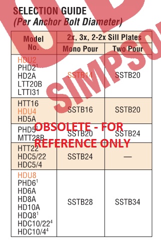
A common question we get from specifiers is “What anchor do I use with each holdown?” Prior to the adoption of ACI 318 Appendix D, this was somewhat simple to do. We had a very small table near the holdown section of our catalog that listed which SSTB anchor worked with each holdown.

The good old days! (Don’t use this today.)

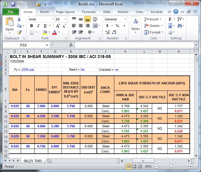
During the good old days, anchor bolts had one capacity and concrete wasn’t cracked. ACI 318 Appendix D gives us reduced capacities in many situations, different design loads for seismic or wind and reductions for cracked concrete. These changes have combined to make anchor bolt design more challenging than it was under the 1997 Uniform Building Code.

This blog has had several posts related to holdowns. So, What’s Behind a Structural Connector’s Allowable Load? (Holdown Edition) explained how holdowns are tested and load rated in accordance with ICC-ES Acceptance Criteria. Damon Ho did a post, Use of Holdowns During Shearwall Assembly, which discussed the performance differences of shearwalls with and without holdowns, and Shane Vilasineekul did a Wood Shearwall Design Example. So I won’t get in to how to pick a holdown.

Once you have determined your uplift requirements and selected a post size and holdown, it is necessary to provide an anchor to the foundation. To help Designers select an anchor that works for a given holdown, we have created different tables that provide anchorage solutions for Simpson Strong-Tie holdowns.

SSTB Anchor Bolt
SSTB Anchor Bolt
SB Anchor Bolt
SB Anchor Bolt

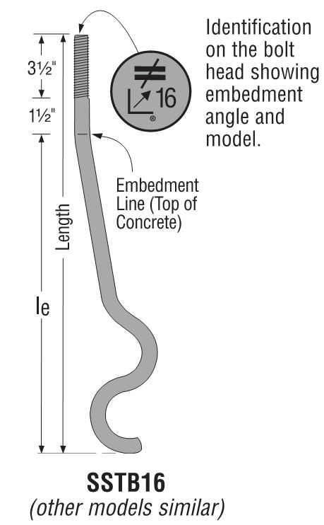
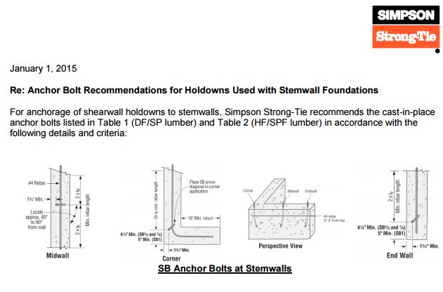
There is one Engineering letter that addresses slab-on-grade foundations and another version that covers stemwall foundations. The tables are separated by wood species (DF/SP and SPF/HF) to give the most economical anchor design for each post material. The preferred anchor solutions are SSTB or SB anchors, as these proprietary anchor bolts are tested and will require the least amount of concrete. When SSTB or SB anchors do not have adequate capacity, we have tabulated solutions for the PAB anchors, which are pre-assembled anchors that are calculated in accordance with ACI 318 Appendix D.

Slab On Grade Anchorage Solutions
Stemwall Anchorage Solutions

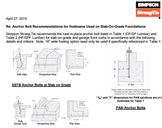
The solutions in the letters are designed to match the capacity of the holdowns, which allows the contractor to select an anchor bolt if the engineer doesn’t specify one. They are primarily used by engineers who don’t want to design an anchor or select one from our catalog tables. We received some feedback from customers who were frustrated that some of our heavier holdowns required such a large footing for the PAB anchors, whereas a slightly smaller holdown worked with an SB or SSTB anchor in a standard 12″ footing with a 1½” pop out.

6-in Popout FEA Model
6-in Popout Physical Testing

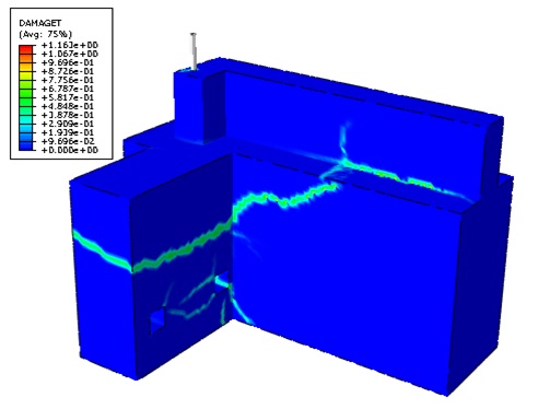
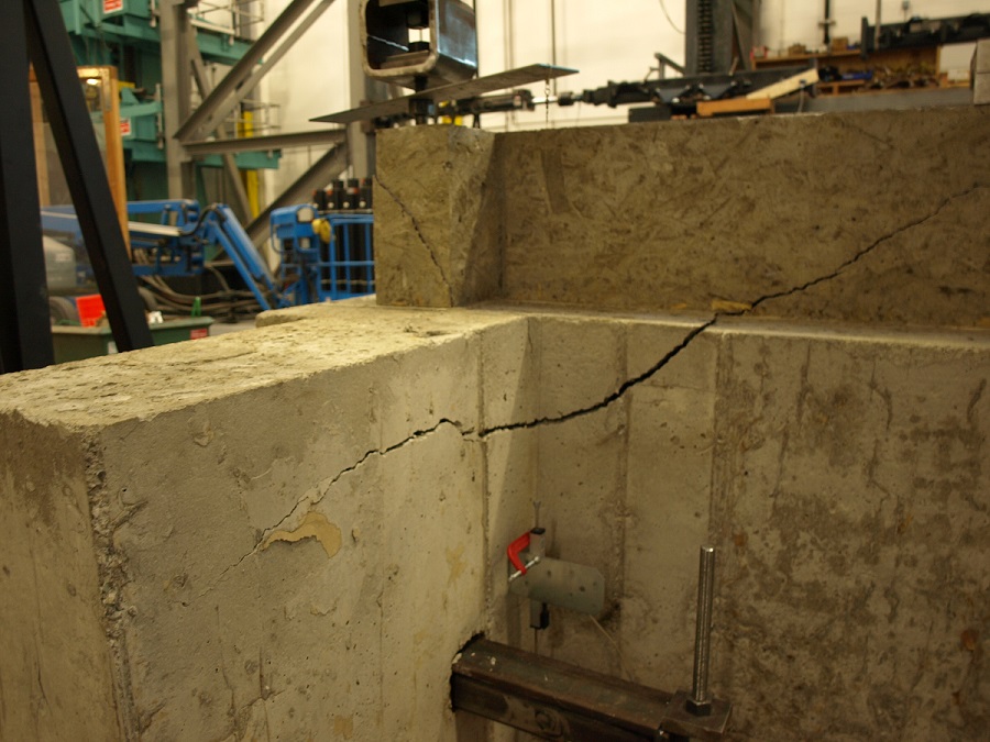
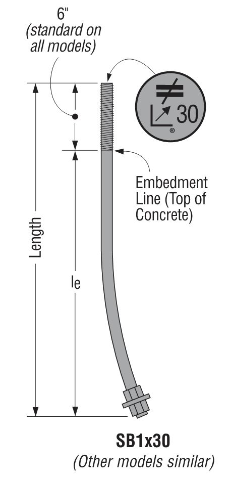
To achieve smaller footings using our SB1x30 anchor bolts, we reviewed our original testing and created finite element (FEA) models to determine what modifications to the slab-on-grade foundation details would meet our target loads. Of course, we ran physical tests to confirm the FEA models. With a 6″ pop out, we were able to achieve design loads for HD12, HDU14 and HHDQ14.

HD12, HDU14 & HHDQ14 Solutions
HD12, HDU14 and HHDQ14 Solutions

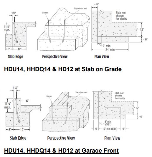
The revised footing solutions for the heavier holdowns require less excavation and less concrete than the previous Appendix D calculated solutions, reducing costs on the installation.

What has been your experience with holdown anchorage? Tell us in the comments below.

New Simpson Strong-Tie Anchor Designer software

Remember back to the days when you used allowable stress design for designing anchorage to concrete? Once you had your design loads, selecting an anchor was quick and easy. The 1997 UBC covered the anchorage to concrete in less than two pages, so the calculation was painless. Post-installed anchors were even easier, since allowable loads were tabulated and you just needed to apply a couple of edge distance and spacing reductions.

Since the introduction of strength design provisions and the adoption of ACI 318 Appendix D, first in the 2000 IBC, designing code-compliant anchorage to concrete has become much more complex. At least once (and probably not more) armed with a pencil,  calculator, and an eraser, most of us have set out to design a ‘simple’ anchorage to concrete connection using the  Appendix D provisions. Several pages of calculations later (and hopefully with a solution to the problem), most of us, I imagine, came to realize that designing anchorages to concrete by hand required much more time and effort than we anticipated or could allocate time for. As a result, many of us probably created an Excel template to speed up the design process using built-in functions and some Visual Basic programming.

I'm never going for looks on my spreadsheets.
I’m never going for looks on my spreadsheets.

The question is: are you still using the template?

For me, the answer is an emphatic “NO”, mainly because the spreadsheet I created has limited capability given the complexity in adapting the design methodology to complex anchor layouts, changes to the design provisions with each new code edition, and the need to add/modify data each time a new post-installed anchor product is introduced.

Continue Reading

The Anchorage to Concrete Challenge – How Do You Meet It?

We structural engineers here at Simpson Strong-Tie have a love/hate relationship with anchorage to concrete. Ever since the introduction of the strength design provisions in the 2000 IBC and ACI 318 Appendix D, anchorage to concrete has been a challenge for designers, building officials and manufacturers. SEAONC’s recent testing and the resulting code changes offer some relief to wood-frame designers for sill-plate anchor design at the edge of concrete, but many challenges remain.

Concrete Breakout in a Shallow Slab

With the increasing demand for high-density housing and urban infill projects, designers are now faced with anchoring multi-story wood-framed shear walls to relatively thin elevated concrete slabs (typically referred to as podium slabs).  Overturning tension anchorage forces at the ends of shear walls in these projects can routinely be in the 40 kip range and even get as high as 60 kips or more.

Continue Reading