Applying ACI 318-14 Development Length Provisions to Post-Installed Reinforcing Bars Secured to Concrete with Construction Adhesive

The evaluation report, ESR-4057, was recently updated to allow the design of SET-3G adhesive for post-installed reinforcing bars using the ACI 318 development length provision. This blog has been reposted replacing SET-XP with SET-3G using the original design examples. The SET-XP evaluation report, ESR-2508, currently limits f’c to 2,500 psi for seismic applications located in seismic design category C–F. SET-3G does not carry the same limitation allowing for a considerable reduction in development length at higher values of f’c. In general, a substantially lower installation cost can be expected using SET-3G for seismic applications. Additionally, SET-3G has slightly reduced edge and spacing requirements. Engineers can access a free online calculation tool to easily determine the rebar development or lap splice length for either adhesive product.

I first learned about the application of the ACI 318 development length provision to post-installed reinforcing bars back in 2003 when I read Post-Installed Adhesive-Bonded Splices in Bridge Decks, authored by Ronald A. Cook and Scott D. Beesheim. In their series of experiments, holes were drilled adjacent to cast-in-place bars using a carbide-tipped drill bit, and new bars were secured in these holes using an anchoring adhesive presumed to be of a type commonly used in concrete construction.
Continue Reading

Are You Ready to Design Post-Installed Anchors in Cracked Masonry?

Design criteria for cracked-concrete masonry units are finally available for adhesive anchors.

It has been over 15 years since cracked concrete changed the way anchorage to concrete was qualified and designed. The ICC International Building Code (IBC) 2003 referenced American Concrete Institute (ACI) 318-02 Appendix D as a design provision for both cast-in-place and post-installed anchors into concrete. Appendix D was the first introduction of cracked concrete to designers. These design provisions required mechanical anchors to be qualified per ACI 355.2, which mandated testing  of anchors in cracks. The Masonry Society (TMS) 405 has not addressed cracks in concrete masonry units since the code’s introduction to concrete in 2003. The Concrete and Masonry Anchor Manufacturers Association (CAMA) has taken on the task of introducing cracked masonry unit testing, qualification and design by updating Acceptance Criteria AC58. These criteria were developed to address the testing and qualification of adhesive anchors in grouted, hollow, and partially grouted concrete masonry units, as well as in brick masonry units.

Continue Reading

Simpson Strong-Tie® SET-3G™ Adhesive Offers a Ductile Solution for Post-Installed Anchorage near a Concrete Edge

Designing post-installed anchorage near a concrete edge is challenging, especially since the ACI provisions for cracked-concrete anchorage went into effect. In the following post, one of our field engineers, Jason Oakley, P.E., explains how SET-3G™ and Anchor Designer™ software from Simpson Strong-Tie make it easier to design a ductile anchor solution.

Engineers often provide holdown anchoring solutions near a concrete edge to help prevent overturning of light-frame shear walls during a seismic (or high-wind) event. Sometimes a post-installed anchor must be used if the cast-in-place anchor was mislocated or misinstalled, or is located where a retrofit or addition is needed. Since the cracked-concrete anchorage design provisions went into effect more than a decade ago, it has been challenging for engineers to offer a near-edge post-installed anchoring solution. This is especially true for structures subject to earthquake loads in seismic design category (SDC) C through F. Simpson Strong-Tie’s new SET-3G epoxy is the first anchoring adhesive in the industry to offer exceptionally high bond-strength values that permit ductile anchorage in concrete near an edge. This blog post will cover a specific example that focuses on Chapter 17 of ACI 318-14 to design a threaded rod, anchored with SET-3G adhesive, used to secure a holdown located 1 3/4″ away from a single concrete edge (Figure 1).
Continue Reading

New CSS Product Launch — FRCM Strengthening Products

The new FRCM Composite Strengthening Systems™ repair and reinforcement solution from Simpson Strong-Tie combines high-performance sprayable mortar with a carbon-fiber grid that creates a thin structural layer that repairs and strengthens without significantly increasing the structure’s weight or volume. FRCM stands for fabric-reinforced cementitious matrix. Its advantages are similar to those of FRP (that is, strength, low weight and ease of application), but it may also be used to repair, resurface, strengthen and protect in one application, along with providing greater resistance to heat and better long-term durability.
Continue Reading

What Structural Engineers Need to Know About the New OSHA Silica Dust Standards

In March of 2016, the United States Department of Labor issued new OSHA standards on how crystalline silica dust should be handled in various workplaces including within the construction industry. The changes are intended to limit workers’ exposure to and inhalation of silica dust on the jobsite. These regulations will replace the current standard, which was issued in 1971. Compliance with the new rules will be required on construction jobsites starting September 23, 2017, and will be enforced through OSHA from that time forward.
Continue Reading

Top 10 Changes to Structural Requirements in the 2018 IBC

This blog post will continue our series on the final results of the 2016 ICC Group B Code Change Hearings, and will focus on 10 major approved changes, of a structural nature, to the International Building Code (IBC).

  1. Adoption of ASCE 7-16
    • The IBC wind speed maps and seismic design maps have been updated.
    • A new section has been added to Chapter 16 to address tsunami loads.
    • Table 1607.1 has been revised to change the deck and balcony Live Loads to 1.5 times that of the occupancy served.
  2. New and Updated Reference Standards
    • 2015 IBC Standard ACI 530/ASCE 5/TMS 402-13 will be TMS402-16.
    • ACI 530.1/ASCE 6/TMS 602-13 will be TMS 602-16.
    • AISC 341-10 and 360-10 have both been updated to 2016 editions.
    • AISI S100-12 was updated to the 2016 edition.
    • AISI S220-11 and S230-07 were updated to the 2015 edition.
    • AISI S200, S210, S211, S212 and S214 have been combined into a new single standard, AISI S240-15.
    • AISI S213 was split into the new S240 and AISI S400-15.
    • ASCE 41-13 was updated to the 2017 edition.
    • The ICC 300 and ICC 400 were both updated from 2012 editions to 2017 editions.
    • ANSI/NC1.0-10 and ANSI/RD1.0-10 were all updated to 2017 editions.
  3. Section 1607.14.2 Added for Structural Stability of Fire Walls
    • This new section takes the 5 psf from NFPA 221, so designers will have consistent guidance on how to design fire walls for stability without having to buy another standard.
  4. Modifications of the IBC Special Inspections Approved
    • Section 1704.2.5 on special inspection of fabricated items has been clarified and streamlined.
    • The Exception to 1705.1.1 on special inspection of wood shear walls, shear panels and diaphragms was clarified to say that special inspections are not required when the specified spacing of fasteners at panel edges is more than 4 inches on center.
    • The special inspection requirements for structural steel seismic force-resisting systems and structural steel elements in seismic force-resisting systems were clarified by adding exceptions so that systems or elements not designed in accordance with AISC 341 would not have to be inspected using the requirements of that standard.
  5. Changes Pertaining to Storm Shelters
    • A new Section 1604.11 states that “Loads and load combinations on storm shelters shall be determined in accordance with ICC 500.”
    • An exception was added stating that when a storm shelter is added to a building, “the risk category for the normal occupancy of the building shall apply unless the storm shelter is a designated emergency shelter in accordance with Table 1604.5.”
    • Further clarification in Table 1604.5 states that the type of shelters designated as risk category IV are “Designated emergency shelters including earthquake or community storm shelters for use during and immediately after an event.”
  6. Changes to the IBC Conventional Construction Requirements in Chapter 23
    • The section on anchorage of foundation plates and sills to concrete or masonry foundations reorganized the requirements by Seismic Design Category (SDC) and added a new section on anchoring in SDC E. It also states that the anchor bolt must be in the middle third of the width of the plate and adds language to the sections on higher SDCs saying that if alternate anchor straps are used, they need to be spaced to provide equivalent anchorage to the specified 1/2″- or 5/8″-diameter bolts.
    • The second change permits single-member 2-by headers, to allow more space for insulation in a wall. 
  7. Modification to the Requirements for Nails and Staples in the IBC
    • ASTM F1667 Supplement One was adopted that specifies the method for testing nails for bending-yield strength and identifies a required minimum average bending moment for staples used for framing and sheathing connections.
    • Stainless-steel nails are required to meet ASTM F1667 and use Type 302, 304, 305 or 316 stainless steel, as necessary to achieve the corrosion resistance assumed in the code.
    • Staples used with preservative-treated wood or fire-retardant-treated wood are required to be stainless steel.
    • The new RSRS-01 nail was incorporated into TABLE 2304.10.1, the Fastening Schedule. The RSRS nail is a new roof sheathing ring shank nail designed to achieve higher withdrawal resistances, in order to meet the new higher component and cladding uplift forces of ASCE 7-16.
  8. Truss-Related Code Change
    • The information required on the truss design drawings was changed from “Metal connector plate type” to “Joint connection type” in recognition that not all trusses use metal connector plates.
  9. Code Change to Section 2304.12.2.2
    • A code change clarifies in which cases posts or columns will not be required to consist of naturally durable or preservative-treated wood. This change makes the requirements closer to the earlier ones, while maintaining consistency with the subsequent section on supporting members.
    • If a post or column is not naturally durable or preservative-treated, it will have to be supported by concrete piers or metal pedestals projecting at least 1″ above the slab or deck, such as Simpson Strong-Tie post bases that have a one-inch standoff.
  10. Code Change to IBC Appendix M
    • A code change from FEMA makes IBC Appendix M specific to refuge structures for vertical evacuation from tsunami, and the tsunami hazard mapping and structural design guidelines of ASCE 7-16 would be used rather than those in FEMA P-646.

Once the 2018 IBC is published in the fall, interested parties will have only a few months to develop code changes that will result in the 2021 I-Codes. Similar to this last cycle, code changes will be divided into two groups, Group A and Group B, and Group A code changes are due January 8, 2018. The schedule for the next cycle is already posted here.

What changes would you like to see for the 2021 codes?

What’s New in the ACI 440.2R-17?

The wait is over. The ACI 440.2R-17 Guide for the Design and Construction of Externally Bonded FRP Systems for Strengthening Concrete Structures is now available. The following post will highlight some of the major changes represented by this version of the document.

It’s been a long road and countless committee hours to get from the last version of ACI 440.2R-08 to this document. While there are multiple smaller changes throughout the document, the most notable update is the addition of Chapter 13 – Seismic Strengthening.


The new seismic chapter addresses the following FRP strengthening scenarios:

  • Section 13.3 – Confinement with FRP
    • This section includes all of the following: general considerations; plastic hinge region confinement; lap splice clamping; preventative buckling of flexural steel bars.
  • Section 13.4 – Flexural Strengthening
    • The flexural capacity of reinforced concrete beams and columns in expected plastic hinge regions can be enhanced using FRP only in cases where strengthening will transfer inelastic deformations from the strengthened region to other locations in the member or the structure that are able to handle the ensuing ductility demands.
  • Section 13.5 – Shear Strengthening
    • To enhance the seismic behavior of concrete members, FRP can be used to prevent brittle failures and promote the development of plastic hinges.
  • Section 13.6 – Beam-Column Joints
    • This section covers a great deal of recent research on the design and reinforcement of beam-column joints.
  • Section 13.7 – Strengthening Reinforced Concrete Shear Walls
    • This section provides many recommendations for FRP strengthening of R/C shear walls.

Simpson Strong-Tie Can Help

We recognize that specifying Simpson Strong-Tie® Composite Strengthening Systems™ (CSS) is unlike choosing any other product we offer. Leverage our expertise to help with your FRP strengthening designs. Our experienced technical representatives and licensed professional engineers provide complimentary design services and support – serving as your partner throughout the entire project cycle.

For complete information regarding specific products suitable to your unique situation or condition, please visit strongtie.com/css or call your local Simpson Strong-Tie RPS Specialist at (800) 999-5099.

Upcoming Free Webinar: Advanced FRP Design Principles

Join us live on July 25 for the second interactive webinar in the Simpson Strong-Tie FRP Best Practices Series: Advanced FRP Design Principles. In this webinar we will highlight some very important considerations during the FRP design processes. This will include topics such as the latest industry standards, proper use of material properties, and key governing limits when designing with FRP. Attendees will also have an opportunity to pose questions to our engineering team during the event. Continuing educations units will be offered for attending this webinar. 

Learn more: Webinar – Introducing Fabric-Reinforced Cementitious Matrix (FRCM)

In this free webinar we dive into some very important considerations including the latest industry standards, material properties and key governing limits when designing with FRCM.

Continuing education credits will be offered for this webinar.
Participants can earn one professional development hour (PDH) or 0.1 continuing education unit (CEU).


Concrete Anchor Design for the International Building Code: Part 3

Specification of Concrete Anchors
The 2012 IBC and its Referenced Standard, ACI 318-11, is the first to mandate that contract documents specifically address installation, inspections and design parameters of concrete anchorage. For this reason, the specification of anchors in drawing details alone is impractical. To fully and effectively address these code mandates, concrete anchorage is more practically specified in both drawing detail(s) and the General
Structural Notes or specifications of the contract documents. The drawing detail(s) would typically call out the anchor type, material specification, diameter, and embedment depth. The General Structural Notes or specifications would include the name of the qualified anchor(s) and address the installation, inspections and design parameter requirements of ACI 318-11.


The following sections of ACI 318-11 discuss the contract document requirements for concrete anchorage:

cadp3.1

The commentary in ACI 318-11, RD.9.1 discusses the sensitivity of anchor performance to proper installation. It emphasizes the importance of qualified installers for all anchors, and compliance with the Manufacturer’s Printed Installation Instructions (MPII) for post-installed anchors. Training is required for adhesive anchor installers per ACI 318-11 D.9.1. Simpson Strong-Tie Co. Inc. provides free installer training by experienced Technical Sales Representatives for our adhesive, mechanical and specialty anchors. Contact us at 1-800-999-5099. Special inspection and proof loading are addressed in ACI 318-11 D.9.2
and D.9.2.1.

cadp3.2

Per the section above, anchor installation requires inspection per Section D.9.2. In addition, the design parameters for adhesive anchors are required to be specified in the contract documents. An explanation of the design parameters listed in ACI 318-11 D.9.2.1 is provided below:

  1. Proof loading where required in accordance with ACI 355.4. Proof loading is only required for adhesive anchors loaded in tension in which the inspection level chosen for the adhesive anchor design is “Continuous” (Ref. ACI 355.4 Section 10.4.6). Selecting “Continuous Inspection” can result in a higher “Anchor Category,” which in turn results in a higher strength reduction factor, φ. Reference Section 13.3.4 of ACI 355.4 for the minimum requirements of the proof loading program, where required. The Design Professional is responsible for performing the quantity, the duration of
    the applied load, and the proof load to which the anchors will be tested. These parameters will be specific to the anchor design conditions.
  2. Minimum age of concrete at time of anchor installation. Per ACI 318 D.2.2, adhesive anchors must be installed in concrete having a minimum age of 21 days at time of anchor installation. Simpson Strong-Tie® has performed in-house testing of SET-XP®, AT-XP®, and ET-HP® adhesive anchors installed in 7-day- and 14-day-old concrete. The results of testing are published in an engineering letter (L-A-ADHGRNCON15.pdf), which can be viewed and downloaded at www.strongtie.com.
  3. Concrete temperature range. This is the in-service temperature of the concrete into which the adhesive anchor is installed. Temperature Ranges are categorized as 1, 2 or 3. Some manufacturers use A, B, or C as the category designations. Each Temperature Range category has a maximum short-term concrete temperature and a maximum long-term concrete temperature. Short-term concrete temperatures are those that occur over short intervals (diurnal cycling). Long-term concrete temperatures are constant temperatures over a significant time period.
  4. Moisture condition of concrete at time of installation. Moisture conditions, as designated by ACI 355.4, are “dry,” or “water-saturated.” Moisture condition impacts the characteristic bond stress of an adhesive.
  5. Type of lightweight concrete, if applicable.
  6. Requirements for hole drilling and preparation. These requirements are specific to the adhesive, and are described in the Manufacturer’s Printed Installation Instructions (MPII). Reference to the MPII in the contract documents is sufficient.


Adhesive anchors installed in a horizontal or upwardly inclined orientation that resist sustained tension loads require a “certified” installer.

cadp3.3

cadp3.4

A certification program has been established by ACI/CRSI. Installers can obtain certification by successful completion of this program. Contact your local ACI or CRSI chapter for more information. Other means of certification are permitted, and are the responsibility of the licensed design professional.

The installation of adhesive anchors in a horizontal or upwardly inclined orientation presents unique challenges to the installer. Simply put, the effects of gravity for these applications make it difficult to prevent air bubbles and voids, which can limit full adhesive coverage of the insert (threaded rod or reinforcing bar). Due to the increased installation difficulty of these anchors, they are required to be continuously inspected by a certified special inspector.

cadp3.5

Suggested General Structural Notes or specifications for post-installed anchors can be viewed and downloaded at here, or contact a Simpson Strong-Tie® representative for help with your post-installed General Structural Notes or specifications.

Simpson Strong-Tie Suggested General Note for Anchor Products

Post-Installed Anchors into Concrete, Masonry and
Steel and Cast-in-Place Anchors into Concrete

The below products are the design basis for this project. Substitution requests for products other than those listed below may be submitted by the contractor to the Engineer-of-Record (EOR) for review. Substitutions will only be considered for products having a code Report recognizing the product for the appropriate application and project building code. Substitution requests shall include calculations that demonstrate the substituted product is capable of achieving the equivalent performance values of the
design basis product. Contractor shall contact manufacturer’s representative (800-999-5099) for product installation training and a letter shall be submitted to the EOR indicating training has taken place. Refer to the building code and/or evaluation report for special inspections and proof load requirements.

  1. For anchoring into cracked and uncracked concrete

a) Mechanical anchors shall have been tested in accordance with ACI 355.2 and/or ICC-ES AC193 for cracked concrete and seismic applications. Pre-approved products include:
i. Simpson Strong-Tie® Strong-Bolt® 2 (ICC-ES ESR-3037)
ii. Simpson Strong-Tie® Titen HD® (ICC-ES ESR-2713)
iii. Simpson Strong-Tie® Torq-Cut® (ICC-ES ESR-2705)
iv. Simpson Strong-Tie® Titen HD® Rod Hanger (ICC-ES ESR-2713)
v. Simpson Strong-Tie® Blue Banger Hanger® (ICC-ES ESR-3707, except roof deck insert)

b) Adhesive anchors shall have been tested in accordance with ACI 355.4 and/or ICC-ES
AC308 for cracked concrete and seismic applications. Adhesive anchors shall be installed
by a certified adhesive anchor installer where designated on the contract documents.
Pre-approved products include:
i. Simpson Strong-Tie® AT-XP® (IAPMO-UES ER-263)
ii. Simpson Strong-Tie® SET-XP® (ICC-ES ESR-2508)
III. Simpson Strong-Tie® ET-HP® (ICC-ES ESR-3372)

cadp3.6

Concrete Anchor Design for the International Building Code: Part 2

Designing “Alternative Materials”
Concrete anchor types whose designs are not addressed in the IBC or its Referenced Standards, or are specifically excluded from the scope of the Referenced Standard (ACI 318-11), may be recognized as Alternative Materials. Section 1909 of the 2012 IBC requires that “The strength design of anchors that are not within the scope of Appendix D of ACI 318, shall be in accordance with an approved procedure.” Section D.2.2 of ACI 318-11 lists some concrete anchor types that are considered “Alternative Materials” and specifically excludes these anchors from its scope. The list of “Alternative Material” anchors provided in this section is not, however, a comprehensive list.

Section 104.11 of the 2012 IBC describes how the design professional must approach the design of Alternative Materials.

cadp2.1

Section 104.11 provides the design professional with two options for the substantiation of the acceptable performance of an Alternative Material:

a.
Research Reports. As described in the previous section (Design of Code Anchors), Research Reports are referenced as the primary source for the design and qualification of Alternative Materials. Research Reports for anchors are published by IAPMO UES or ICC-ES, both ANSI ISO 17065 accredited agencies. Publicly developed, majority-approved acceptance criteria are used to establish the test program and minimum performance requirements for an anchor type. Some Alternative Material anchor types have established acceptance criteria to which a product can be evaluated:

  • Screw Anchors in Concrete (such as Simpson Strong-Tie® Titen HD®): ICC-ES AC193
  • Headed Cast-in Specialty Inserts (such as Simpson Strong-Tie® Blue Banger Hanger®): ICC-ES AC446
  • Powder- or Gas-Actuated Fasteners (such as Simpson Strong-Tie® PDPA and GDP): ICC-ES AC70

If Research Reports are used to substantiate an anchor’s performance, the design professional is bound by the design methodology and product limitations described in the Research Report.

b.
Tests. If a Research Report is not available, and no acceptance criteria exists for a given anchor type, IBC Section 104.11 permits the use of tests performed in accordance with “recognized and accepted test methods” by an “approved agency” to substantiate performance. One example of an anchor type for which no acceptance criteria exists is:

  • Helical Wall Ties (such as Simpson Strong-Tie® Heli-Tie™)

Cracked Concrete Determination
One of the many design considerations that the design professional must determine when designing either “Code Anchors” or anchors qualified as “Alternative Materials” is whether to consider the state of the concrete “cracked” or “uncracked.” The concrete state can significantly influence the anchor’s capacity. Neither the IBC nor ACI 318, Appendix D explicitly defines which applications should be categorized as “cracked” or “uncracked” concrete. The design professional must determine by analysis whether cracking will occur in the region of the concrete member where the anchors are installed. Absent an analysis to determine whether cracking will occur, the design professional may conservatively assume that the concrete state is “cracked.” With that said, there are two circumstances that require the design professional to design for “cracked” concrete:

a) Anchors in structures assigned to Seismic Design Categories C, D, E, or F (per 2012 IBC, Chapter 16) are required to be designed for “cracked” concrete unless the design professional can demonstrate that cracking does not occur at the anchor locations. The prequalification requirements of ACI 355.2 for mechanical anchors and ACI 355.4 for adhesive anchors include a test program that evaluates the performance of anchors in cracked concrete. Only anchors that have been tested and have passed the cracked concrete test program qualify for use in “cracked” concrete. The Research Report for a post-installed anchor (mechanical or adhesive) will clearly indicate whether it qualifies for use in “cracked concrete.”
b) Anchors located in a region of the concrete element where analysis indicates cracking at service level loading must be designed for “cracked” concrete (e.g. fr ≥ 7.5λ√f’c, ACI 318-11 eq. 9-10).

The design professional must consider additional factors that have the potential to result in concrete cracking in the region of anchorage. These factors include restrained shrinkage, temperature changes, soil pressure, and differential settlement. If no cracking is assumed in the region of the anchorage, the design professional should be able to justify that assumption.

Design Calculations

The design methodology in ACI 318 Appendix D is cumbersome. Calculations can be performed by hand using the design equations in Appendix D, inserting the substantiated data from an anchor manufacturer’s data tables or Research Reports to design with post-installed anchors. Designing with cast-in-place “Code Anchors” does not require additional data beyond what is included in ACI 318, Appendix D since these are “standard” anchors with standard design characteristics.

Performing hand calculations can be time-consuming, and for most design professionals is impractical due to the complexity of the design equations associated with multiple failure modes required to be considered. Design software, such as Simpson Strong-Tie® Anchor Designer™ Software for ACI 318, ETAG and CSA provides a fast, reliable method of calculating anchor performance for both cast-in-place and post-installed anchors. This software designs both “Code Anchors” and “Alternative Materials” for which an acceptance criteria exists.

Simpson Strong-Tie® Anchor Designer™ Software for ACI 318, ETAG and CSA is free and can be downloaded here.

cadp2.2

Concrete Anchor Design for the International Building Code: Part 1

Purpose
The intent of this technical bulletin is to clarify code language and outline the correct path for the design of concrete anchors under the International Building Code (IBC). The reader will be able to clearly distinguish between “code anchors” and anchors that are considered “alternative materials,” as well as understand the logical sequence of code language for designing each type. The distinction between “cracked” concrete and “uncracked” concrete anchor design will be made. This technical bulletin will lend clarity to the qualification of post-installed anchors for use in concrete. Excerpts from the IBC and its Referenced Standards will be provided to facilitate the description of the design requirements.

Background
More than a decade after the introduction of the American Concrete Institute’s ACI 318, Appendix D design methodology for anchor design in 2002, many design professionals either do not fully understand or are unaware of the code requirements for the design of concrete anchors. Several factors contribute to the challenges associated with understanding the code mandates:
1. The incorrect notion that ACI 318, Appendix D is exclusively for anchors designed for “cracked concrete,” leading to regionally varying degrees of enforcement and implementation of the design requirements
2. Multiple Reference Standards for the design and qualification of different anchor types
3. The evolving scope of Reference Standards, which have reclassified some anchors as “Code Anchors” that were previously considered “Alternative Materials”
4. Confusing language in IBC sections that address concrete anchorage
5. Complexity of the anchor design methodology itself
6. Varying levels of special inspections enforcement

It is nevertheless incumbent upon the licensed design professional to design anchors in accordance with the minimum provisions of the code in order to protect public safety, reduce liability risk and fulfill professional responsibilities.

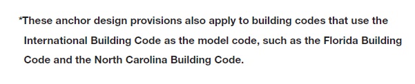
The International Building Code, beginning with the 2000 edition, describes the design methodology of concrete anchors by virtue of the language within the IBC itself, or through language in the Referenced Standard (ACI 318). In this technical bulletin, specific reference to the 2012 IBC and ACI 318-11 will be made, since this is currently the most widely adopted edition of the IBC.

cadp1.1

“Code Anchors” and “Alternative Materials”
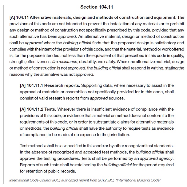
Anchors can be divided into two major categories: 1) “Code Anchors”, which are those that are specifically addressed in the IBC or its Referenced Standards, and 2) “Alternative Materials”, the design and qualification of which are not addressed in the IBC or its Referenced Standards.
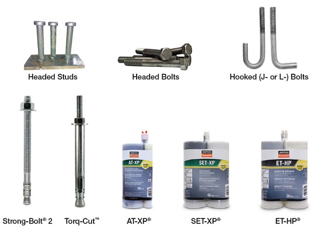
The following “Code Anchors” recognized by the 2012 IBC:

  • Headed studs
  • Headed bolts
  • Hooked (J- or L-) bolts
  • Expansion anchors(such as Simpson Strong-Tie® Strong-Bolt® 2)
  • Undercut anchors (such as Simpson Strong-Tie® Torq-Cut™)
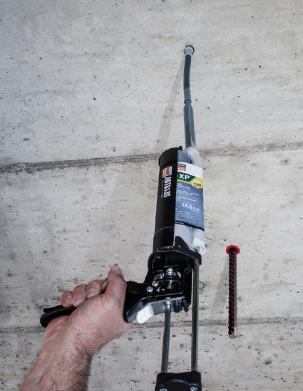
  • Adhesive anchors (such as Simpson Strong-Tie® SET-XP®, AT-XP®, and ET-HP®)

cadp1.2

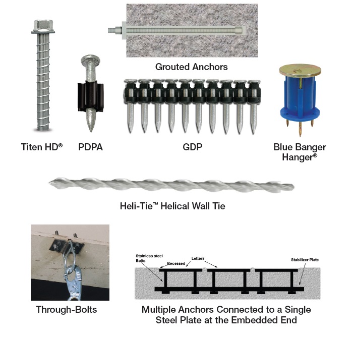
Anchor types not listed above are considered “Alternative Materials.”
The following are anchors qualified as such:

  • Screw anchors (such as Simpson Strong-Tie® Titen HD®)

Alternative materials also apply to anchor types specifically excluded from ACI 318-11 calculation and analysis requirements.

  • Specialty inserts (such as Simpson Strong-Tie® Blue Banger Hanger®)
  • Through-bolts
  • Multiple anchors connected to a single steel plate at the embedded end
  • Grouted anchors
  • Powder- or gas-actuated fasteners (such as Simpson Strong-Tie® PDPA)

cadp1.3

Designing “Code Anchors”
The starting point for the design of all anchors is Section 1908 of the 2012 IBC.

cadp1.4

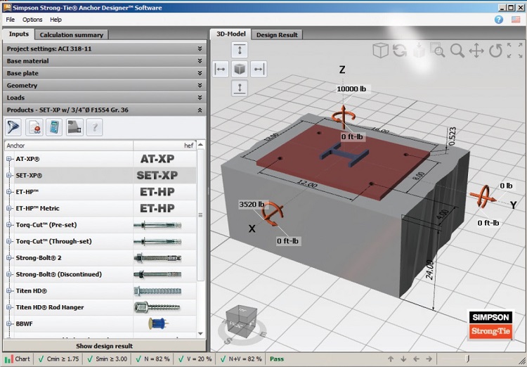
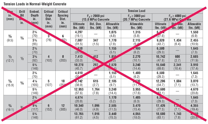
Section 1908.1 states that only cast-in-place headed bolts and headed studs are permitted to be designed using “Allowable Stress Design,” provided that they are not used to resist earthquake loads or effects. For these anchors, Section 1908.2 references Table 1908.2 for the determination of the allowable service load. Section 1908.1 makes explicit reference to post-installed anchors (anchors installed into hardened concrete), stating that the provisions of “Allowable Stress Design” is not permitted. For the design professional, this means that determining anchor by means of “Allowable Load Tables” based on previous test criteria that used a safety factor of 4.0 to determine allowable loads, as in the example below, is not permitted under the IBC.

cadp1.5

Section 1909 of the 2012 IBC, “Anchorage to Concrete – Strength Design” makes explicit reference to Appendix D of ACI 318 as the required design standard for the anchors listed in this section.

cadp1.6

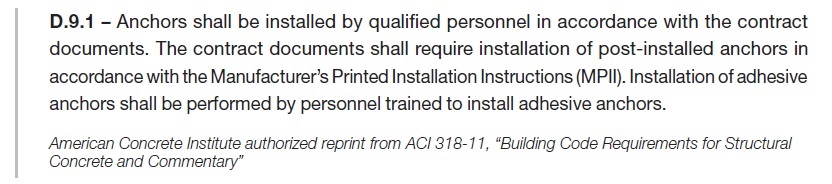
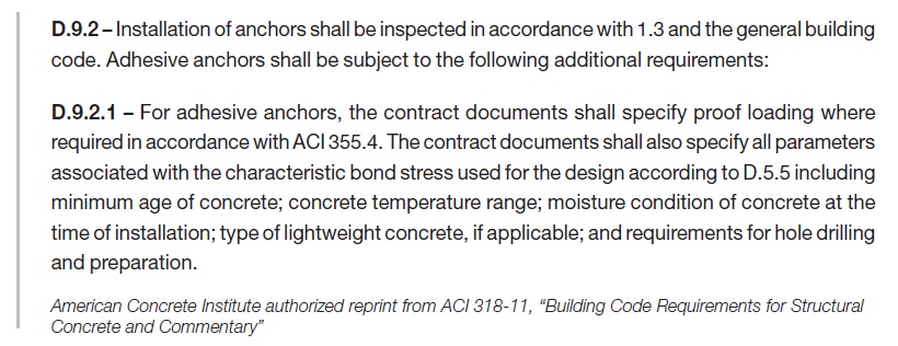
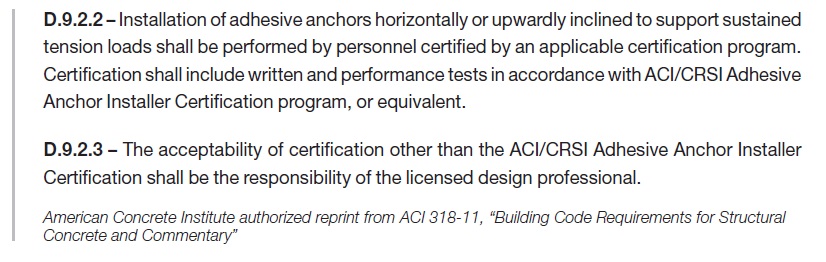
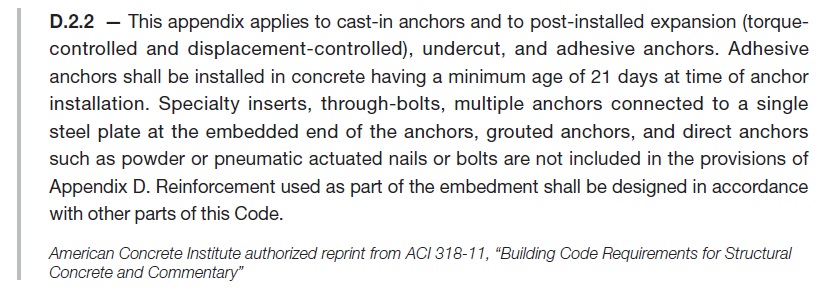
Cast-in-place headed bolts and headed studs used to resist earthquake loads or effects must be designed using “Strength Design” in accordance with ACI 318 Appendix D. Additionally, Section 1909 does not make reference to adhesive anchors, despite their status as “code anchors.” ACI 318-11 was the first edition to include adhesive anchors in its scope; however, the 2012 IBC was approved prior to the approval of ACI 318-11. This resulted in the omission of adhesive anchors from the language in Section 1909 of the 2012 IBC. Section 1901.3 of the 2015 IBC, entitled “Anchoring to Concrete” includes language for adhesive anchors and their applicability to the ACI 318-14 design and qualification requirements. The omission of adhesive anchors from Section 1909 of the 2012 IBC, however, does not exclude them from the design and qualification requirements of ACI 318-11 by virtue of their inclusion in ACI 318-11 Section D.2.2. The design professional must then reference Section D.2 of ACI 318-11, Appendix D to confirm that the anchors being designed fall within its scope.

cadp1.7

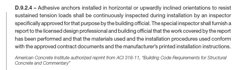
Note that anchors used for temporary construction means, such as tilt wall panel bracing, are not addressed in the IBC. As a result, they are not required to be designed in accordance with the provisions of ACI 318, Appendix D. Section D.2.2 lists anchor types that fall within its scope, and those that are excluded (considered “Alternative Materials”).

cadp1.8

Code Anchors are required to meet the ACI 318-11 Section D.2.3 qualification requirements described below.

cadp1.9

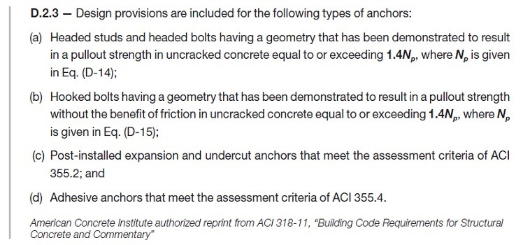
ACI 355.2 (Qualification standard for expansion and undercut anchors) and ACI 355.4 (Qualification standard for adhesive anchors) are referenced here as the qualification criteria for specific types of postinstalled anchors. For the design professional it can be difficult to determine, without fully investigating these Referenced Standards, whether a specific proprietary anchor has been tested and is qualified for use in concrete. A simpler means by which to identify whether a proprietary anchor has been qualified to the Referenced Standard is a current Research Report (e.g., Evaluation or Code Report) which provides third-party review and verification that the product has been tested to and meets the qualification standard. There are two primary Research Report providers: IAPMO UES (International Association of Plumbing & Mechanical Officials Uniform Evaluation Service) and ICC-ES (International Code Council Evaluation Service).
These agencies are ANSI ISO 17065 accredited. They review independent laboratory test data, witnessed or conducted by an accredited third party, for a product and verify its conformance to publicly developed and majority-approved qualification criteria (or acceptance criteria) established for a given anchor type. Research Reports are an invaluable tool to the design professional and building official as evidence of conformance with the IBC.

There are two acceptance criteria that apply to post-installed “Code Anchors”:

  • ICC-ES AC193 – Acceptance Criteria for Post-Installed Mechanical Anchors in Concrete Elements
  • ICC-ES AC308 – Acceptance Criteria for Post-Installed Adhesive Anchors in Concrete Elements

These acceptance criteria reference ACI 355.2 and ACI 355.4, respectively, as the foundation for the test program by which the anchor is evaluated, and establish minimum performance standards for qualification. A Research Report is issued for an anchor that meets these minimum standards.