

Modern construction schedules and conditions create a demand for solutions that can perform in a wide variety of environments. In the following post, Field Engineer Chris Johnson provides a rundown of different concrete and hole conditions for adhesive anchoring, the related design factors, and proper installation instructions and approved adhesive products for submerged anchorage.
Tag: adhesive anchor
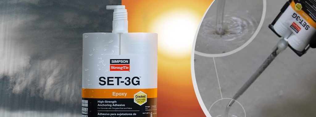
Reasons to Specify SET-3G Adhesive for Anchorage in Concrete Construction
We’ve been receiving a lot of requests lately from engineers wanting to know exactly what the difference is between Simpson Strong-Tie’s relatively new adhesive, SET-3G™, and its predecessor, SET-XP®. Both are epoxy-based adhesives used to anchor threaded rods and reinforcing bars in concrete base material for structural applications. If you perform a live pull test on a ½“-diameter mild steel rod embedded 4“ deep in 3,000 psi uncracked normal-weight concrete, the result will likely be the same; in both cases, the steel rod will break in a ductile manner at around 11 kips. You can see this hourglass-shaped steel failure mode happening in Figure 1. (To learn more about anchorage failure modes and ductility, check out this blog). Yet, the SET-3G design values shown in ESR-4057 come out ahead. But why?
How Should I Determine a Tension Test Load? Guidelines on Proof Loading Adhesive Anchors
Have you ever been involved on a project where a post-installed anchor failed when loaded? What was the circumstance? Was the anchor installed with incorrect torque or was the hole improperly cleaned, resulting in lower capacities than published? Unfortunately, in the world of concrete anchors, installations are sometimes incorrect as a result of not following instructions. Alternatively, perhaps you’re working on a project where special inspection wasn’t performed as required by the building code. What should be done in these cases?

Are You Ready to Design Post-Installed Anchors in Cracked Masonry?
Design criteria for cracked-concrete masonry units are finally available for adhesive anchors.
It has been over 15 years since cracked concrete changed the way anchorage to concrete was qualified and designed. The ICC International Building Code (IBC) 2003 referenced American Concrete Institute (ACI) 318-02 Appendix D as a design provision for both cast-in-place and post-installed anchors into concrete. Appendix D was the first introduction of cracked concrete to designers. These design provisions required mechanical anchors to be qualified per ACI 355.2, which mandated testing of anchors in cracks. The Masonry Society (TMS) 405 has not addressed cracks in concrete masonry units since the code’s introduction to concrete in 2003. The Concrete and Masonry Anchor Manufacturers Association (CAMA) has taken on the task of introducing cracked masonry unit testing, qualification and design by updating Acceptance Criteria AC58. These criteria were developed to address the testing and qualification of adhesive anchors in grouted, hollow, and partially grouted concrete masonry units, as well as in brick masonry units.
Overcoming Adhesive Anchor Orientation Challenges with the Piston Plug Adhesive Delivery System
Modern code-listed adhesive anchors offer high-strength connection solutions for a variety of applications. However, as in all construction projects, good product performance requires proper selection and installation. In this blog post, we will discuss the challenge of installation orientation and an accessory that can help installers more easily make proper adhesive anchor installations—the piston plug adhesive delivery system.
ACI 318-11 Appendix D (Anchoring to Concrete) calculations use a uniform bond stress model to calculate an adhesive anchor’s resistance to bond failure. According to this theory, an adhesive anchor is assumed to transfer applied loads into the concrete base material uniformly along its effective embedment depth, hef. The equation for an anchor’s basic bond strength (expressed in pounds of force) is simply the adhesive formulation’s bond strength per unit area (λ * τcr) multiplied by the idealized cylindrical surface area of the insert that is in contact with the adhesive (π * da * hef):
Nba = λ τcr π da hef (ACI 318-11, Eq. D-22)
 Although the model is a simplification of reality, the mathematical expression represents the core assumption that the adhesive is able to transfer stress completely along the entire depth of the anchorage. This is a key requirement in installation: Anchoring adhesives must be installed such that air entrapment and significant voids are prevented.
Downward installations (Figure 1) have historically presented relatively few challenges for adhesive injection in this regard. In such applications, gravity is helpful; the adhesive naturally flows to the bottom of the drilled hole while being dispensed from the cartridge through a static mixing nozzle. The installer maintains the open end of the nozzle below the free surface of the adhesive until the drilled hole is filled to the desired level. For deep holes, extension tubing is affixed to the open end of the nozzle to increase reach. This procedure avoids entrapping air bubbles in the adhesive material.
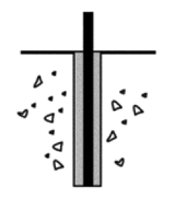
Installations into horizontal, upwardly inclined or overhead drilled holes (Figure 2) require more care on the part of adhesive anchor installers. Although the installation principle to avoid entrapping air is similar for these orientations, a key difference is that gravity does not help to keep the adhesive towards the “bottom” (deepest point) of the drilled hole. At worst, it can work against the installer when ambient temperatures may cause the adhesive to run out of the hole during injection. These adhesive anchor installations can be more difficult for an untrained installer and can slow the rate of work. This is one of the reasons that ACI 318-11 Section D.9.2.4 requires continuous special inspection of adhesive anchor installations in these three orientations when the application is also intended to resist sustained loads.

(Source: ACI 318-11, Section RD.1)
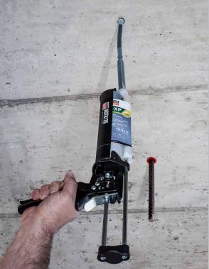
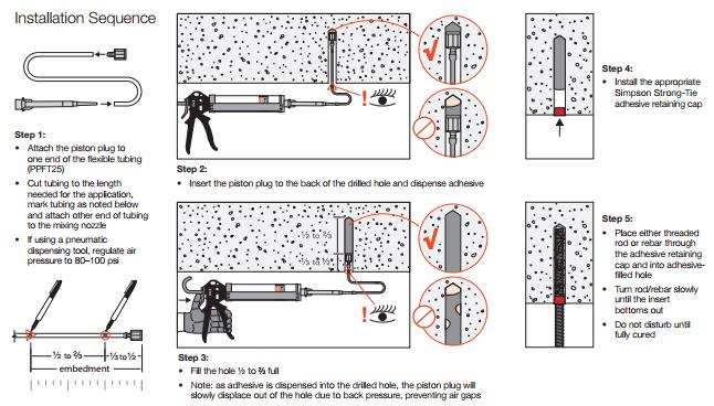
To aid the installer, Simpson Strong-Tie offers a piston plug adhesive delivery system (Figure 3). Consisting of pre-packaged flexible tubing, piston plugs and an adhesive retaining cap, this system allows installers to more easily and consistently make high-quality installations while completing their work efficiently. The installation sequence is provided in Figure 4.
The system consists of three components:
- Piston plug – The key component of the system, it is slightly smaller in diameter than the drilled hole. As the adhesive is dispensed into the drilled hole, the piston plug is displaced out of the hole by the advancing volume of the injected adhesive. The displacement creates a more positive feel for the installer to know where the free surface of the adhesive is.
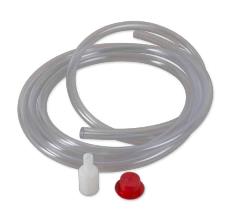
- Flexible tubing – For use with the piston plug to facilitate injection at the deepest point of the drilled hole.
- Adhesive retaining cap – Provided to prevent adhesive material from flowing out of the drilled hole after dispensing and to provide a centering mechanism for the insert. For heavy inserts in overhead conditions, other means must be provided to carry the weight of the insert and prevent it from falling or becoming dislodged from the hole before the adhesive has fully cured.
What do you think about the piston plug adhesive delivery system? Let us know by posting a comment below.
New Simpson Strong-Tie Anchor Designer software
Remember back to the days when you used allowable stress design for designing anchorage to concrete? Once you had your design loads, selecting an anchor was quick and easy. The 1997 UBC covered the anchorage to concrete in less than two pages, so the calculation was painless. Post-installed anchors were even easier, since allowable loads were tabulated and you just needed to apply a couple of edge distance and spacing reductions.
Since the introduction of strength design provisions and the adoption of ACI 318 Appendix D, first in the 2000 IBC, designing code-compliant anchorage to concrete has become much more complex. At least once (and probably not more) armed with a pencil, calculator, and an eraser, most of us have set out to design a ‘simple’ anchorage to concrete connection using the Appendix D provisions. Several pages of calculations later (and hopefully with a solution to the problem), most of us, I imagine, came to realize that designing anchorages to concrete by hand required much more time and effort than we anticipated or could allocate time for. As a result, many of us probably created an Excel template to speed up the design process using built-in functions and some Visual Basic programming.
The question is: are you still using the template?
For me, the answer is an emphatic “NO”, mainly because the spreadsheet I created has limited capability given the complexity in adapting the design methodology to complex anchor layouts, changes to the design provisions with each new code edition, and the need to add/modify data each time a new post-installed anchor product is introduced.