

 You might wonder what a quote about winning basketball games could possibly have to do with snow loading on trusses. As with basketball, the importance of close teamwork also applies to a project involving metal-plate-connected wood trusses – for the best outcome, the whole team needs to be on the same page. For purposes of this blog post, the team includes the Building Designer, the Truss Designer and the Building Official, and the desired outcome is not a win per se, but rather properly loaded trusses. Snow loading on trusses is one area where things may not always go according to the game plan when everyone isn’t in accord. This post will explain how to avoid some common miscommunications about truss loading.
Tag: ASCE 7
Seismic Bracing Requirements for Nonstructural Components
Have you ever been at home during an earthquake and the lights turned off due to a loss of power? Imagine what it would be like to be in a hospital on an operating table during an earthquake or for a ceiling to fall on you while you are lying on your hospital bed.
Open Front Structure Wind Pressure Design
We received a request from Martin H., one of our blog readers, to discuss the method for determining roof wind pressures on an open front agricultural building. The inquiry was regarding clarification on analyzing the roof pressure when a combined external and interior pressure exists and whether these are additive.
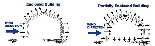
As can be seen in the above illustrations, the net design pressure on the roof is the sum of the uplift on the exterior surface and the uplift on the interior surface from any internal pressure. ASCE 7 provides a method for determining this pressure. Specifically, ASCE 7-10 will be used for the remainder of this post. Assuming the three remaining sides of the open front structure are walls without openings, the building will be classified as partially enclosed by the definitions of Section 26.2.
ASCE 7-10 provides for two methods for determining the Main Wind Force Resisting System (MWFRS) wind loads for partially enclosed buildings, the Directional Procedure in Chapter 27, and the Envelope Procedure in Chapter 28.
When using the Directional Procedure, the net wind load is calculated using the following equation:
P = qGCp – qi(GCpi)
When using the Envelope Procedure, the net wind load is calculated using the following equation:
P = qh[(GCpf) – (GCpi)]
In each of these equations, the first portion determines the pressure on the exterior surface, and the second portion determines the pressure on the interior surface. So the variable for calculating the internal pressure is the internal pressure coefficient GCpi.
The internal pressure coefficient is provided in Table 26.11-1 based on three different categories of building enclosure.
Enclosure Classification | (GCpi) |
| Open Buildings | 0.00 |
| Partially Enclosed Buildings | +0.55 -0.55 |
| Enclosed Buildings | +0.18 -0.18 |
Table 26.11-1
In the case of an open front structure, it is assumed that the partially enclosed internal pressure coefficient must be used. This coefficient is 3x greater than when the building envelope is classified as enclosed. Use of this higher coefficient in the design will account for the interior pressure on the underside of the roof combined with the exterior pressure.
MWFRS versus C&C
Another somewhat related question: to what level loads should the roof anchorage forces be calculated, MWFRS or C&C (Component and Cladding)? I have often been asked this question, and wrote a Technical Note published by CFSEI (Cold-Formed Steel Engineers Institute) in July 2009.
What are your thoughts?
– Sam
What are your thoughts? Visit the blog and leave a comment!
Flexible or Rigid? Multi-Story Light-Frame Structure Design Considerations
I like to think I’m flexible, but I’ve been accused of being rigid at times. I guess that’s what therapy is for. If you were to ask a light-frame structure diaphragm that same question, you would likely get multiple conflicting answers. The 1988 UBC first introduced parameters to evaluate diaphragm rigidity. Earthquake Regulations Section 2312(e)6 stated:

Provision shall be made for the increased shears resulting from horizontal torsion where diaphragms are not flexible. Diaphragms shall be considered flexible for the purposes of this paragraph when the maximum lateral deformation of the diaphragm is more than two times the average story drift of the associated story. This may be determined by comparing the computed midpoint in-plane deflection of the diaphragm under lateral load with the story drift of adjoining vertical resisting elements under equivalent tributary lateral load.