

The majority of Simpson Strong-Tie fasteners are used to secure small, solid-sawn lumber and engineered wood members. However, there is a segment in the construction world where large piles are the norm. Pile framing is common in piers along the coast, elevated houses along the beach, and docks and boardwalks.
While the term “pile” is generic, the piles themselves are not generic. They come in both square and round shapes, as well as an array of sizes, and they vary greatly based on region. The most common pile sizes are 8 inches, 10 inches, and 12 inches, square and round, but they can be found in other sizes. The 8-inch and 10-inch round piles are usually supplied in their natural shape, while 12-inch round piles are often shaped to ensure a consistent diameter and straightness. All piles are preservative-treated.
Historically, the attachment of framing to piles has been done with bolts. This is a very labor-intensive method of construction, but for many years there was no viable fastener alternative. Two years ago, however, Simpson Strong-Tie introduced a new screw, the Strong-Drive® SDWH Timber-Hex HDG screw (SDWH27G), specifically designed for pile- framing construction needs. It can be installed without predrilling and is hot-dip galvanized (ASTM A153, Class C) for exterior applications.

Simpson Strong-Tie tested a number of different pile-framing connections that can be made with the SDWH27G screw. This blog post will highlight some of the tested connections. More information can be found in the following three documents on our website:
- The flier for the SDWH Timber-Hex HDG screw: F-FSDWHHDG14 found here.
- The engineering letter for Square Piles found here.
- The engineering letter for Round Piles found here.
The flier provides product information, and the engineering letters include dimensional details for common pile-framing connections that were tested.
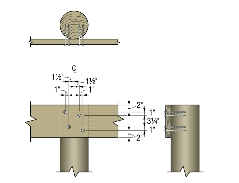
Piles are typically notched or coped to receive a horizontal framing member called a “stringer.” The coped shoulder provides bearing for the stringer and serves as a means of transferring gravity load to the pile. The SDWH27G can be used to fasten framing to coped and non-coped round and square piles.
The connections that we tested can be put into four general groups that include both round and square piles:
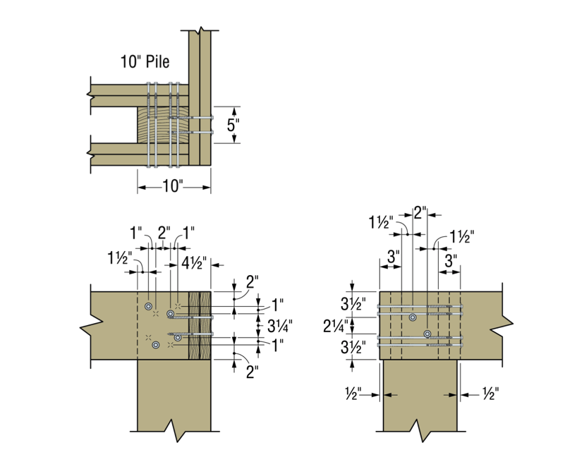
- Two-side framing on coped and non-coped piles
- One–side framing on coped and non-coped piles
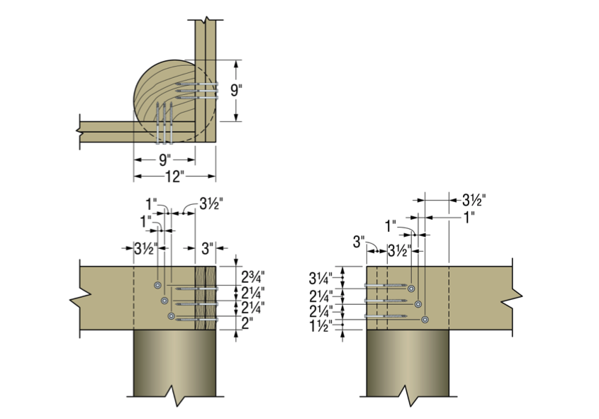
- Corner framing on coped piles
- Bracing connections
Additionally, the testing program included four different framing materials in several thicknesses and depths:
- Glulam
- Parallam
- Sawn lumber
- LSL/LVL
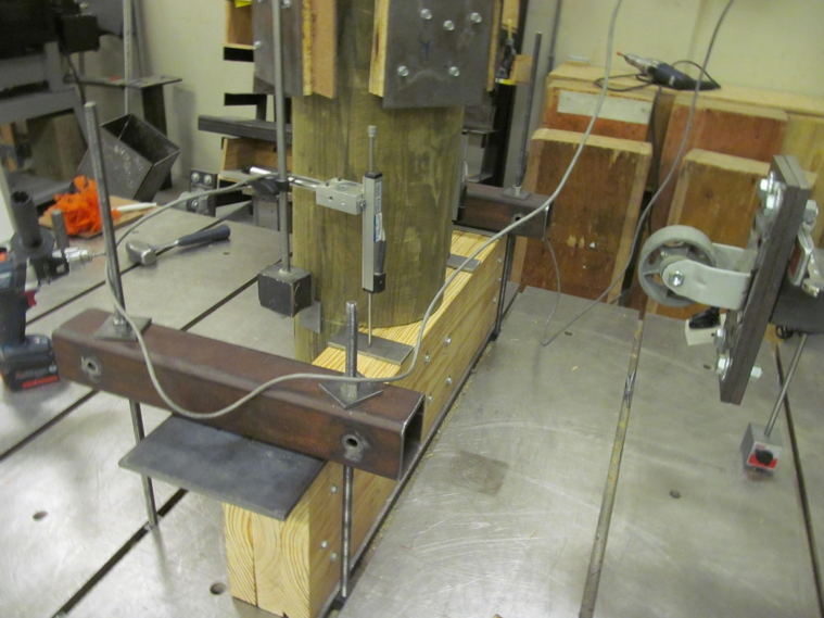
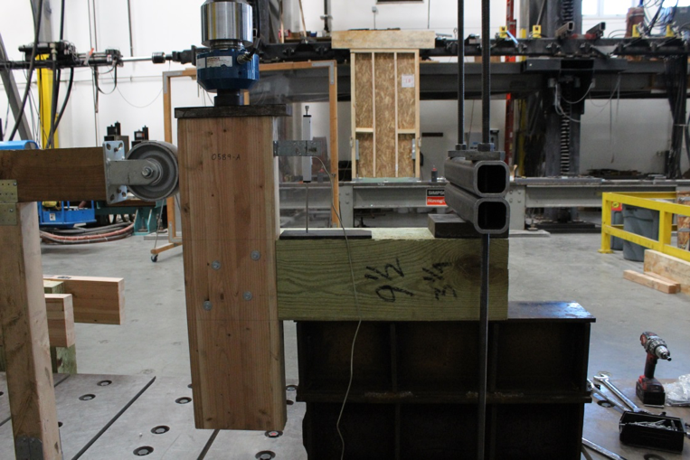
The total testing program included more than 50 connection conditions that represented pile shape and size, framing material and thickness and framing orientation and details. We assigned allowable uplift and lateral properties to the tested connections using the analysis methods of ICC-ES AC13. Figures 2 and 3 show some of the tested assemblies.
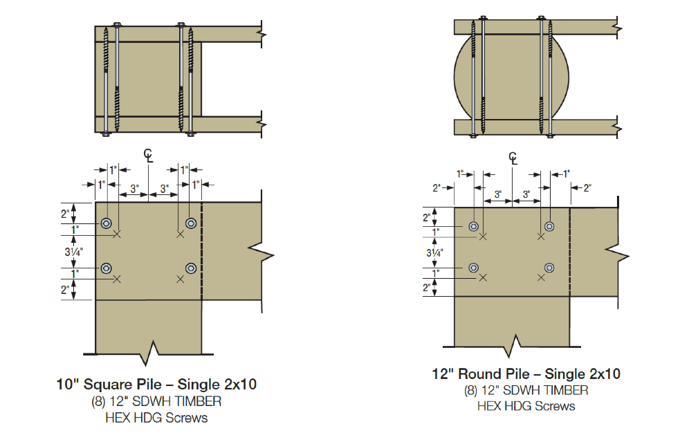
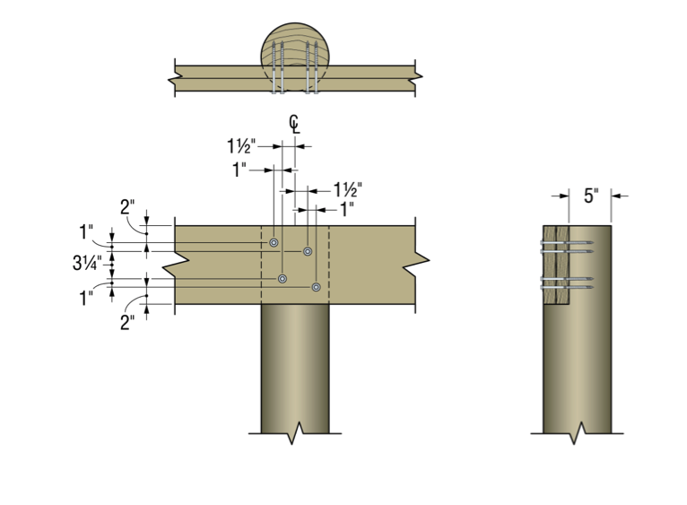
Figures 4 through 9 illustrate some of the connections and details that are presented in the flier and engineering letters.
Some elements of practice are important to the design of pile-framing connections. Some of the basic practices include:
- For coped connections, the coped section shall not be more than 50% of the cross-section.
- For coped connections, the coped shoulder should be as wide as the framing member(s).
- Fastener spacing is critical to the capacity of the connection.
- When installing fasteners from two directions, lay out the fasteners so that they do not intersect.
In many cases, pile-framing connections use angled braces for extra lateral support. The SDWH27G can be used in these cases too.

In the flier and engineering letters previously referenced, you will find allowable loads and specific fastener specifications for many combinations of stringer and pile types and sizes.
What have you seen in your area? Let us know – perhaps we can add your conditions to our list.