Florida Product Approvals Made Simple

florida1

This year, the new 5th Edition of the Florida Building Code was released and is now in effect statewide. First printed in 2002, the Florida Building Code was developed as part of Florida’s response to the destruction caused by Hurricane Andrew and other hurricanes in the state.

Another component, which I would like to take a closer look at in today’s post, is a separate Florida Product Approval system designed to be a single source for approval of construction products for manufacturers, Designers and code enforcers. This single system streamlines the previous approach of different procedures for product approval in different jurisdictions. While statewide approval is not required, many jurisdictions, manufacturers and specifiers prefer using the statewide system to the alternative, which is called local product approval. To ensure uniformity of the state system, Florida law compels local jurisdictions to accept state-approved products without requiring further testing and evaluation of other evidence, as long as the product is being used consistent with the conditions of its approval.

The rules of the Florida Product Approval system are in Florida Rule 61G20-3. Here is some basic information about Florida Product Approval.

The Florida Product Approval system is only available for “approval of products and systems, which comprise the building envelope and structural frame, for compliance with the structural requirements of the Florida Building Code.” So users will only find certain types of products approved there. However, if you work in areas where design for wind resistance is required, the Florida system can be a gold mine of information for tested, rated and evaluated products. Not only will you find products like Simpson Strong-Tie connectors with our ICC-ES and IAPMO UES evaluation reports, but thousands of other tested and rated windows, doors, shutters, roof covering materials and other products that don’t typically get evaluation reports from national entities. The specific categories of products covered under the Florida system are exterior doors, impact protective systems, panel walls, roofing, shutters, skylights, structural components and windows.

To protect consumers, a recent law passed in Florida states that a product may not be advertised, sold or marketed as offering protection from hurricanes, windstorms or wind-borne debris unless it has either State Product Approval or local product approval. Selling unapproved products in this way is considered a violation of the Florida Deceptive and Unfair Trade Practices Act.

Once a manufacturer understands the process for achieving a statewide approval, it is not difficult to achieve, but it can be expensive. The manufacturer must apply on the State of Florida Building Code Information System (BCIS) website at www.floridabuilding.org. To prove compliance with the code, the manufacturer must upload either a test report, a product certification from an approved certification entity, an evaluation report from a Florida Professional Engineer or Architect, or an evaluation report from an approved evaluation entity (ICC-ES, IAPMU UES, or Miami-Dade County Product Control). Then, the manufacturer must hire an independent validator to review the application to ensure it complies with the Product Approval Rule and that there are no clerical errors. Finally, once the validation is complete, staff from the Department of Business and Professional Regulation reviews the application. Depending on the method used to indicate code compliance, the application may be approved at that time or it may have to go through additional review by the Florida Building Commission.

Here are several ways to find out if a product is approved.

  1. For Simpson Strong-Tie products, we maintain a page on www.strongtie.com that lists our Florida Product Approvals.
  2. The Florida Department of Business and Professional Regulation maintains a page where users can search Product Approvals by categories such as manufacturer, category of product, product name, or other attributes such as impact resistance or design pressure.
  3. A third-party group we work with has created a website called www.ApprovalZoom.com that lists various product evaluations and product approvals. In addition to listing Florida Product Approvals, they also list ICC-ES evaluation reports, Miami-Dade County Notices of Acceptance, Texas Department of Insurance Approvals, Los Angeles Department of Building Safety Approvals, AAMA certifications and Keystone certifications among others.
florida3
Florida Department of Business and Professional Regulation Product Approvals search

The process for searching for approved products on the Florida BCIS is fairly simple.

  1. Go to www.floridabuilding.org
  2. On the menu on the left side of the page, click on Product Approval. Or, click this link to go directly to the search page.
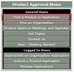
  3. On the Product Approval Menu, click on Find a Product or Application. Note that at this location you can also search for approved organizations such as certification agencies, evaluation entities, quality assurance entities, testing laboratories and validation entities.
  4. Ensure the proper Code Version is shown. The current 2014 Florida Code is based on the 2012 International Codes.
  5. At this point, several options can be searched. You can search for all approvals by a specific product manufacturer or a certain type of building component by searching Category and Subcategory, or if searching for a specific product, by entering the manufacturer’s name and the product name.
florida2
Select the option highlighted in red

I hope you find the information contained in the Florida Product Approval system useful. Do you have other needs to find approved products?

Design Examples for Steel Deck Diaphragm Calculator Web App

This week’s blog post was written by Neelima Tapata, R&D Engineer for Fastening Systems. She works in the development, testing and code approval of fasteners. She joined Simpson Strong-Tie in 2011, bringing 10 years of design experience in multi- and single-family residential structures in cold-formed steel and wood, curtain wall framing design, steel structures and concrete design. Neelima earned her bachelor’s degree in Civil Engineering from J.N.T.U in India and M.S. in Civil Engineering with a focus on Structural Engineering from Lamar University. She is a registered Professional Engineer in the State of California.

Like most engineers, you are probably often working against tight deadlines,  on multiple projects and within short delivery times. If you have ever wished for a design tool that would make your work easier, we have an app for that. It’s a simple, quick and easy-to-use tool called the “Steel Deck Diaphragm Calculator” for designing steel deck diaphragms. This tool is so user friendly you can start using it in minutes without spending hours in training. This app can be found on our website, and you don’t need to install anything.

The Steel Deck Diaphragm Calculator has two parts to it: “Optimized Solutions” and “Diaphragm Capacity Tables.” Optimized Solutions is a Designer’s tool and it offers optimized design solutions based on cost and labor for a given shear and uplift. The app provides multiple solutions starting with the lowest cost option using different Simpson Strong-Tie® structural and side-lap fasteners. Calculations can be generated for any of the solutions and a submittal package can be created with the code reports, Factory Mutual Approval reports, fastener information, corrosion information, available fliers, and SDI DDM03 Appendix VII and Appendix IX that includes Simpson Strong-Tie fasteners. Currently, this tool can be used for designing with only Simpson Strong-Tie fasteners. We will be including weld options in this calculator very soon. Stay tuned!

The Diaphragm Capacity Tables calculator can be used to develop a table of diaphragm capacities based on the effects of combined shear and tension.

steeldeck1

When “Optimized Solutions” is selected, the following input is requested:

Step 1: Building Information   ̶   Enter general information about the project, like the project name, the length and width of the building to be designed along with spacing between the support members such as joist spacing, is entered.

Step 2: Steel Deck Information   ̶   Select the type of the steel deck along with the fill type. You can select the panel width from the options or select “Any panel width” option for the program to design the panel width. Choose the deck thickness or select the “Optimize” option for the program to design the optimum deck thickness. You also have an option of editing the steel deck properties to accommodate proprietary decks that are within the limitations of SDI DDM03 Section 1.2. Select the joist steel (support) thickness that the deck material will be attached to. For some fasteners, the shear strength of the fastener is dependent on this support thickness.

Step 3: Load Information   ̶  Enter the shear and uplift demand and select the load type as either “wind” or “seismic” and the design method as “ASD” or “LRFD.”

Step 4: Fastener Information   ̶  This is the last step of input before designing. In the fastener information section, you have the option to choose a structural and side-lap fastener or let the program design the most cost-effective structural and side-lap options. This can be done by checking the “Provide optimized solutions” option. The default options in the program are usually the best choice. However, you can change or modify as needed for your project. You can also set the side-lap fastener range or leave it to the default of 0 to 12 fasteners.

Now let’s work on an example:

Design a roof deck for a length of L = 500 ft. and a width b = 300 ft. The roof deck is a WR (wide rib) type panel, with a panel width of 36″.  The roof deck is supported by joists that are ¼” thick and spaced at 5 ft. on center. Design the diaphragm for wind loading using Allowable Stress Design method. The diaphragm should be designed for a diaphragm shear of 1200 plf. and a net uplift of 30 psf. The steel deck is ASTM A653 SS Grade 33 deck with Fu = 45 ksi.

This information is entered in the web app, as seen below.

steeldeck2

After inputting all the information, click on the Calculate button. You will see the five best solutions sorted by lowest cost and least amount of labor. Then click on the Submittal Generator button. Upon pressing this button, a new column called “Solution” is added with an option button for each solution. You can select any of the solutions. Below the Submittal Generator button, you can select various Code Reports and Approvals and Notes and Information selections that you want included in the submittal. After selecting these items, click on the Generate Submittal button. Now a pdf package will be generated with all of your selections.

steeldeck3

Below is the screen shot of the first page containing Table of Contents from the PDF copy generated. The PDF copy contains the solutions generated by the program, then the detailed calculations for the solution that is selected. In this case, as you can see in the screen shot above, detailed calculations for solution #1 are included with XLQ114T1224 structural screws; XU34S1016 side-lap screws; 36/9 structural pattern and with (10) side-lap fasteners; diaphragm shear strength of 1205 plf. and diaphragm shear stiffness of 91.786 kip/in. The detailed calculations are followed by IAPMO UES ER-326 code report and FM Approval report #3050714.

steeldeck4

Below is another example of a roof deck to be designed for multiple zones.

Design a roof diaphragm that will be zoned into three different areas. Zoning is a good way to optimize the economy of the roof diaphragm. Below are the required diaphragm shears and uplift in the three zones.

Zone 1: Diaphragm shear = 1200 plf.; Net uplift = 30 psf.; Length and width of zone 1 = 300 ft. x 200 ft.
              Joist spacing = 5 ft.

Zone 2: Diaphragm shear = 1400 plf.; Net uplift = 0 psf.; Length and width of zone 2 = 500 ft. x 200 ft.
              Joist spacing = 5.5 ft.

Zone 3: Diaphragm shear = 1000 plf.; Net uplift = 25 psf.; Length and width of zone 3 = 300 ft. x 200 ft.
              Joist spacing = 4.75 ft.

Refer to the example above for all other information not given.

To design for multiple zones first select the Multi-Zone Input button, which is below the Fastener Information section as shown below:

steeldeck5

When you click on the Multi-Zone Input button, you can see a toggle button appearing above a few selections as shown below. The default for the toggle button is globalbutton
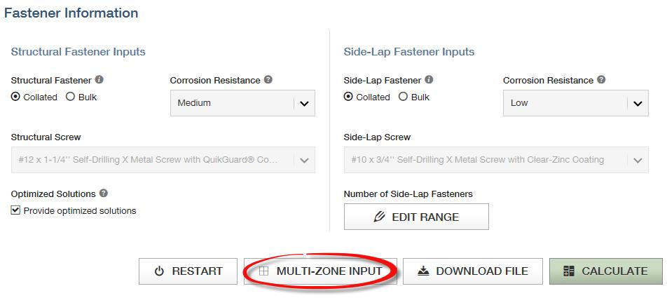
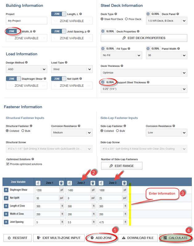
, which means that this selection is same for all the zones. You can click on the toggle button to change to zonebutton. Then the selection below changes to a label and reads Zone Variable. After all the selections that need to be zone variables are selected, click the Add Zone button. Keep adding zones as needed. A maximum of five zones can be added. After creating the zones, add the information for each zone and click the Calculate button.

steeldeck6

When the Calculate button is clicked, the results for each zone are listed. The five best solutions are listed for each of the zones as shown below.

steeldeck7

Similar to previous example, select the Generate Submittal button to select the solutions to be included in the submittal generator. Select one solution for each zone and then check the items like the code reports or notes to be included in the submittal. Click Generate Submittal to create the submittal package.

See the screen shot below for the steps.

steeldeck8

Now that you know how easy it is to design using our web app, use this app for your future projects. We welcome your feedback on features you find useful as well as your input on how we could make this program more useful to suit your needs. Let us know in the comments below.


Code Reports: Uniform Application of Code Intent in a Diverse Environment

Woodworks invited me to do a presentation on Testing and Evaluation of Products for Wood-framed Construction, and I found you can’t really talk about testing without talking about the test standards and criteria used in product evaluations. Usually the goal in testing to these standards is to show compliance with the intent of the building code and have the product listed in a code report.

Why not just follow the code?

Innovative architectural and structural building products not addressed by the building code are in every building. Revisions to the building code are considered on a three-year cycle and some standards are on a five-year cycle. Sometimes it may take several cycles to address a new building product.

Continue Reading