

There’s a saying in Chicago, “If you don’t like the weather, just wait fifteen minutes.” That’s especially true in the spring, when temperatures can easily vary by over 50° from one day to the next. As the temperature plunges into the blustery 30s one evening following a sunny high in the 80s, I throw my jacket on over my T-shirt, and I’m reminded that large swings in temperature tend to bring about changes in behavior as well. This isn’t true just with people, but with many materials as well, and it brings to mind a thermal process called heat treating. This is a process that is used on some concrete anchoring products in order to make them stronger and more durable. You may have heard of this process without fully understanding what it is or why it’s useful. In this post, I will try to scratch the surface of the topic with a very basic overview of how heat treating is used to improve the performance of concrete anchors.Continue Reading
Tag: concrete anchors
4 Common FRP Myths and Misconceptions: The Stuff Not Everyone Talks About
The primary benefit of fiber-reinforced polymer (FRP) systems as compared with traditional retrofit methods is that significant flexural, axial or shear strength gains can be realized using an easy-to-apply composite that does not add significant weight or section to the structure. Many times it is the most economical choice given the reduced preparation and labor costs and may be installed without taking the structure out of service. However, it is important to make sure the composite is properly designed following industry standards in order to ensure that it is the right product for the application.
To provide you with a better understanding of the topic, it’s important to dispel some common myths and misconceptions that you might hear about FRP:
Concrete Anchor Design for the International Building Code: Part 1
Purpose
The intent of this technical bulletin is to clarify code language and outline the correct path for the design of concrete anchors under the International Building Code (IBC). The reader will be able to clearly distinguish between “code anchors” and anchors that are considered “alternative materials,” as well as understand the logical sequence of code language for designing each type. The distinction between “cracked” concrete and “uncracked” concrete anchor design will be made. This technical bulletin will lend clarity to the qualification of post-installed anchors for use in concrete. Excerpts from the IBC and its Referenced Standards will be provided to facilitate the description of the design requirements.
Background
More than a decade after the introduction of the American Concrete Institute’s ACI 318, Appendix D design methodology for anchor design in 2002, many design professionals either do not fully understand or are unaware of the code requirements for the design of concrete anchors. Several factors contribute to the challenges associated with understanding the code mandates:
1. The incorrect notion that ACI 318, Appendix D is exclusively for anchors designed for “cracked concrete,” leading to regionally varying degrees of enforcement and implementation of the design requirements
2. Multiple Reference Standards for the design and qualification of different anchor types
3. The evolving scope of Reference Standards, which have reclassified some anchors as “Code Anchors” that were previously considered “Alternative Materials”
4. Confusing language in IBC sections that address concrete anchorage
5. Complexity of the anchor design methodology itself
6. Varying levels of special inspections enforcement
It is nevertheless incumbent upon the licensed design professional to design anchors in accordance with the minimum provisions of the code in order to protect public safety, reduce liability risk and fulfill professional responsibilities.
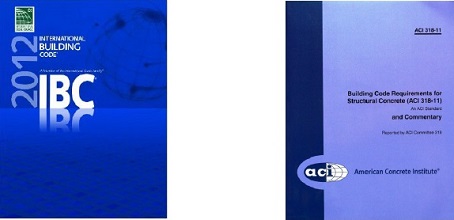
The International Building Code, beginning with the 2000 edition, describes the design methodology of concrete anchors by virtue of the language within the IBC itself, or through language in the Referenced Standard (ACI 318). In this technical bulletin, specific reference to the 2012 IBC and ACI 318-11 will be made, since this is currently the most widely adopted edition of the IBC.
“Code Anchors” and “Alternative Materials”
Anchors can be divided into two major categories: 1) “Code Anchors”, which are those that are specifically addressed in the IBC or its Referenced Standards, and 2) “Alternative Materials”, the design and qualification of which are not addressed in the IBC or its Referenced Standards.
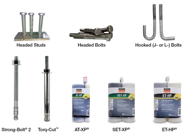
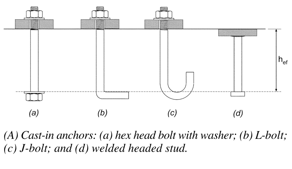
The following “Code Anchors” recognized by the 2012 IBC:
- Headed studs
- Headed bolts
- Hooked (J- or L-) bolts
- Expansion anchors(such as Simpson Strong-Tie® Strong-Bolt® 2)
- Undercut anchors (such as Simpson Strong-Tie® Torq-Cut™)
- Adhesive anchors (such as Simpson Strong-Tie® SET-XP®, AT-XP®, and ET-HP®)
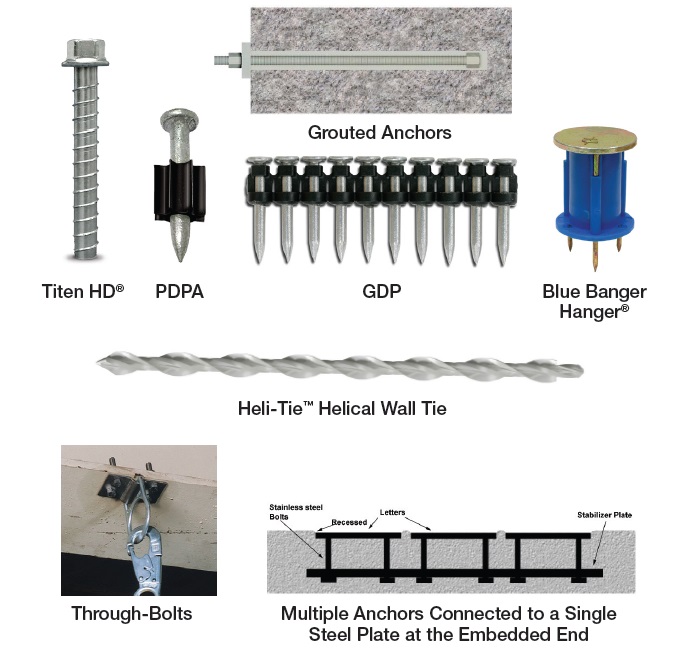
Anchor types not listed above are considered “Alternative Materials.”
The following are anchors qualified as such:
- Screw anchors (such as Simpson Strong-Tie® Titen HD®)
Alternative materials also apply to anchor types specifically excluded from ACI 318-11 calculation and analysis requirements.
- Specialty inserts (such as Simpson Strong-Tie® Blue Banger Hanger®)
- Through-bolts
- Multiple anchors connected to a single steel plate at the embedded end
- Grouted anchors
- Powder- or gas-actuated fasteners (such as Simpson Strong-Tie® PDPA)
Designing “Code Anchors”
The starting point for the design of all anchors is Section 1908 of the 2012 IBC.
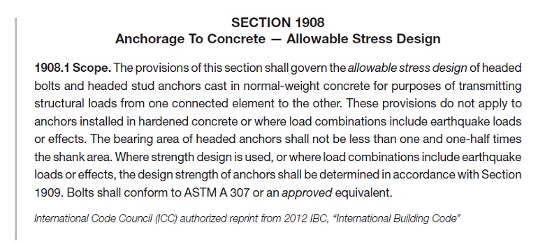
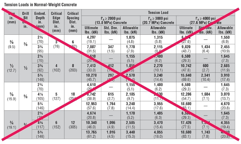
Section 1908.1 states that only cast-in-place headed bolts and headed studs are permitted to be designed using “Allowable Stress Design,” provided that they are not used to resist earthquake loads or effects. For these anchors, Section 1908.2 references Table 1908.2 for the determination of the allowable service load. Section 1908.1 makes explicit reference to post-installed anchors (anchors installed into hardened concrete), stating that the provisions of “Allowable Stress Design” is not permitted. For the design professional, this means that determining anchor by means of “Allowable Load Tables” based on previous test criteria that used a safety factor of 4.0 to determine allowable loads, as in the example below, is not permitted under the IBC.
Section 1909 of the 2012 IBC, “Anchorage to Concrete – Strength Design” makes explicit reference to Appendix D of ACI 318 as the required design standard for the anchors listed in this section.
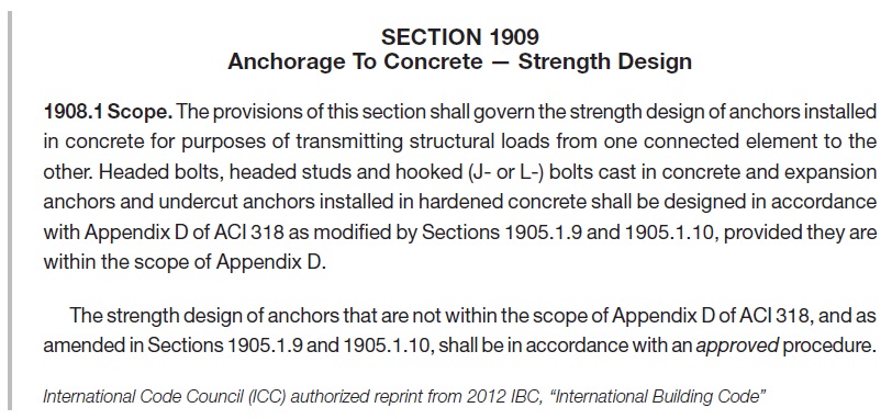
Cast-in-place headed bolts and headed studs used to resist earthquake loads or effects must be designed using “Strength Design” in accordance with ACI 318 Appendix D. Additionally, Section 1909 does not make reference to adhesive anchors, despite their status as “code anchors.” ACI 318-11 was the first edition to include adhesive anchors in its scope; however, the 2012 IBC was approved prior to the approval of ACI 318-11. This resulted in the omission of adhesive anchors from the language in Section 1909 of the 2012 IBC. Section 1901.3 of the 2015 IBC, entitled “Anchoring to Concrete” includes language for adhesive anchors and their applicability to the ACI 318-14 design and qualification requirements. The omission of adhesive anchors from Section 1909 of the 2012 IBC, however, does not exclude them from the design and qualification requirements of ACI 318-11 by virtue of their inclusion in ACI 318-11 Section D.2.2. The design professional must then reference Section D.2 of ACI 318-11, Appendix D to confirm that the anchors being designed fall within its scope.
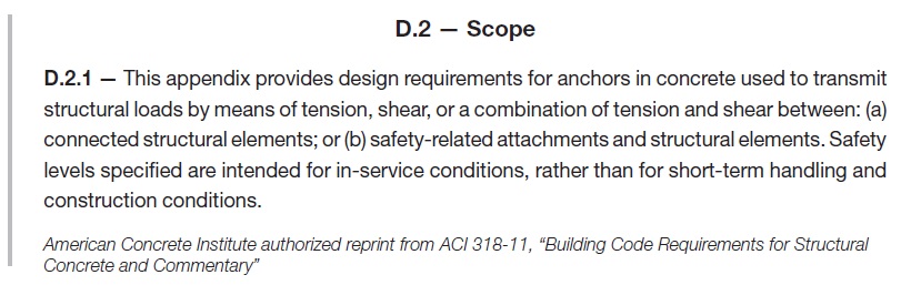
Note that anchors used for temporary construction means, such as tilt wall panel bracing, are not addressed in the IBC. As a result, they are not required to be designed in accordance with the provisions of ACI 318, Appendix D. Section D.2.2 lists anchor types that fall within its scope, and those that are excluded (considered “Alternative Materials”).
Code Anchors are required to meet the ACI 318-11 Section D.2.3 qualification requirements described below.
ACI 355.2 (Qualification standard for expansion and undercut anchors) and ACI 355.4 (Qualification standard for adhesive anchors) are referenced here as the qualification criteria for specific types of postinstalled anchors. For the design professional it can be difficult to determine, without fully investigating these Referenced Standards, whether a specific proprietary anchor has been tested and is qualified for use in concrete. A simpler means by which to identify whether a proprietary anchor has been qualified to the Referenced Standard is a current Research Report (e.g., Evaluation or Code Report) which provides third-party review and verification that the product has been tested to and meets the qualification standard. There are two primary Research Report providers: IAPMO UES (International Association of Plumbing & Mechanical Officials Uniform Evaluation Service) and ICC-ES (International Code Council Evaluation Service).
These agencies are ANSI ISO 17065 accredited. They review independent laboratory test data, witnessed or conducted by an accredited third party, for a product and verify its conformance to publicly developed and majority-approved qualification criteria (or acceptance criteria) established for a given anchor type. Research Reports are an invaluable tool to the design professional and building official as evidence of conformance with the IBC.
There are two acceptance criteria that apply to post-installed “Code Anchors”:
- ICC-ES AC193 – Acceptance Criteria for Post-Installed Mechanical Anchors in Concrete Elements
- ICC-ES AC308 – Acceptance Criteria for Post-Installed Adhesive Anchors in Concrete Elements
These acceptance criteria reference ACI 355.2 and ACI 355.4, respectively, as the foundation for the test program by which the anchor is evaluated, and establish minimum performance standards for qualification. A Research Report is issued for an anchor that meets these minimum standards.
Overcoming Adhesive Anchor Orientation Challenges with the Piston Plug Adhesive Delivery System
Modern code-listed adhesive anchors offer high-strength connection solutions for a variety of applications. However, as in all construction projects, good product performance requires proper selection and installation. In this blog post, we will discuss the challenge of installation orientation and an accessory that can help installers more easily make proper adhesive anchor installations—the piston plug adhesive delivery system.
ACI 318-11 Appendix D (Anchoring to Concrete) calculations use a uniform bond stress model to calculate an adhesive anchor’s resistance to bond failure. According to this theory, an adhesive anchor is assumed to transfer applied loads into the concrete base material uniformly along its effective embedment depth, hef. The equation for an anchor’s basic bond strength (expressed in pounds of force) is simply the adhesive formulation’s bond strength per unit area (λ * τcr) multiplied by the idealized cylindrical surface area of the insert that is in contact with the adhesive (π * da * hef):
Nba = λ τcr π da hef (ACI 318-11, Eq. D-22)
 Although the model is a simplification of reality, the mathematical expression represents the core assumption that the adhesive is able to transfer stress completely along the entire depth of the anchorage. This is a key requirement in installation: Anchoring adhesives must be installed such that air entrapment and significant voids are prevented.
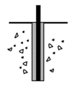
Downward installations (Figure 1) have historically presented relatively few challenges for adhesive injection in this regard. In such applications, gravity is helpful; the adhesive naturally flows to the bottom of the drilled hole while being dispensed from the cartridge through a static mixing nozzle. The installer maintains the open end of the nozzle below the free surface of the adhesive until the drilled hole is filled to the desired level. For deep holes, extension tubing is affixed to the open end of the nozzle to increase reach. This procedure avoids entrapping air bubbles in the adhesive material.
Installations into horizontal, upwardly inclined or overhead drilled holes (Figure 2) require more care on the part of adhesive anchor installers. Although the installation principle to avoid entrapping air is similar for these orientations, a key difference is that gravity does not help to keep the adhesive towards the “bottom” (deepest point) of the drilled hole. At worst, it can work against the installer when ambient temperatures may cause the adhesive to run out of the hole during injection. These adhesive anchor installations can be more difficult for an untrained installer and can slow the rate of work. This is one of the reasons that ACI 318-11 Section D.9.2.4 requires continuous special inspection of adhesive anchor installations in these three orientations when the application is also intended to resist sustained loads.

(Source: ACI 318-11, Section RD.1)
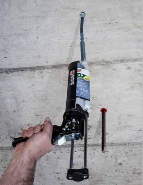
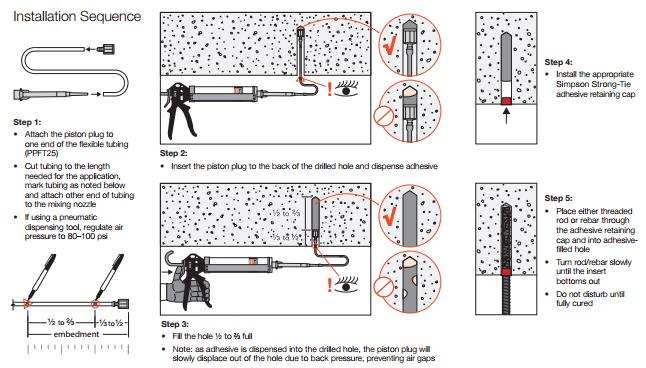
To aid the installer, Simpson Strong-Tie offers a piston plug adhesive delivery system (Figure 3). Consisting of pre-packaged flexible tubing, piston plugs and an adhesive retaining cap, this system allows installers to more easily and consistently make high-quality installations while completing their work efficiently. The installation sequence is provided in Figure 4.
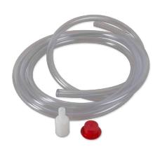
The system consists of three components:
- Piston plug – The key component of the system, it is slightly smaller in diameter than the drilled hole. As the adhesive is dispensed into the drilled hole, the piston plug is displaced out of the hole by the advancing volume of the injected adhesive. The displacement creates a more positive feel for the installer to know where the free surface of the adhesive is.
- Flexible tubing – For use with the piston plug to facilitate injection at the deepest point of the drilled hole.
- Adhesive retaining cap – Provided to prevent adhesive material from flowing out of the drilled hole after dispensing and to provide a centering mechanism for the insert. For heavy inserts in overhead conditions, other means must be provided to carry the weight of the insert and prevent it from falling or becoming dislodged from the hole before the adhesive has fully cured.
What do you think about the piston plug adhesive delivery system? Let us know by posting a comment below.
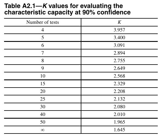
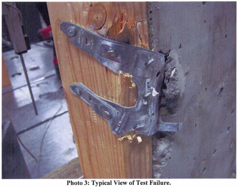
Anchor Testing for Light-Frame Construction
I started off doing a four-part series on how connectors, fasteners, concrete anchors and cold-formed steel products are tested and load rated. I realized that holdown testing and evaluation is quite a bit different than wood connector testing, so there was an additional post on holdowns. We have done several posts on concrete anchor testing (here and here), but I realize I never did a proper post about how we test and load rate concrete products per ICC-ES AC398 and AC399.
AC398 – Cast-in-place Cold-formed Steel Connectors in Concrete for Light-frame Construction and AC399 – Cast-in-place Proprietary Bolts in concrete for Light-frame Construction are two acceptance criteria related to cast-in-place concrete products.
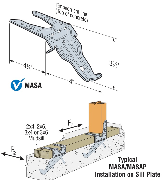
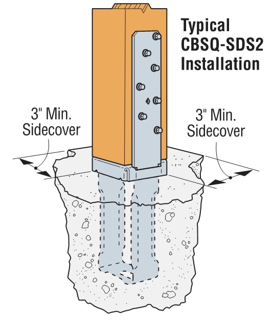
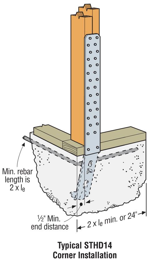
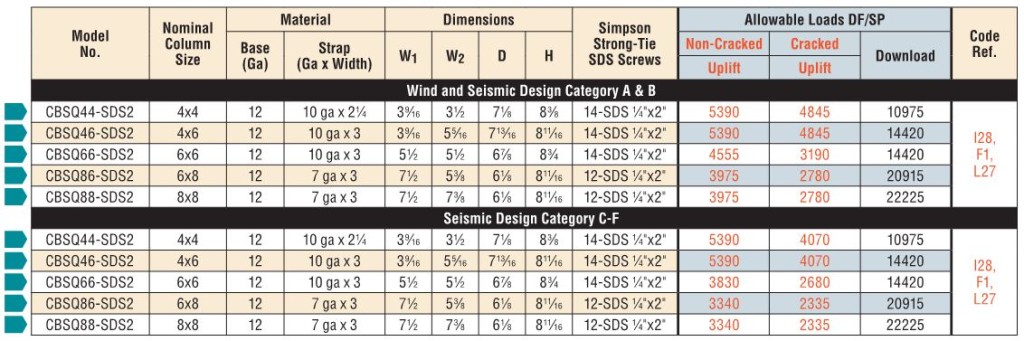
Cold-formed steel connectors embedded in concrete are not considered in ACI 318 Appendix D, so it was necessary to create criteria for evaluating those types of connectors. Some examples of products covered by AC398 are the MASA mudsill anchor, CBSQ post base, and the STHD holdown.
ACI 318 Appendix D addresses the design of cast-in-place anchors. However, the design methodology is limited to several standard bolt types.
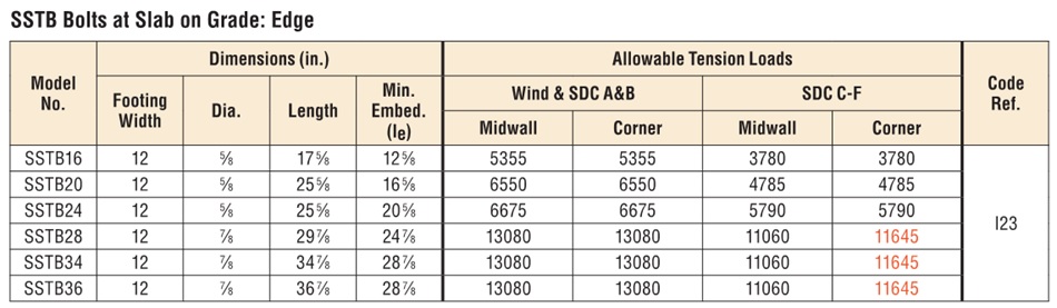
There are a number of anchor bolt products that have proprietary features that fall outside the scope of ACI 318, so AC399 fills in that gap by establishing test procedures to evaluate cast-in-place specialty anchors. Simpson Strong-Tie SB and SSTB anchor bolts are two families of anchors we have tested in accordance with AC399.
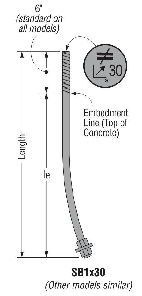
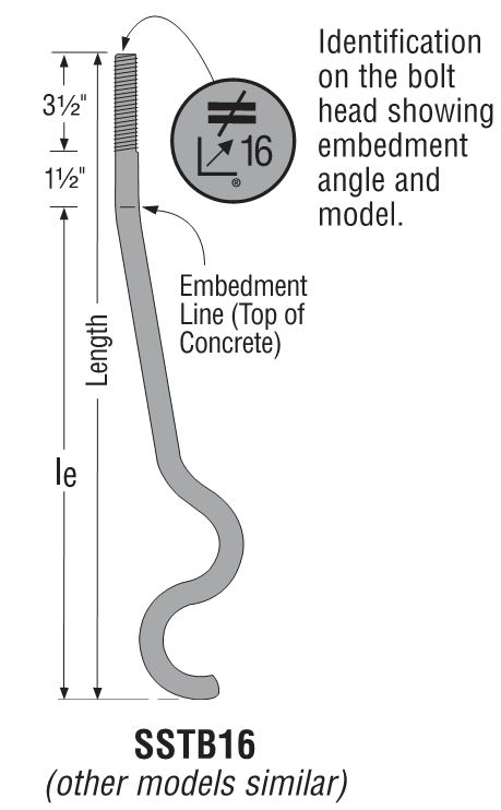
SB and SSTB anchors have a sweep geometry which increases the concrete cover at the anchored end of the bolt, allowing them to achieve higher loads with a 1¾” edge distance. The SSTB is anchored with a double bend, whereas the SB utilizes a plate washer and double nut.
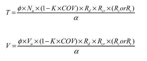
AC398 (concrete connectors) and AC399 (proprietary bolts) are similar in their test and evaluation methodology. AC398 addressing both tension and shear loads, whereas AC399 is limited to tension loads. Testing requires a minimum of 5 test specimens. These are the allowable load equations for AC398 and AC399:
For comparison, here is the standard AC13 allowable load equation for joist hangers:
Allowable Load = Lowest Ultimate / 3
Without getting into Greek letter overload, what are these terms doing?
Nu (or Vu) is the average maximum tested load. Calculating averages is something I actually remember from statistics class. Everything else I have to look up when we do these calculations.
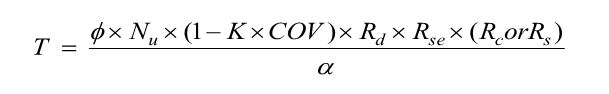
(1 – K x COV) uses K as a statistical one-sided tolerance factor used to establish the 5 percent fractile value with 90% confidence. This term is to ensure that 95% of the actual tested strengths will exceed the 5% fractile value with 90% confidence. COV is the coefficient of variation, which is a measure of how variable your test results are. For the same average ultimate load, a higher COV will result in a lower allowable load.
The K value is 3.4 for the minimum required 5 tests, and it reduces as you run more tests. As K decreases, the allowable load increases. In practice, we usually run 7 to 10 tests for each installation we are evaluating.
Rd is seismic reduction factor, 1.0 for seismic design category A or B, and 0.75 for all others. This is similar to what you would do in an Appendix D anchor calculation, where anchor capacities in higher seismic regions are reduced by 0.75.
Rs and Rc are reduction factors to account for the tested steel or concrete strength being higher than specified. There are some differences in how the two acceptance criteria apply these factors, which aren’t critical to this discussion. Φ is a strength reduction factor, which varies by failure mode and construction details. Brittle steel failure, ductile steel failure, concrete failure and the presence of supplemental reinforcement.
The α factor is used to convert LRFD values to ASD values. So α = 1.0 for LRFD and α = 1.4 for seismic and 1.6 for wind. Both criteria also allow you to calculate alpha based on a weighted average of your controlling load combinations. This has never made a lot of sense to me in practice. If you are going to work through the LRFD equations to get a different alpha value, you might as well do LRFD design.
Rse is a reduction factor for cyclic loading, which is applied to proprietary anchor bolts covered under AC399, such as the SSTB or SB anchors. A comparison of static load and cyclic load is required for qualification in Seismic Design Category C through F. Unlike the cracked reduction factor, manufacturers cannot take a default reduction if they want recognition for high seismic.
Due to the differences in AC398 and AC399 products, the load tables are a little different. AC398 products end up with 4 different loads – wind cracked, wind uncracked, seismic cracked and seismic uncracked.
AC399 products are a little simpler, having just wind and seismic values to deal with.
What are your thoughts? Let us know in the comments below.