In this post, we follow up on our October webinar, New Design Methods to Enclose Buildings Faster, by answering some of the interesting questions raised by attendees.
During the webinar, we discussed new design methods and solutions for curtain-wall and cladding connections and how they can maximize efficiency and resiliency throughout the construction process. In case you could not join our discussion, you can watch the on-demand webinar and earn PDH and CEU credits here.Continue Reading
In August 2012, Simpson Strong-Tie launched a comprehensive, innovative solution for curtain-wall framing. Our lead engineer for developing our line of connectors for curtain-wall construction explains the purpose of the curtain wall with the illustrations below.
First, curtain walls are not what you put up if you shared a room with your brother and sister when you were growing up. When I first learned about the use of cold-formed steel curtain walls, I laughed and thought: “Gosh, how useful this would be for someone growing up with 5 siblings in one bedroom!” I have always enjoyed the sense of humor that our engineers use to help explain technical topics.
Curtain walls can be described as exterior building walls with the primary purpose of protecting the interior building against the exterior weather and natural phenomena such as sun exposure, temperature changes, earthquakes, rain and wind.
To put it in structural terms, a curtain-wall system consists of non-load-bearing exterior walls that must still carry their own weight. Curtain walls are not part of the primary structural framing for the building, but they typically rely on the primary structural framing for support. Additionally, curtain walls receive wind and seismic loads and transfer these forces to the primary building structure.
Types of Curtain Walls
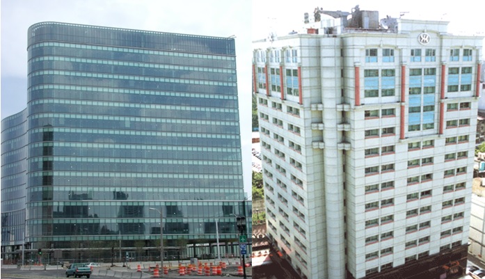
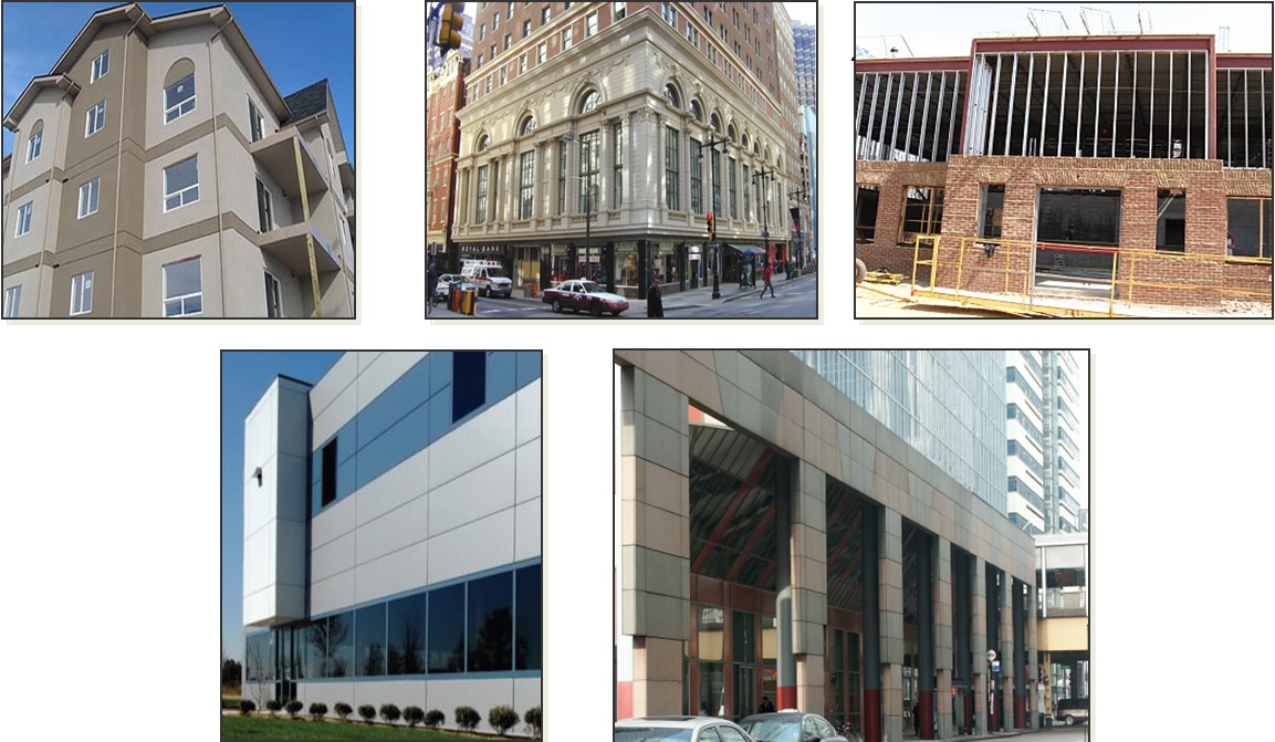
Glass and cladding curtain walls make up two basic types of curtain-wall systems. Glass curtain-wall systems are usually designed using aluminum-framed walls with in-fills of glass. The cladding curtain wall is a system with back-up framing that is covered in some type of cladding material. The cladding curtain-wall system is the type in which Simpson Strong-Tie products can be used.
The back-up framing is the structural element of the curtain-wall system. It is typically constructed with cold-formed steel studs ranging from 31/2″ to 8″ deep, in 33 mil (20 ga.) to 97 mil (12 ga.) steel thicknesses. The framing studs are typically spaced at 16″or 24″ on center. There are many different types of cladding materials. They include, but are not limited to, exterior insulation finish systems (EIFS), glass-fiber-reinforced concrete (GFRC), bricks, metal panels and stone panels.
Deflection
One essential function of the curtain wall is to allow for relative movement between the curtain-wall system and the main building structure. At first, it was not obvious to me why making this allowance was necessary, but our product development team creatively explained some of the reasons why this is an important must-have feature for curtain walls.
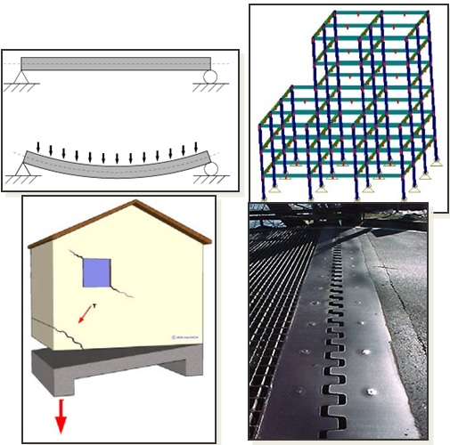
First, the primary building will move up and down as it is loaded and unloaded by the live-load occupancy, similar to beam live-load deflections.
Second, the structure sways and has torsional displacement due to movement from lateral wind or seismic loads.
Third, concrete structures typically encounter creep and shrinkage, and there may be foundation differential settlement or soil compression from high-gravity loads.
Lastly, the temperature differential may cause the building elements to expand and contract, which, again, can result in relative movement between structural elements. This is similar to a bridge’s steel plate expansion joint system.
And if you are a curious designer like me, you probably wonder why the relative vertical moment is so significant in engineering design.
One key reason is to ensure that the curtain walls do not collect gravity loads from the building, so as to prevent overloading and possible failure of the stud framing. In addition, a well-designed curtain-wall system needs to retain the primary structural load path as intended by the building designer.
The other reason is to protect the cladding of the building. If you remember earlier, the cladding material may be marble, granite or natural stones that are often very expensive and heavy. In some cases, the cladding can be one of the most expensive systems in a building. And there are times when it’s much more cost-effective to design for relative movement than it is to over-design structural framing to address the stringent deflection requirements.
Construction Type
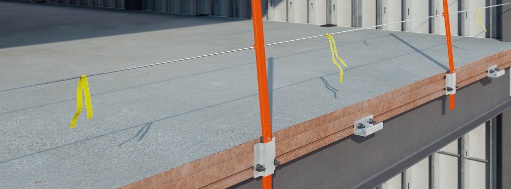
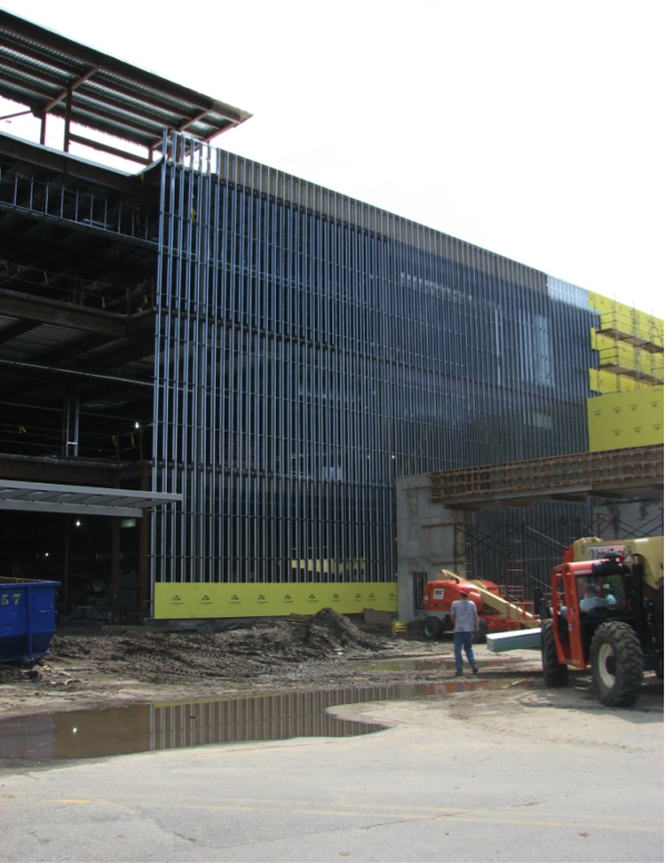
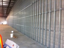
Bypass framing is a term that is often used in curtain-wall construction. In this system, the metal studs bypass the floor and hang off the outside edges of the building. You can see from the illustration how the studs run past, or bypass, the edge of the slab. In this case, the studs are supported vertically on the foundation at the bottom, and then run continuously past multiple floor levels.
Picture by Don Allen of Super Stud Building Products.
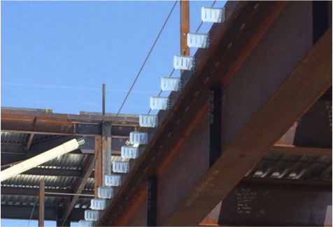
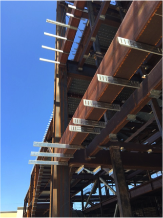
In steel construction, concrete fill over metal deck is typically constructed with a heavy-gauge bent plate or structural angle. Connectors can attach directly to the steel angle or the web of an edge beam.
It may seem that this type of construction is too complex and requires great efforts to detail the many connections needed to hang the curtain wall off the outside of the building. So what are the compelling reasons to choose bypass framing construction?
Bypass framing can accommodate flexibility for the architect. In another words, the bypass configuration easily allows architects to create reveals, set-backs and other architectural features. Plus, there are fewer joints to detail for movement when stud length can run continuously for several floors. Another benefit is that the exterior finish can also be installed on a curtain-wall system with a tighter tolerance than the edge of the structure.
One other special bypass framing type is known as ribbon window or spandrel framing. Ribbon windows are a series of windows set side by side to form a continuous band horizontally across a façade. The vertical deflection for this type of bypass framing is typically accommodated at the window head. This type of bypass usually works well for panelized construction.
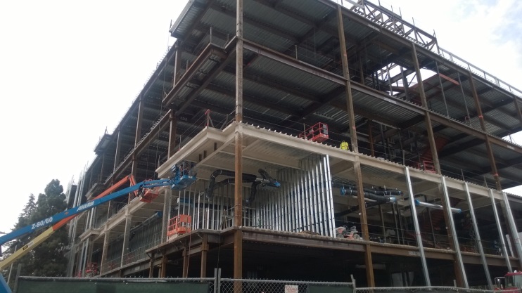
Another common curtain-wall system is infill framing, where the studs run from the top of one floor to the underside of the floor above. Sometimes it’s a challenge to attach bypass framing to the edge of thin concrete slabs. In the following illustration, deflection is designed at the top track of wall panels.
In Part 2 of this blog post series, I will provide more details about how we have innovated products to be used for this application, plus a more comprehensive post about the products we offer and how they are typically used.
I would like to invite you to comment and provide feedback on this topic and tell us whether you’ve had any experience working with a Designer on a CFS curtain-wall project. If you are a Designer who specializes in this discipline, how are you designing curtain-wall systems for seismic forces?
Did you know that Simpson Strong-Tie is celebrating its 60th birthday this year? We started out with one punch press and the ability to bend light-gauge steel. Then, one Sunday evening in the summer of 1956, Barclay Simpson’s doorbell rang and a request for our first joist hanger led us into the wood connector business. Since then, we’ve continued to grow that business by focusing on our engineering, research and development efforts. Some might say that nowadays we’re an engineering company that also happens to manufacture products, as evidenced by our focus on developing technology tools over the past few years such as web calculators, an updated website and design software. Our focus on technology, however, is really another aspect of our continued commitment to excellence in manufacturing and our application of the tenets of lean manufacturing.
Many of you may already be familiar with the idea of lean manufacturing made famous by Toyota in the early 2000s, along with the principles of continual improvement and respect for people. The concept of continual improvement is based on the idea that you can always make small changes to improve your processes and products. Although they were established in a manufacturing setting, these ideals ring very true for engineering as well; eliminate steps in your design process that don’t add any value to the final project and always be on the lookout for tools or techniques that can speed up your process. Thinking lean isn’t about cutting corners to get your result faster, it’s about mindfully getting rid of the steps that aren’t helping you and finding better ways of doing everyday tasks.
As structural engineers, we can find ourselves working on a variety of projects that lead us to perform repetitive calculations to check different conditions, such as varying parapet heights on the exterior of a building, or we may find ourselves working with an unfamiliar material, such as light-gauge or cold-formed steel (CFS), where we have to take some time away from design to review reference materials such as AISI S200-12 North American Standard for Cold-Formed Steel Framing. Wouldn’t it be great if there were a design tool that could help you complete your light-gauge projects more quickly, in complete compliance with current building codes?
It turns out that Simpson Strong-Tie offers a design tool called CFS Designer™ to help structural engineers improve their project design flow. This program gives engineers the ability to design light-gauge stud and track members with complex beam loading and span conditions according to building code specifications. What does that actually mean, though? Allow me to illustrate with an example of a design project.
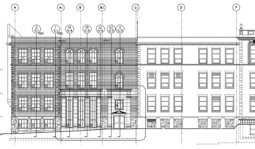
Let’s say you’re designing a building and part of your scope is the exterior wall framing, or “skin” of the building. You probably get sent some architectural plans that look something like this:
Figure 1. Sample building elevation with section marks.
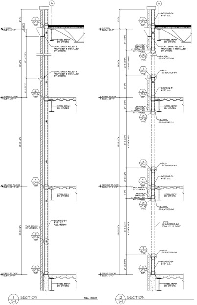
The architectural elevations will have wall section marks indicated for different framing situations. Two sample wall sections are shown in Figure 2.
Figure 2. Sample building wall sections.
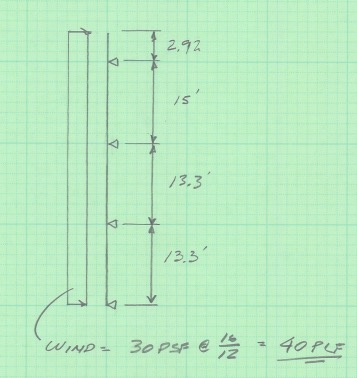
This building has several different wall section types that include door and window locations, varying parapet heights, diverse finish materials that need to meet different deflection criteria, and different connection points back to the base building. The traditional design calculation that you would need to run for one wall section might begin with a loading diagram similar to Figure 3 below.
Figure 3. Sample calculation of wall stud loading diagram.
Once you have your loading diagram generated, you would need to use reference load tables or a computer analysis program to solve for the axial and moment demands, the reactions at the pinned supports, and the member deflections.
After you determine the demand loads, you would then need to select a CFS member with sufficient properties, and you may need to iterate a few times to find a solution that meets the load and deflection parameters. After you’ve selected a member with the right width, gauge and steel strength, you’ll need to select an angle clip that can handle the demand loads, as well as fasteners to connect the clip to the CFS stud and to the base building. You would also need to also check the member design to ensure that it complies with bridging or bracing requirements per AISI. Then, after all that, you’d have to repeat the process again for all of the wall section types for your project.
Figure 4. Hmm, CFS design would sure be a lot easier if buildings were just huge windowless boxes…
Just writing out that whole process took some time, and you can imagine that actually running the calculations takes quite a bit longer. I think we can all agree that the design process we’ve outlined is time-consuming, and here’s where using CFS Designer™ to streamline your design process can really help.
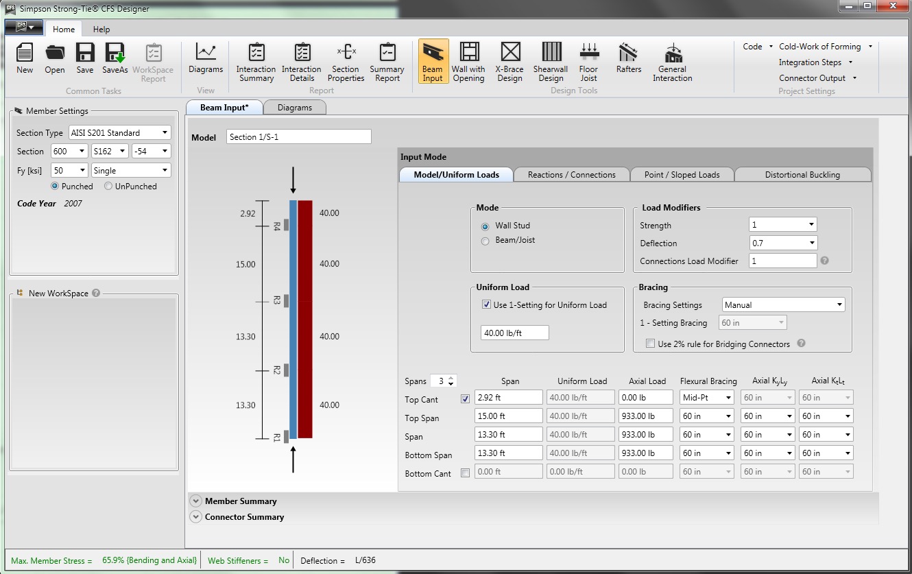
CFS Designer is a structural engineering design program that can automate many of the manual steps that are required in the design process. It has an easy-to-understand graphical user interface that allows you to input your project parameters within a variety of design modules from walls and beams, jambs and headers, X-brace walls, shearwalls, floor joists, and roof rafters. The program also enables the design of single stud or track members, built-up box-sections, back-to-back sections, and nested stud or track sections. Figure 5 shows an example of how you would input the same stud we looked at before into the program.
Figure 5. CFS Designer™ user interface for wall stud design.
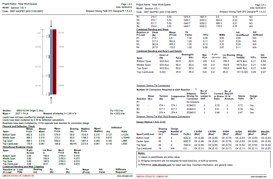
The program will generate the loading diagrams and complete calculation package for all of these different situations. And along with checking the member properties and deflection limits, CFS Designer will also check bridging and bracing requirements and provide connector solutions for the studs using tested and code-listed Simpson Strong-Tie products. Figure 6 shows an example of the summary output you would receive.
Figure 6. The comprehensive summary output page that covers the complete member design down to the bracing and connection solutions.
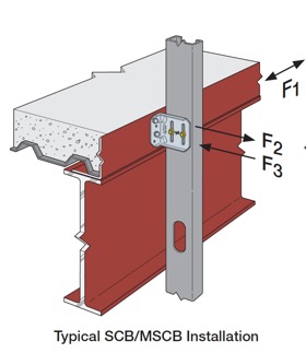
One unique part of the output is toward the center of the second page, under the heading “Simpson Strong-Tie Connectors.” This section summarizes the tension and compression loads at each reaction point and then shows a connector solution (such as the SCB45.5) along with the number of screws to the stud and the number of #12 sheet-metal screws to anchor back to the base building. Simpson Strong-Tie has developed and tested a full array of connectors specifically for CFS curtain-wall construction as well as for interior tenant improvement framing, which allows designers to select a connection clip straight out of a catalog without needing to calculate their own designs per the code. It’s just another way we’re helping you to get a little leaner!
The last part of the output shown in Figure 6 is titled “Simpson Strong-Tie Wall Stud Bridging Connectors.” It checks the bridging and bracing requirements per AISI S100 and selects a SUBH bridging connector, an innovative bridging solution developed by Simpson Strong-Tie that snaps into place and achieves design loads while only requiring one #10 screw to connect for 75% of applications.
Figure 8. A close-up of the SUBH installed (left) and a wall of studs with bridging installed using the LSUBH clips (right).
You can download a free trial of CFS Designer™ and give it a test drive to see how much time it can save you on a design project. The trial version has almost full functionality, with the exception of not being able to print the output sheets. You can see purchasing information online, and you should always feel free to contact your local Simpson Strong-Tie engineering department with any questions you may have. I hope you are able to take advantage of this great tool to further improve your everyday design processes. We will be sure to keep you updated on our latest technology tools that help speed up the design process. If you’re using CFS Designer, we’d like to hear your thoughts about the program. Please share them in the comments below.
“One test result is worth one thousand expert opinions.”
– Wernher von Braun
While reviewing some of our first catalogs, I was curious about the testing we did on those iconic products that launched our company. I found a test report from December 20, 1957 on crinkled yellow paper with a short description: U-29 Download Test. The signature from the independent testing agency was a little faded, and the data was typed by hand in a table. But I was thrilled to discover that our 1957 customers received exactly the same thing as our modern-day customers – the confidence in knowing that our allowable loads are supported by physical testing.
There simply is no substitute for a physical test.
For the first half-dozen years of my professional career, my experience with cold-formed steel (CFS) consisted of sizing studs for non-structural walls and red-marking the bracing details on architectural plans. When the dotcom bubble burst, my firm needed to shift its focus from high-tech commercial and industrial to more multifamily design work. Several developers we worked with built with CFS, so in addition to designing condominiums instead of cleanrooms, I was designing CFS.
Less than 10% of engineers have any exposure to CFS design as part of their undergraduate education. OK – so this is based on an informal survey of about 50 colleagues, but I suspect if I were to hire a market research firm for lots of money, I’d pretty much get the same response.
We use cookies on this site to enhance your user experience. By clicking "I AGREE" below, you are giving your consent for us to set cookies. Privacy PolicyI AGREE
Privacy & Cookies Policy
Privacy Overview
This website uses cookies to improve your experience while you navigate through the website. Out of these cookies, the cookies that are categorized as necessary are stored on your browser as they are essential for the working of basic functionalities of the website. We also use third-party cookies that help us analyze and understand how you use this website. These cookies will be stored in your browser only with your consent. You also have the option to opt-out of these cookies. But opting out of some of these cookies may have an effect on your browsing experience.
Necessary cookies are absolutely essential for the website to function properly. This category only includes cookies that ensures basic functionalities and security features of the website. These cookies do not store any personal information.
Any cookies that may not be particularly necessary for the website to function and is used specifically to collect user personal data via analytics, ads, other embedded contents are termed as non-necessary cookies. It is mandatory to procure user consent prior to running these cookies on your website.