

Continuous rod tiedowns are a common way to restrain shearwall overturning in light-frame structures. Anchoring the rod run in a steel beam can be challenging, however, because the holdown typically aligns with the beam’s web and thus cannot pass through the beam. Welding, on the other hand, can cause brittleness and fracture of the rod or coupler at the location of the weld, especially in high-strength steel rods and couplers. An effective alternative also using high-strength rods is provided by the Simpson Strong-Tie® ATS-SBC steel-beam connector, which comes with a steel plate whose flat edges can be fillet welded to the steel beam or embed plate without brittle failure. Scott Fischer, P.E., of Simpson Strong-Tie explains the results of our lab testing in the following post.
Continue Reading
Tag: holdowns
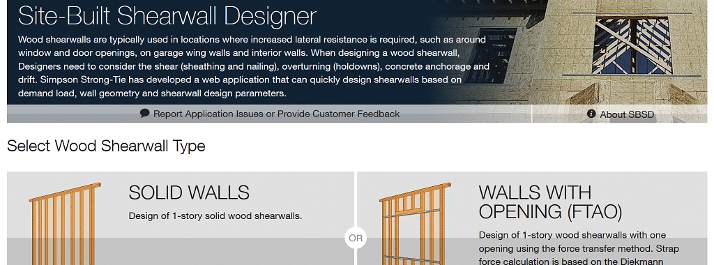
Introduction to the Site-Built Shearwall Designer Web Application
Wood shearwalls are typically used as a lateral-force-resisting system to counter the effects of lateral loads. Wood shearwalls need to be designed for shear forces (using sheathing and nailing), overturning (using holdowns), sliding (using anchorage to concrete) and drift, to list some of the main dangers. The Simpson Site-Built Shearwall Designer (SBSD) web app is a quick and easy tool to design a wood shearwall based on demand load, wall geometry and design parameters.Continue Reading
How to Pick a Connector Series – Selecting Fasteners
The parts won’t hold themselves up. They have to be fastened in place.
The previous blog in the How to Pick a Connector Series by Randy Shackelford, on “ Selecting a Joist Hanger,” covered the available Simpson Strong-Tie joist hanger options and how to pick a hanger for your design. This week’s blog focuses on the fasteners recommended for various wood connectors.
For straps, holdowns and other connectors, the first step is to specify a product that meets the load and corrosion resistance requirements. Then, specify fastening that is appropriate. The Wood Construction Connectors catalog, C-C-2015, offers fastener information for every Simpson Strong-Tie connector used in wood construction. If you specify the type and number of fasteners and install them as shown in the catalog, then your installation will get full design values. Many connectors are designed to be installed with either nails or Strong-Drive® SD Connector screws. Some products must be installed with Strong-Drive SDS Heavy-Duty Connector screws. Figure 1 is a snip from page 76 of catalog C-C-2015. Here the face-mount hanger table gives the size and number of nails to be installed in the header and the joist, and the table note defines the nail size terminology. Let’s take a look at the various fasteners used for Simpson Strong-Tie connectors of all varieties.
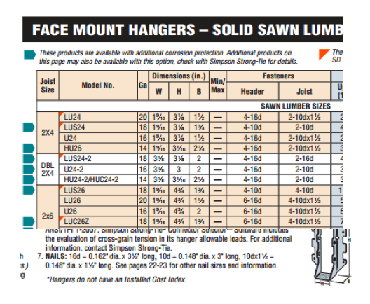
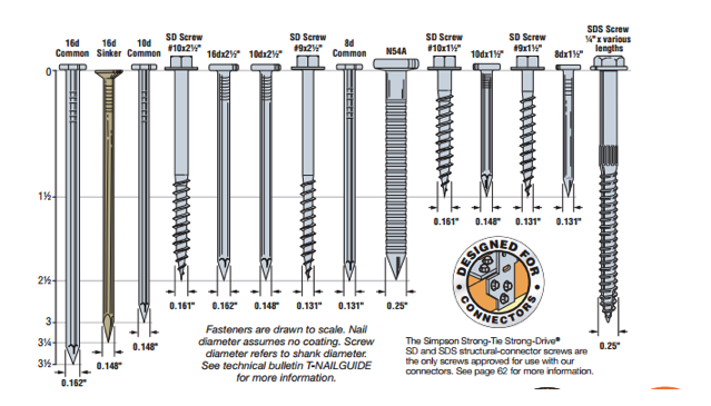
Figure 2 shows a scale view of almost all of the fasteners used with connectors. You can find this illustration in the Fastening Systems catalog, C-F-14, and the Wood Construction Connectors catalog, C-C-2015. However, we are continually designing, evaluating and adding new fasteners to use with our connectors. Check our website for the latest and greatest.
Keep in mind some generalities that are to be considered in every connector fastener specification.
- Type and size – Be sure to specify the correct type of fastener and size; for nails, that means diameter and length.
- Do not mix fasteners – Do not combine nails and screws in the same connector unless specifically allowed to do so in the load table.
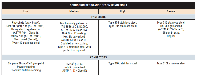
- Corrosion resistance – Consider environmental corrosion and galvanic corrosion. For environmental corrosion, specify fasteners that have corrosion resistance similar to the connector; for galvanic corrosion, the fasteners and connector should be galvanically compatible. Figure 3 shows the corrosion resistance recommendations for fasteners and connectors.
NAILS
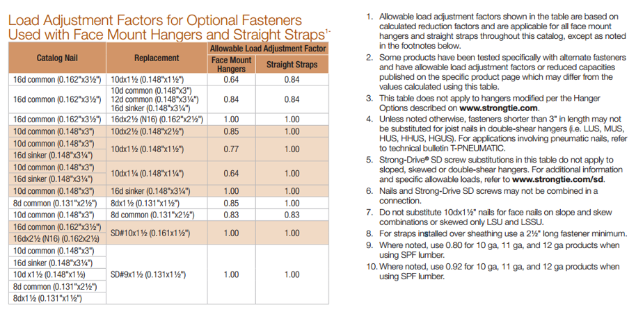
Nail terminology is messy. In a recent Structure Magazine article (July 2016), the author made the point that nail specifications are frequently misinterpreted (or overlooked), and as a result the built system does not have the intended design capacity. In general construction vernacular, specification by penny size identifies only the length. For example, a “10d” specification could be interpreted to mean 10d common – 0.148″ x 3″, 10d box – 0.128″ x 3″, 10d sinker – 0.120″ x 2.875″, or the 10d x 2.5″ – 0.148″ x 2.5″. See NDS-12, Appendix L, Table L4 for the length, nail diameter and head diameter of Common, Box, and Sinker steel wire nails. What if the face-mount hanger needed 0.148”x3” nails to achieve full load, but the face-mount hanger was installed with 0.148″ x2.5″? In this case, the nail substitution causes a reduction in load capacity of 15%. The load capacity losses would be even greater if 10d sinker or 10d box nails were used. The load adjustment factors for nail substitutions used with face- mount hangers and straight straps are shown in Table 3.
Simpson Strong-Tie nail terminology further complicates nail specification because, in Strong-Tie lingo, the penny reference is to diameter (not to length). This is further reason to write nail specifications in terms of diameter and length.
The best way to prevent mistakes is to specify nails by both length AND diameter.
There are two types of connector nails available, the Strong-Drive® SCNR Ring-Shank Connector nail and the Strong-Drive SCN Smooth-Shank Connector nail. SCN stands for Structural Connector Nails. R would refer to ring- shank nails. Currently most ring-shank connector nails are available in Type 316 stainless steel. Reasons for this are discussed here. The smooth-shank nails are made of carbon steel and either have a hot-dip galvanized (HDG) finish meeting the specifications of ASTM A153, Class D, or have a bright finish. Stainless-steel ring-shank nails are recommended for stainless-steel connectors. Use hot-dip galvanized nails with ZMAX® and HDG connectors. See Table 1 for the nail properties.
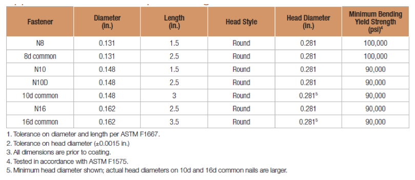
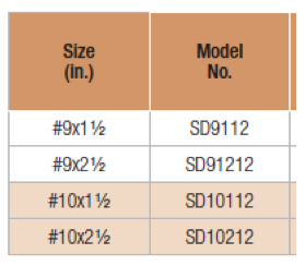
Simpson Strong-Tie connector nail specifications include common nails, sinker nails and short nails. Nails used in connectors should always have a full round head and meet the bending yield requirements of ASTM F1667, Table S1. Nails can be driven with a hammer or power-driven. Table 2 shows the Strong-Tie connector nails by catalog name, size and model number.

Remember that connector double-shear nailing should always use full-length common nails. Do not use shorter nails in double-shear conditions.
Table 3 is snipped from the Fastening Systems catalog, and it shows load adjustment factors for optional fasteners used in face-mount hangers and straps.
SD Screws
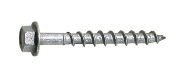
Almost 150 Simpson Strong-Tie connectors can be installed with Simpson Strong-Tie Strong-Drive® SD Connector screws (Figure 4). The shanks of the SD Connector screws are designed to match the fastener holes in Simpson Strong-tie connectors. The screw features, dimensions, strengths and allowable single-fastener properties are given in ICC-ES ESR-3046, and the SD screws have been qualified for use in engineered wood products. See ICC-ES ESR-3096 for code-approved connectors installed with SD screws.
SD screws can make connector and strap installation easier and can also provide some resistance that is needed beyond what might be offered by nails. Ease of installation is sometimes an issue in tight places where it might be much easier to use a screw-driving tool rather than a hammer or a power nailer. Some installations are improved by using screws instead of nails, especially where pulling away from the mounting member is a possible failure mode. For example, joist hangers for a deck need withdrawal resistance to help keep the deck tightly connected to the ledger.
SD screws are available in four sizes as shown in Table 4 below. These screws are mechanically galvanized per ASTM B695, Class 55, and have corrosion-resistance qualifications for use in chemically treated wood for Exposure Conditions 1 and 3 per ICC-ES AC257, which is the acceptance criterion for Corrosion-Resistant Fasteners and Evaluation of Corrosion Effects of Wood Treatment Chemicals. See ICC-ES ESR-3046 for corrosion resistance details. Visit SD Screws in Connectors for a complete list of connectors that can be installed with SD screws.
Here are a few specification and construction tips for SD screws:
- SD10 screws replace 16d common and N16 nails in face-mount hangers and straps.
- SD9 screws replace 8d and 10d common and 1-1/2″ size nails and 16d sinker nails (all nails 0.148″ and 0.131″ diameter) in face-mount hangers and straps.
- When SD screws are to be an alternative to nails, specify and use only SD screws. Other types of screws shall not be substituted.
- SD screws are required to be installed by turning. Do not drive them with a hammer or palm nailer!
- SD screws and nails cannot be mixed in the same connector.
SDS Screws
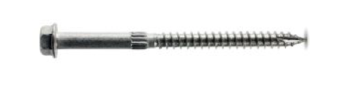
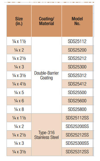
The Simpson Strong-Tie Strong Drive® SDS Heavy-Duty Connector screws are 1/4″ screws with a hex washer head (Figure 5). They are available in nine lengths. Table 5 shows the available SDS screws. SDS Screws are available with a double-barrier coating or in Type 316 stainless steel. These screws can be installed with no predrilling and have been extensively tested in various applications. SDS screws can be used for both interior and exterior applications. See ICC-ES ESR-2236 for dimensions, mechanical properties and single-fastener allowable properties. As shown in the evaluation report, SDS screws are also qualified for use in chemically treated wood. See the evaluation report for particulars. SDS screws also have been qualified for use in engineered wood products.
If you need more information about the nails and screws recommended for use with Simpson Strong-Tie connectors, visit strongtie.com and see the appropriate catalog, flier or engineering letter. Remember, your choice of fasteners affects the load capacity of your connections.
Let us know if you have any comments on Simpson Strong-Tie fasteners for straps, holdowns and other connectors.
Installation Errors – They Happen
A few years ago, we did a post on creative uses of our products. Most of the uses shown were artistic, or functional do-it-yourself projects, with one odd car spoiler modification. This week, I was reviewing some slides in a presentation that I give a few times a year regarding product installation errors. I call them misinstallations, but I’m not sure that’s a word. I thought I’d share a few of the more instructional ones. Most of the photos were curated by our northwestern region training manager, Olga Psomostithis – thanks Olga!
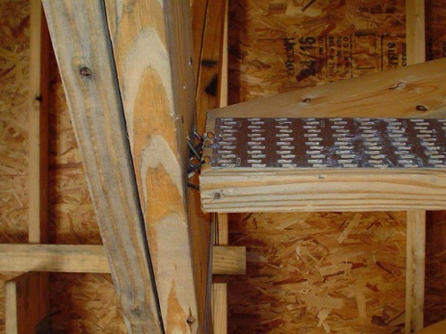
Double Shear Hangers
Double shear hangers require joist fasteners that are long enough to penetrate through the hanger, through the joist and into the header. The joist nails help transfer load from the joist into the header, resulting in higher allowable loads.
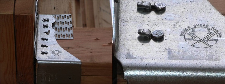
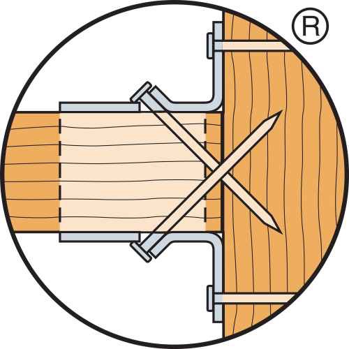
The installation shown has had the double shear tabs bent back, and nails installed straight into the joist. Since the joist nails do not penetrate the header, this would result in a reduced capacity.
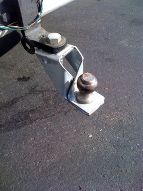
Holdowns
I’m including the trailer hitch installation because it makes me laugh no matter how many times I see it.
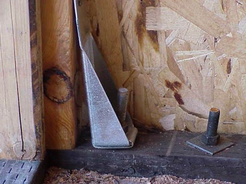
A very common question we get about holdowns is related to posts being offset too far from the anchor bolt (or is the anchor too far from the post?). In the installation shown below, the holdown is not flush with the post as the anchor bolt is offset about 1 inch. For small offsets up to about 1½”, a common solution is to raise the holdown off the sill plate and extend the anchor bolt with a coupler and bend it so there is a small (1:12) slope to it.
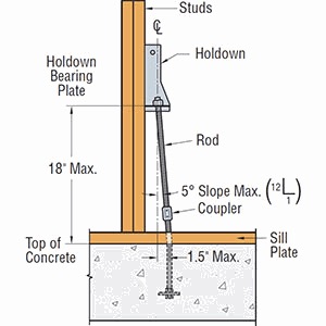
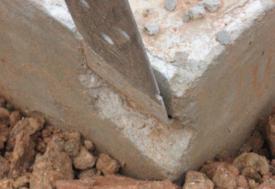
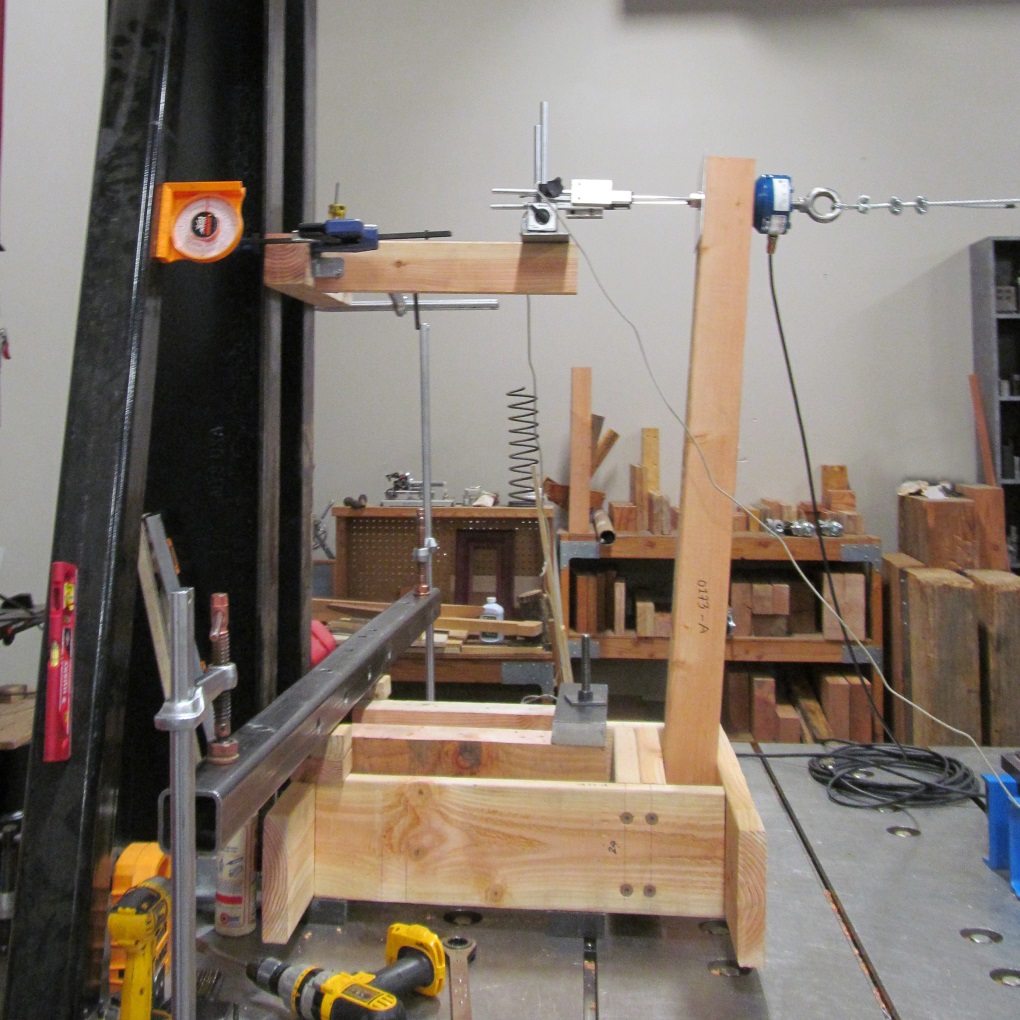
The holdown test standard, ICC-ES AC155, which is discussed in this post, requires that holdowns are tested raised off the test bed, which you can see in the photo below. Holdowns may be raised up to 18” above the top of concrete without a reduction in load provided that the additional elongation of the anchor rod is accounted for.
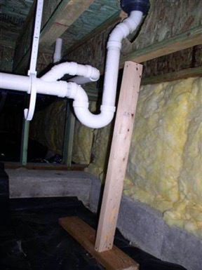
I like this photo because the installer put on the nail stops to protect the pipes. It is good to remember that plumbing happens when laying out a structural system.
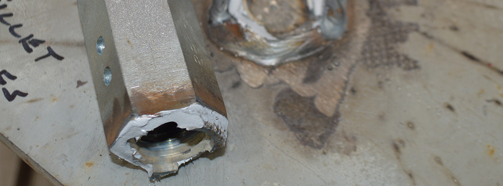
 STHD Holdowns
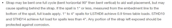
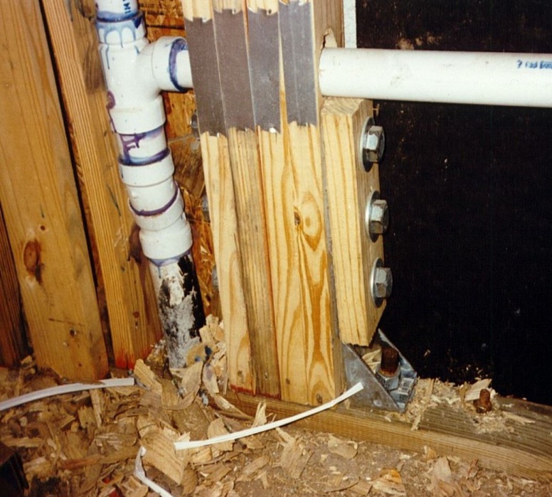
The photo above is not a misinstallation, but something that can happen. Embedded strap-style holdowns are cost-effective solutions for shearwall overturning or wind uplift. It is permitted to bend the straps to horizontal and back to vertical one cycle. If spalls form, they should be evaluated for reduced loads. Any portion of the strap left exposed should be protected against corrosion.
Hanger Gaps
Gaps can occur between trusses and supporting girders for a variety of reasons. For standard hanger tests, a 1/8″ gap is required between the joist and header per ASTM D7147. A resource for evaluating conditions with larger gaps is our technical bulletin Allowable Loads for Joist Hangers with Gaps. The technical bulletin has load data for a variety of hangers with gaps up to 3/8″, as well as recommended repairs for larger gaps. Our HTU product series comprises truss hangers specifically engineered to allow gaps up to ½”.

After going through a design project and carefully selecting the members and details of construction, it can be frustrating as an engineer to get that phone call from the general contractor or building inspector informing you that something is not right with the construction. Understanding some of the resources available to address installation errors can help solve these problems more quickly, and get you back to designing the next project.
Wood-framed Deck Guard Post Resources and Residential Details
A deck and porch study reported that 33% of deck failure-related injuries over the 5-year study period were attributed to guard or railing failures. While the importance of a deck guard is widely known, there was a significant omission from my May 2014 post on Wood-framed Deck Design Resources for Engineers regarding the design of deck guards.
A good starting point for information about wood-framed guard posts is a two-part article published in the October 2014 and January 2015 issues of Civil + Structural Engineer magazine. “Building Strong Guards, Part 1” provides an overview of typical wood-framed decks, the related code requirements and several examples that aim to demonstrate code-compliance through an analysis approach. The article discusses the difficulties in making an adequate connection at the bottom of a guard post, which involve countering the moment generated by the live load being applied at the top of the post. Other connections in a typical guard are not as difficult to design through analysis. This is due to common component geometries resulting in the rails and balusters/in-fill being simple-supported rather than cantilevered. “Building Strong Guards, Part 2” provides information on the testing approach to demonstrate code-compliance. Information about code requirements and testing criteria are included in the article as well.
Research and commentary from Virginia Tech on the performance of several tested guard post details for residential applications (36” guard height above decking) is featured in an article titled “Tested Guardrail Post Connections for Residential Decks” in the July 2007 issue of Structure magazine. Research showed that the common construction practice of attaching a 4×4 guard post to a 2x band joist with either ½” diameter lag screws or bolts, fell significantly below the 500 pound horizontal load target due to inadequate load transfer from the band joist into the surrounding deck floor framing. Ultimately, the research found that anchoring the post with a holdown installed horizontally provided enough leverage to meet the target load. The article also discussed the importance of testing to 500 pounds (which provides a safety factor of 2.5 over the 200-pound code live load), and the testing with a horizontal outward load to represent the worst-case safety scenario of a person falling away from the deck surface.
Simpson Strong-Tie has tested several connection options for a guard post at the typical 36” height, subjected to a horizontal outward load. Holdown solutions are included in our T-GRDRLPST10 technical bulletin. In response to recent industry interest, guard post details utilizing blocking and Strong-Drive® SDWS TIMBER screws have been developed (see picture below for a test view) and recently released in the engineering letter L-F-SDWSGRD15. The number of screws and the blocking shown are a reflection of the issue previously identified by the Virginia Tech researchers – an adequate load path must be provided to have sufficient support.
Have you found any other resources that have been helpful in your guard post designs? Let us know by posting a comment.
Holdown Anchorage Solutions
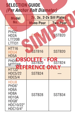
A common question we get from specifiers is “What anchor do I use with each holdown?” Prior to the adoption of ACI 318 Appendix D, this was somewhat simple to do. We had a very small table near the holdown section of our catalog that listed which SSTB anchor worked with each holdown.
During the good old days, anchor bolts had one capacity and concrete wasn’t cracked. ACI 318 Appendix D gives us reduced capacities in many situations, different design loads for seismic or wind and reductions for cracked concrete. These changes have combined to make anchor bolt design more challenging than it was under the 1997 Uniform Building Code.
This blog has had several posts related to holdowns. So, What’s Behind a Structural Connector’s Allowable Load? (Holdown Edition) explained how holdowns are tested and load rated in accordance with ICC-ES Acceptance Criteria. Damon Ho did a post, Use of Holdowns During Shearwall Assembly, which discussed the performance differences of shearwalls with and without holdowns, and Shane Vilasineekul did a Wood Shearwall Design Example. So I won’t get in to how to pick a holdown.
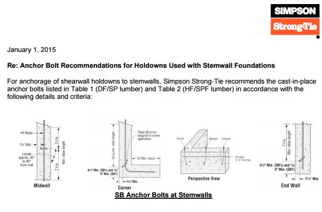
Once you have determined your uplift requirements and selected a post size and holdown, it is necessary to provide an anchor to the foundation. To help Designers select an anchor that works for a given holdown, we have created different tables that provide anchorage solutions for Simpson Strong-Tie holdowns.
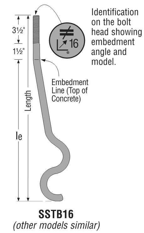
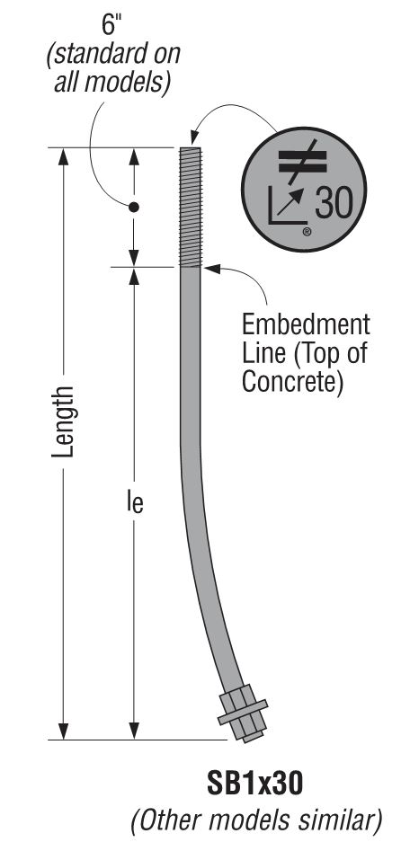
There is one Engineering letter that addresses slab-on-grade foundations and another version that covers stemwall foundations. The tables are separated by wood species (DF/SP and SPF/HF) to give the most economical anchor design for each post material. The preferred anchor solutions are SSTB or SB anchors, as these proprietary anchor bolts are tested and will require the least amount of concrete. When SSTB or SB anchors do not have adequate capacity, we have tabulated solutions for the PAB anchors, which are pre-assembled anchors that are calculated in accordance with ACI 318 Appendix D.
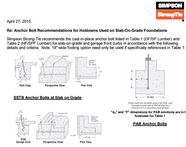
The solutions in the letters are designed to match the capacity of the holdowns, which allows the contractor to select an anchor bolt if the engineer doesn’t specify one. They are primarily used by engineers who don’t want to design an anchor or select one from our catalog tables. We received some feedback from customers who were frustrated that some of our heavier holdowns required such a large footing for the PAB anchors, whereas a slightly smaller holdown worked with an SB or SSTB anchor in a standard 12″ footing with a 1½” pop out.
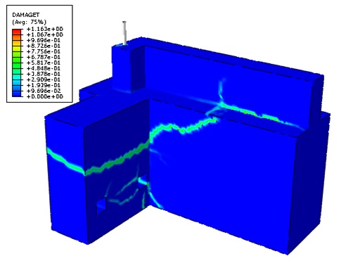
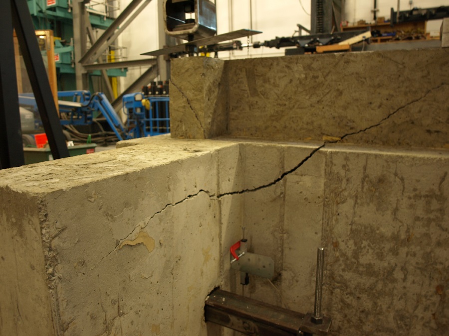
To achieve smaller footings using our SB1x30 anchor bolts, we reviewed our original testing and created finite element (FEA) models to determine what modifications to the slab-on-grade foundation details would meet our target loads. Of course, we ran physical tests to confirm the FEA models. With a 6″ pop out, we were able to achieve design loads for HD12, HDU14 and HHDQ14.
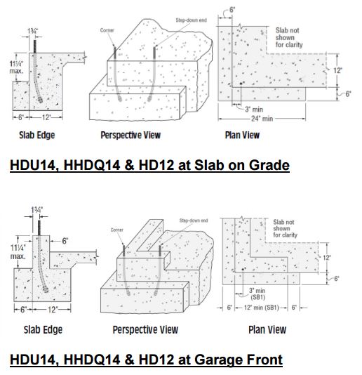
The revised footing solutions for the heavier holdowns require less excavation and less concrete than the previous Appendix D calculated solutions, reducing costs on the installation.
What has been your experience with holdown anchorage? Tell us in the comments below.
Use of Holdowns During Shearwall Assembly
When designing a shearwall according to the International Building Code (IBC), a holdown connector is used to resist the overturning moment due to lateral loading. From a structural statics point of view, a shearwall without dead load or holdowns would have zero lateral-resisting capacity without any restraint to resist the overturning moment. Since the wall assembly still has the sill plate anchorage providing resistance to overturning, testing can measure the capacity of a wall assembly without holdowns.
New Holdown Requirements for the IRC® and IBC® Portal Frame Bracing Method
The IRC® contains several different narrow bracing methods that are made up of portal frames. One method that is useful if you are using intermittent wall bracing is the Method PFH Portal Frame with Holdowns. This method relies on low-deflection holdown anchorage at the bottom, and substantial nailing at the overlap of the sheathing and the header at the top to prevent overturning of the narrow panel. An identical method for use as wall bracing is in the Conventional Construction section in Chapter 23 of the IBC®. These portal frames were first included in the 2006 IBC and IRC.
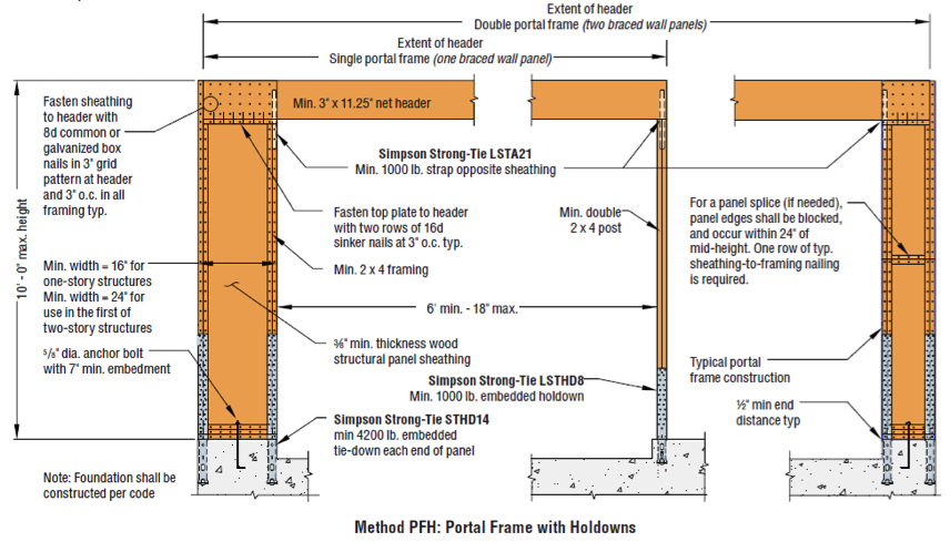
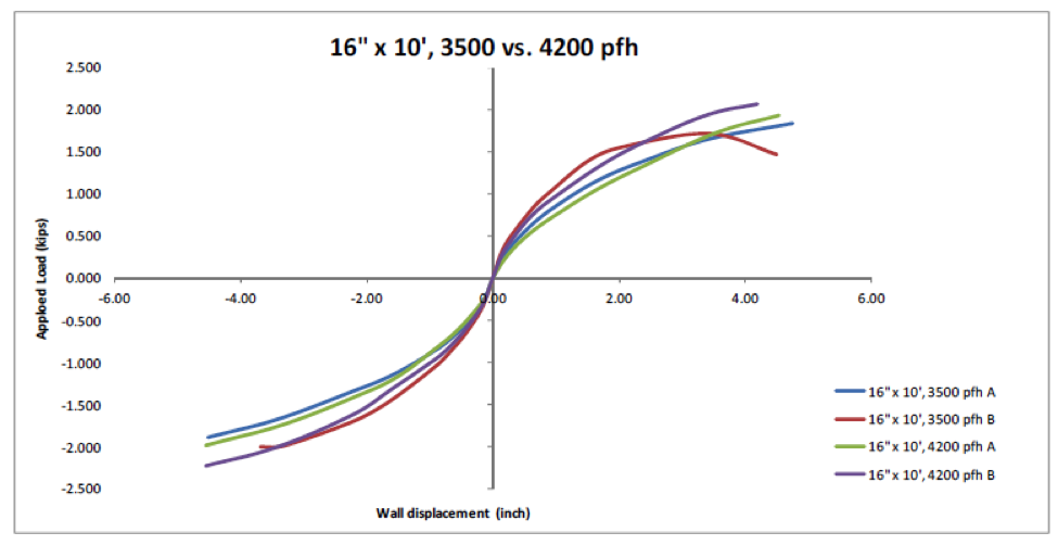
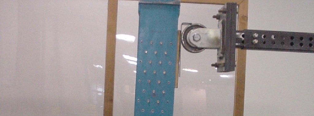
The method was originally tested with straps clamped to a steel test bed to simulate the embedded holdown straps. The straps were nailed to the wood with enough nails to mimic a 4,200 lb. strap anchor. The original test report is APA T2002-70. At that time, the Simpson Strong-Tie® STHD14 had a published allowable load in excess of 4,200 lbs. based on then-current Acceptance Criteria, so hardware was available to construct this frame throughout the country. However, in 2008, ICC Evaluation Service developed a new acceptance criteria for embedded connectors, AC398, Acceptance Criteria for Cast-in-place Cold-formed Steel Connectors in Concrete for Light-frame Construction. This was in response to the changes in ACI 318 for anchors in concrete. When re-tested and evaluated using the new Acceptance Criteria, the allowable load for STHD14 was reduced below 4,200 lbs. for use in buildings designed for Seismic Design Categories C through F. The same thing happened to other manufacturers’ embedded holdown allowable loads. That made it impossible to properly construct this bracing method in those areas. In response to this, Simpson Strong-Tie worked with APA, the Engineered Wood Association, to design a new test that would determine if a lower capacity holdown could be used with this portal frame method. APA performed the testing at their Tacoma, Washington testing lab. Since the initial testing of the portal frames with the 4,200 lb. holdown was performed using the outdated SEAOSC protocol with an older testing rig that used a stiff beam above the wall, both the old tests with a simulated 4,200 lb. holdown and new tests with a simulated 3,500 lb. holdown were rerun in accordance with the current ASTM E2126 test method using the CUREe protocol. The test was published as Test Report T2012L-24. The tests showed little to no effect of reducing the holdown from 4,200 lbs. to 3,500 lbs. allowable load. Here is one of the graphs of the backbone curves comparing the two assemblies for a 16-inch wide, 10-foot tall portal frame.
With the testing complete, APA prepared and submitted code changes to both the 2012 International Building Code® and 2012 International Residential Code®. The IBC proposal is S291-12, and can be found on page 605 of the 2012 Proposed Changes to the International Building Code – Structural. The IRC proposal is RB311-13, and can be found on page 613 of the 2013 Proposed Changes to the International Residential Code-Building. With support from Simpson Strong-Tie, both of the proposals were approved. So in the 2015 IRC, bracing method PFH will require an embedded strap-type holdown with a minimum capacity of 3,500 lbs. instead of 4,200 lbs. The same will hold true for the Alternate Braced Wall Panel Adjacent to a Door or Window Opening bracing method in the 2015 IBC. APA also re-tested the portal frames with only two sill plates instead of three. This will allow the use of a 5/8” by 8” Titen HD® anchor as a retrofit anchor bolt. What are your thoughts? Let us know in the comments below.
So, What’s Behind A Structural Connector’s Allowable Load? (Holdown Edition)
This is Part 1A of a four-part series I’ll be doing on how connectors, fasteners, anchors and cold-formed steel systems are load rated.
I envisioned doing a four-part series on how connectors, fasteners, anchors, and cold-formed steel are load rated. After writing the first installment on connectors, I realized that connectors are a bit more complicated, since the testing and evaluation for joist hangers (or similar devices) is different than testing for holdown devices. And I wanted to discuss holdowns. So without belaboring the apology for my numbering system, this will be part 1A of the series – still discussing wood connectors, but focusing on holdowns and some of the unique requirements in their load rating.Continue Reading
So, What's Behind A Structural Connector's Allowable Load? (Holdown Edition)
This is Part 1A of a four-part series I’ll be doing on how connectors, fasteners, anchors and cold-formed steel systems are load rated.
I envisioned doing a four-part series on how connectors, fasteners, anchors, and cold-formed steel are load rated. After writing the first installment on connectors, I realized that connectors are a bit more complicated, since the testing and evaluation for joist hangers (or similar devices) is different than testing for holdown devices. And I wanted to discuss holdowns. So without belaboring the apology for my numbering system, this will be part 1A of the series – still discussing wood connectors, but focusing on holdowns and some of the unique requirements in their load rating.
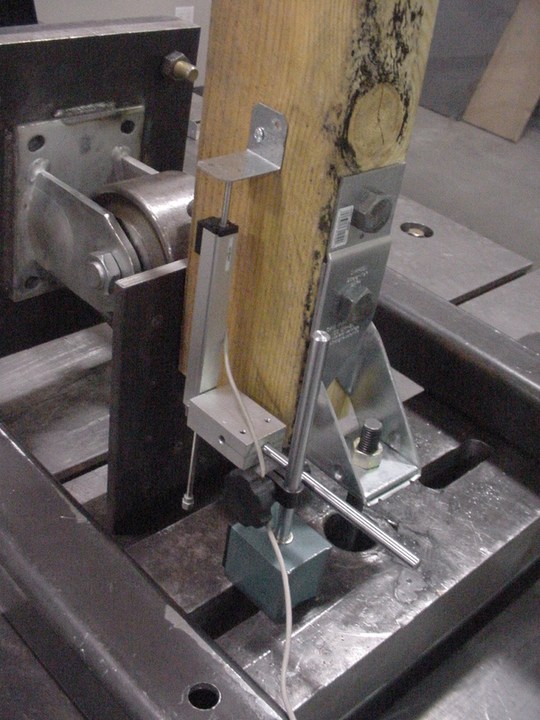
AC155, Acceptance Criteria for Hold-Downs (Tie-Downs) Attached to Wood Members, was first developed in 2005 to better address boundary conditions, deflection limits, and wood post limits. Prior to AC155, holdowns were evaluated based on testing on a steel jig with a safety factor of 3.0 and an NDS bolt calculation. Deflection at the allowable load was simply reported so that it was available for use in design, but there was not a deflection limit that affected the load rating.

In the steel jig setup shown, the jig keeps the holdowns stationary while the rectangular bar underneath the holdowns is pushed downward to simulate an uplift force. This was (and still is) an effective method of testing the capacity of the steel body of a holdown, but it does not tell you a lot about the deflection of the holdown when installed on a wood member. Since story-drift is such a critical component to shearwall performance and the deflection of holdowns has a significant effect on the total drift, this needed to be address in the holdown test standard.
Continue Reading