


Prior to joining Simpson Strong-Tie, I spent 13 years working as consulting structural engineer. As a specifier, I was amazed at the number of resources Simpson made available to me. From software, to blogs, to design guides, there were many resources to help me solve problems and streamline the design process. One resource that can sometimes be overlooked is the numerous engineering letters Simpson Strong-Tie engineers have authored to assist in the use of our products.
Tag: hurricane tie
The H1A Hurricane Tie – An Update for a Classic
Simpson Strong-Tie recently released an updated model of our H1 – now the H1A. As a consulting engineer, I remember how much I disliked updating my standard details when products were discontinued. I thought it would be informative to explain the modifications and some of the reasons for them.

What You Need to Know About Differences in Wind-Speed Reporting for Hurricanes
There is a great deal of good information out there to help us better understand hurricanes and their impact on people, structures and other property. To improve awareness of wind speeds and their measurement, this article will discuss a commonly misunderstood aspect of hurricane wind-speed reporting.
Continue Reading
How to Select a Connector – Hurricane Tie
When it comes to wood-frame construction, hurricane ties are among the most commonly specified connectors. They play a critical role in a structure’s continuous load path and may be used in a variety of applications, like attaching roof framing members to the supporting wall top plate(s), or tying wall top or bottom plates to the studs. They are most commonly used to resist uplift forces, but depending on regional design and construction practices, hurricane ties may also resist lateral loads that act in- or out-of-plane in relation to the wall.
Simpson Strong-Tie manufactures approximately 20 different models of hurricane ties, not counting twist straps, other clips, or the new fully-threaded SDWC screws often used in the same applications. This assortment of models raises the question, “How do you select the right one?”
In this post, we’ll outline some of the key elements to consider when selecting a hurricane tie for your project.
Demand Load
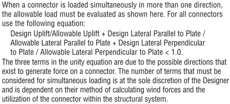
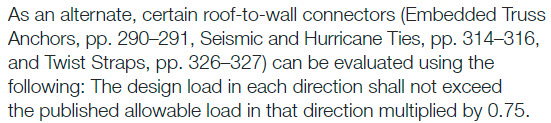
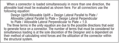
Let’s start with the obvious one. If your building’s roof trusses have an uplift of 600 lb. at each end, don’t select a hurricane tie with a published capacity of less than 600 lb. It’s also important to consider combined loading if you plan to use the tie to resist both uplift and lateral loads. When the connector is resisting lateral loads, its capacity to resist uplift is reduced. I won’t go into too much detail on this topic since it was covered in a recent blog post, but in lieu of the traditional unity equation shown in Figure 1, certain Simpson Strong-Tie connectors (hurricane ties included) are permitted to use the alternative approach outlined in Figure 2.
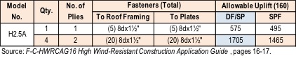
What if the tabulated loads in the catalog for a single connector just aren’t enough? Use multiple connectors! An important note on using multiple connectors, though: Using four hurricane ties doesn’t always mean you’ll get 4x the load. Check out the recently updated F-C-HWRCAG16 High Wind-Resistant Construction Application Guide for allowable loads using multiple connectors and for guidance on the proper placement of connectors so as to avoid potential overlap or fastener interference.
Dimensional Requirements
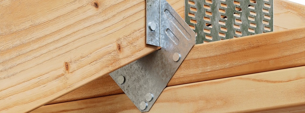
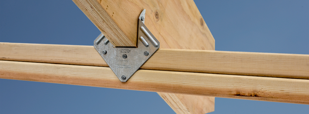
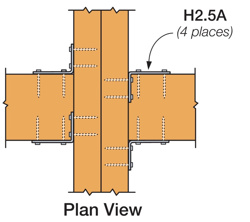
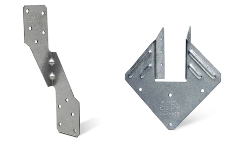
While the majority of the hurricane ties that Simpson Strong-Tie offers are one-sided (such as the H2.5A), some are designed so the truss or rafter fits inside a “U” shape design to allow for fastening from both sides (such as the H1). If using the latter, make sure the width of the truss or rafter is suitable for the width of the opening in the hurricane tie. For example, use our new H1.81Z (not the H1Z) for 1¾” wide engineered roof framing members.
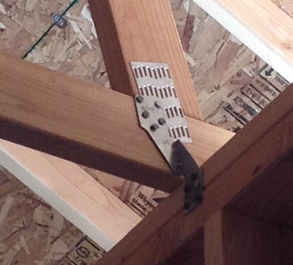
Additionally, the height of the hurricane tie and the wood members being attached should be compatible. For example, an H2.5A would not be compatible with a roof truss configured with only a nominal 2×4 bottom chord over the plate since the two upper nail holes in the H2.5A will miss the 2×4 bottom chord (see Figure 7). This is actually such a common mis-installation that we specifically tested this scenario and have developed an engineering letter on it (note the greatly reduced capacity). In this case the ideal choice would be the H2.5T, which has been specifically designed for a 2×4 truss bottom chord.

Fasteners with Hurricane Ties
It’s also essential to pay close attention to the diameter and length of the fasteners specified in the Simpson Strong-Tie literature. While many hurricane ties have been evaluated with 8d x 1½” nails for compatibility with nominal 2x roof framing, some require the use of a longer, 8d common (2½” long) nail and others require a larger-diameter 10d nail.
When specifying products for a continuous load path, it’s a good idea to select connectors that all use the same size nail to avoid improper installations on the job. It’s much easier if the installer doesn’t need to worry about which size nail he currently has loaded in his pneumatic nailer.
Wall Framing
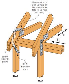
Do your roof and wall framing members line up? If so, creating a continuous load path can be made simpler by using a single hurricane tie to fasten the roof framing to studs. The H2A, H7Z, and H10S are some of the connectors designed to do just that. If your framing doesn’t align, though, you can use two connectors to complete the load path. For simplification and to reduce potential mix-ups in the field, consider selecting the same hurricane tie for your roof framing-to-top-plate and top plate-to-stud connections, like the H2.5A.
Besides the added benefit of fewer connectors to install, using a single hurricane tie from your roof framing to your wall studs can eliminate top-plate roll, a topic discussed at length in one of our technical bulletins.
Other Factors When Selecting Hurricane Ties
Some additional factors that may influence your selection of a hurricane tie are:
- Environmental factors and corrosion should be considered when selecting any product. Nearly every hurricane tie is available in ZMAX®, our heavier zinc galvanized coating, and several are available in Type 316 stainless steel. A full list of products available in ZMAX or stainless steel may be found on our website. On a related note, be sure to use a fastener with a finish similar to that of the hurricane tie in order to avoid galvanic corrosion caused by contact between dissimilar metals.
- When retrofitting an existing structure, local jurisdiction requirements will also influence your decision on which hurricane tie to use. As an example, the state of Florida has very specific requirements for roof retrofitting, which we outline in a technical bulletin, and they specifically mention the roof-to-wall connection. Be sure to check with your local city, county or state for specific requirements before you decide to retrofit.
- Availability of wind insurance discounts in your area could also affect your decision on which type of hurricane tie to use on your home. Your insurance company may provide a greater discount on your annual premium for ties that wrap over the top of your roof framing and are installed with a certain minimum quantity of nails. Check with your insurance provider for additional information and requirements.
Although this is a lot to take in, hopefully it makes choosing the right hurricane tie easier for you on your next project. Are there any other items you consider in your design that weren’t mentioned above? Let us know in the comments below.
Simultaneous Loading on Hurricane Ties
“Structures are connections held together by members” (Hardy Cross)
I heard this quote recently during a presentation at the Midwest Wood Solutions Fair. I had to write it down for future reference because of course, all of us here at Simpson Strong-Tie are pretty passionate about connections. I figured it wouldn’t take too long before I’d find an opportunity to use it. So when I started to write this blog post about the proper selection of a truss-to-wall connection, I knew I had found my opportunity – how fitting this quote is!
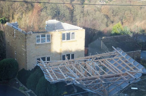
There are plenty of photos of damage wrought by past hurricanes to prove that the connection between the roof and the structure is a critical detail. In a previous blog post, I wrote about whose responsibility it is to specify a truss-to-wall connection (hint: it’s not the truss Designer’s). This blog post is going to focus on the proper specification of a truss-to-wall connection, the methods for evaluating those connections under combined loading and a little background on those methods (i.e., the fun stuff for engineers).
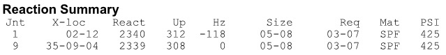
Take a quick look at a truss design drawing, and you will see a reaction summary that specifies the downward reaction, uplift and a horizontal reaction (if applicable) at each bearing location. Some people are tempted to look only at the uplift reaction, go to a catalog or web app, and find the lowest-cost hurricane tie with a capacity that meets or barely exceeds the uplift reaction.
However, if uplift was the only loading that needed to be resisted by a hurricane tie, why would we publish all those F1 and F2 allowable loads in our catalog?
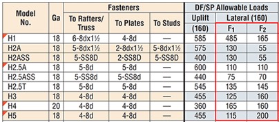
Of course, many of you know that those F1 and F2 allowable loads are used to resist the lateral loads acting on the end and side walls of the building, which are in addition to the uplift forces. Therefore, it is not adequate to select a hurricane tie based on uplift reactions alone.
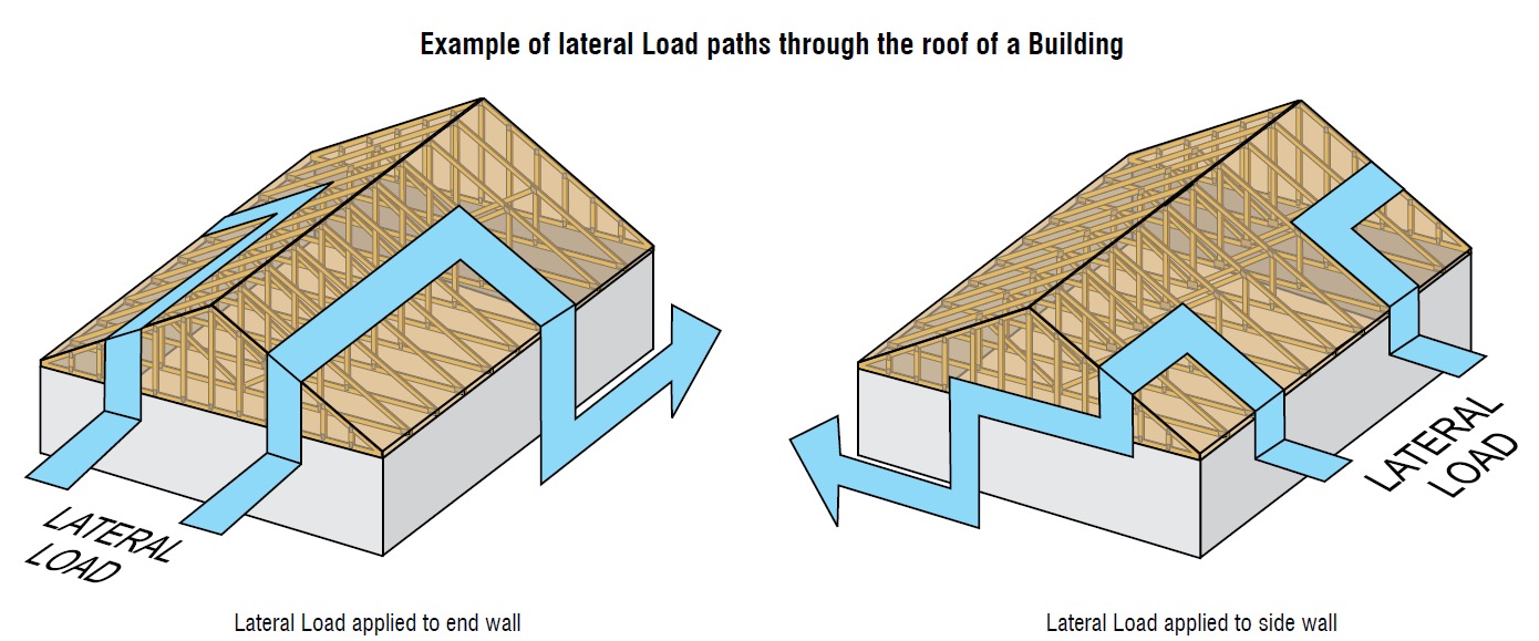
Where does one get the lateral loads parallel and perpendicular to the plate which must be resisted by the truss-to-wall connection? Definitely not from the truss design drawing! Unless otherwise noted, the horizontal reaction on a truss design should not be confused with a lateral reaction due to the wind acting on the walls – it is simply a horizontal reaction due to the wind load (or a drag load) being applied to the truss profile. It is also important to note that any truss-to-wall connection specified on a truss design drawing was most likely selected based on the uplift reaction alone. There may even be a note that says the connection is for “uplift only” and does not consider lateral loads. In this case, unless additional consideration is made for the lateral loads, the use of that connector alone would be inadequate.
Say, for example, that the uplift and lateral/shear load requirements for a truss-to-wall connection are as follows:
Uplift = 795 lb.
Shear (parallel-to-wall) = 185 lb. (F1)
Lateral (perp-to-wall) = 135 lb. (F2)
Based on those demand loads, will an H10A work?
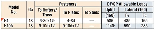
An initial look at the H10A’s allowable loads suggests it might be adequate. However, when these loads are entered into the Connector-Selector, no H10A solution is found.
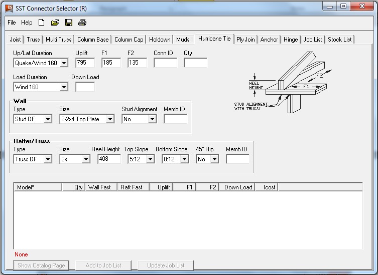
Why? Because Connector-Selector is evaluating the connector for simultaneous loading in more than one direction using a traditional linear interaction equation approach as specified in our catalog:
If the shear and lateral forces were to be resisted by another means, such that the H10A only had to resist the 795 lb. of uplift, then it would be an adequate connector for the job. For example, the F1 load might be resisted with blocking and RBC clips, and the F2 loads might be resisted with toe-nails that are used to attach the truss to the wall prior to the installation of the H10A connectors. However, if all three loads need to be resisted by the same connector, then the H10A is not adequate according to the linear interaction equation.

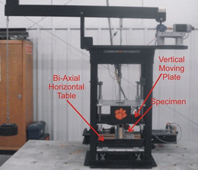
Some might question how valid this method of evaluation is – Is it necessary? Is it adequate? How do we know? And that is where the interesting information comes in. Several years ago, Simpson Strong-Tie partnered with Clemson University on an experimental study with the following primary objectives:
1. To verify the perceived notion that the capacity of the connector is reduced when loaded in more than one direction and that the linear interaction equation is conservative in acknowledging this combined load effect.
2. To propose an alternative, more efficient method if possible.
Three types of metal connectors were selected for this study – the H2.5A, H10, and the META20 strap – based on their different characteristics and ability to represent general classes of connectors. The connectors were subjected to uni-axial, bi-axial and tri-axial loads and the normalized capacities of the connectors were plotted along with different interaction/design surfaces.
These interaction plots were used to visualize and parameterize the combined load effect on the capacity of the connectors. The three different interaction plots that were examined were the traditional linear relationship, a quadratic interaction surface and a cuboid design space.
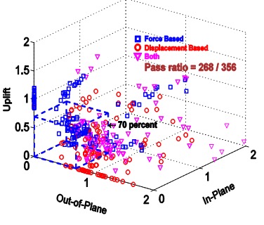
The results? Not only was the use of the linear interaction equation justified by this study, but a new, more efficient cuboid design surface was also identified. It provides twice the usable design space of the surface currently used for tri-axial loading and still provides for a safe design (and for the bi-axial case, it is even more conservative than the linear equation). This alternative method is given in our catalog as follows:

Now we can go back to the H10A and re-evaluate it using this alternative method:

As it turns out, the H10A does have adequate capacity to resist the simultaneous uplift, shear and lateral loads in this example. This just goes to show that the alternative method is definitely worth utilizing, whenever possible, especially when a connector fails the linear equation.
For more information about the study, see Evaluation of Three Typical Roof Framing-to-Top Plate/Concrete Simpson Strong-Tie Metal Connectors under Combined Loading.
What is your preferred method for resisting the combined shear, lateral and uplift forces acting on the truss-to-wall connections? Let us know in the comments below!