

Those of you who have been following the Simpson Strong-Tie SE Blog for a while may recall our 2013 blog post on the withdrawal resistance of stainless-steel nails. There have been several developments relating to that subject since that blog was posted, and we want to help you catch up.Continue Reading
Tag: NDS
Revisiting Spanning the Gap

Three years ago, we created this blog post based on a technical support question we often receive about allowable fastener loads for ledgers to wood framing over gypsum board. Given that this is still a frequent question and a relevant topic, we decided to revisit the post and update it.
Drywall. Wall board. Sheetrock. Sackett Board? A product called Sackett Board was invented in the 1890s, which was made by plastering within wool felt paper. United States Gypsum Corporation refined Sackett Board for several years until 1916, when they developed a new method of producing boards with a single layer of plaster and paper. This innovation was eventually branded SHEETROCK®. More details about the history of USG can be found here.
No matter what you call it, gypsum board is found in almost every type of construction. Architects use it for sound and fire ratings, while structural engineers need to account for its weight in our load calculations. A common technical support question we receive is for allowable fastener loads for ledgers to wood framing over gypsum board.
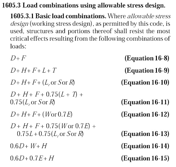
One method to evaluate a fastener spanning across gypsum board is to treat the gypsum material as an air gap. Technical Report 12, General Dowel Equations for Calculating Lateral Connection Values, is published by the American Wood Council.

TR12 has yield limit equations that allow a designer to account for a gap between the main member and side member of a connection. With a gap of zero (g=0), the TR12 equations provide the same results as the NDS yield limit equations.
![Technical Report 12 Yield Limit Equations[1]](http://seblog.strongtie.com/wp-content/uploads/2014/01/Technical-Report-12-Yield-Limit-Equations1.jpg)
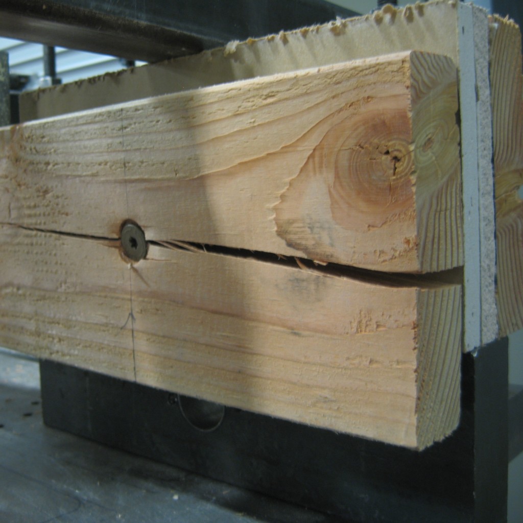
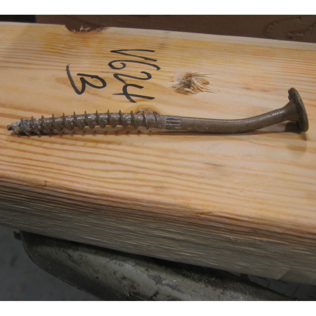
Testing, of course! In So, What’s Behind a Screw’s Allowable Load? I discussed the methods used to load rate a proprietary fastener such as the Simpson Strong-Tie® Strong-Drive® SDS or SDW screws. To recap, ICC-ES Acceptance Criteria for Alternate Dowel Type Fasteners, AC233, allows you to calculate and do verification tests, or load rate based on testing alone. We develop our allowable loads primarily by testing, as the performance enhancing features and material optimizations in our fasteners are not addressed by NDS equations.
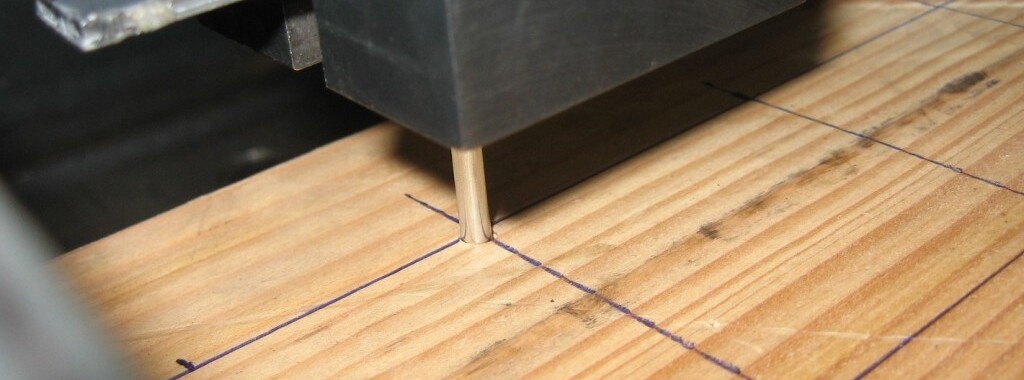
So to determine the performance of a fastener installed through gypsum board, we tested the fastener through gypsum board. This is easier to do if you happen to have a test lab with a lot of wood and fasteners in it. We did have to run down to the local hardware store to pick up gypsum board for the testing.
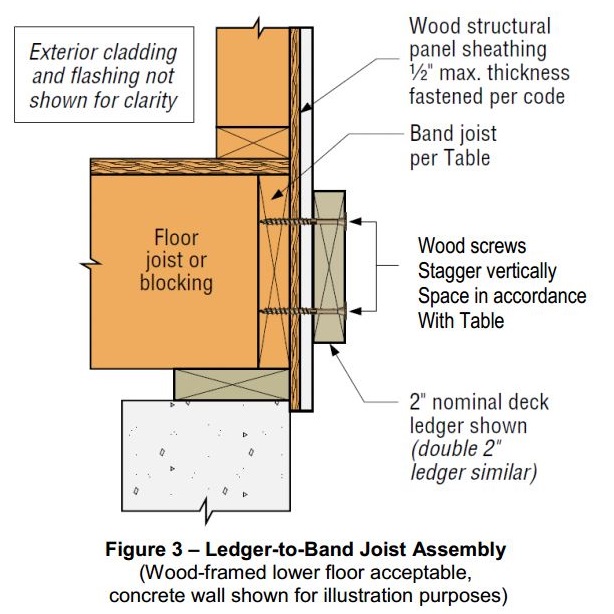
A full set of allowable loads for Strong-Drive SDWH and SDWS are available on strongtie.com. The information is given as single fastener shear values for engineered design, and also screw spacing tables for common ledger configurations. As much fun as writing spreadsheets to do the Technical Report 12 calculations is, having tabulated values based on testing is much easier.
Fastening Systems
In the fastener marketplace, Simpson Strong-Tie stands apart from the rest. Quality and reliability is our top priority.

Narrow Face Installations
Engineered wood products have been used in wood-framed construction for many decades. Early forms of engineered wood include plywood as replacement for 1x wood sheathing and glu-laminated beams that could be fabricated in larger sizes with optimized material utilization. I-joists utilizing deep plywood webs and solid sawn lumber flanges solved the challenge of longer floor spans. Oriented strand board (OSB) eventually replaced plywood in the webs, while the innovation of laminated veneer lumber (LVL) became common in the flange material.
In addition to I-joists, structural composite lumber is widely used as a replacement for solid lumber. This could be for a number of reasons such as availability of longer lengths, straighter sections and higher strengths. Structural composite lumber (SCL) may be LVL, parallel strand lumber (PSL), laminated strand lumber (LSL) or oriented strand board (OSB).
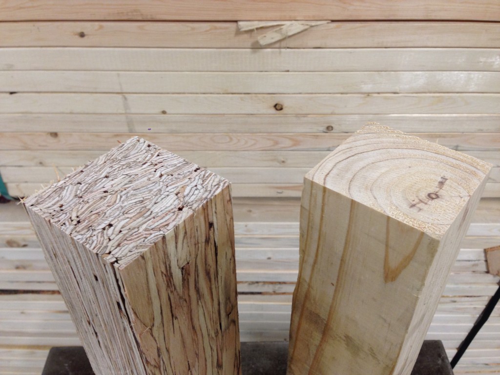
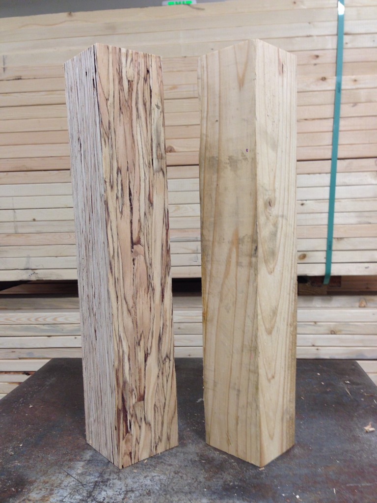
Structural composite lumber has two faces. If the cross-section is rectangular, say 3½x5¼, the narrow face will show the edges of the SCL layers. In a square section, the face that shows the SCL layers is still referred to as the narrow face. Fasteners will have lower performance when they are installed in the narrow face of SCL. While this is not an issue for beams, Simpson Strong-Tie connectors such as post bases, column caps or holdowns may have reduced allowable loads when installed on the narrow face of SCL columns.
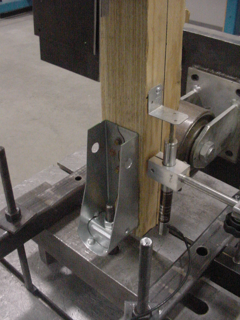
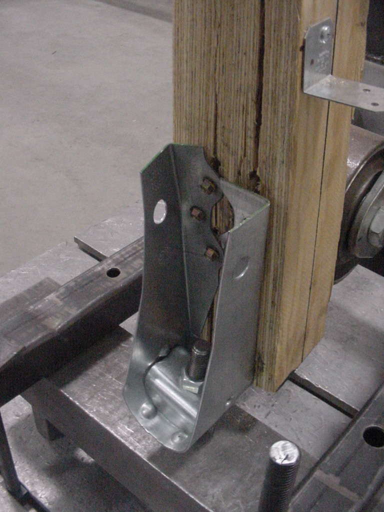

To support the use of Simpson Strong-Tie connectors installed on SCL post material, we have run many tests over the years. The reductions are published in the technical bulletins, T-SCLCLM13 (U.S. version) and T-C-SCLCLMCAN13 (Canada version). The reduction factors range from 0.45 to 1.0, and vary based on SCL material type – LSL, PSL, or LVL – and also by connector and fastener type.
It is important to understand the magnitude of the reductions. While narrow face installations may be unavoidable, engineers will need to specify the correct lumber and hardware combination to meet the design loads.
Share additional thoughts by leaving a comment.
Are the Load Combinations Balanced?
In April’s post about the Omega Factor, one commenter asked of the 1.2 increase allowed by ASCE 12.4.3.3, “Why do they allow a stress increase for allowable combinations? Seems unconservative for steel now that they have essentially balanced the ASD capacity with LRFD.”
To be honest, I have never spent much time analyzing which design methodology was more or less conservative. If I was designing with wood I would use ASD, and if it was with concrete I would use LRFD. Steel was strictly ASD early on in my design career, but LRFD usage grew. The question about balance made me curious. Are the load combinations balanced?
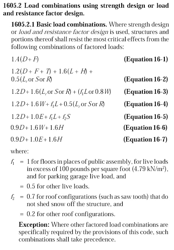
Of course, just comparing the load combinations would be meaningless. We know the LRFD combinations result in higher design forces. But those higher forces are compared to higher design strengths. So we need to normalize things.

Why Won’t The Wood Fit? Understanding Lumber Size
Lumber size is often given in “nominal” measurements. This can often lead to confusion when someone is shopping for wood and wood connectors. Paul McEntee, Simpson Strong-Tie Manager of Engineering R&D, addressed lumber sizes and how our company takes them into consideration during product development and testing.
Why Won't The Wood Fit?
Your wood fastening products seem to be built for yesteryear wood sizes. 2x’s are no longer larger than 1½”. Why can’t you manufacture these products with a little closer tolerance?
I received this question from a customer a few days ago via Ask Simpson, a web page where you can submit technical questions to our Engineering Department and we respond by e-mail. We have received similar variations of this question countless times over the years, so I thought it could use some discussion.
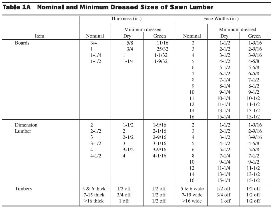
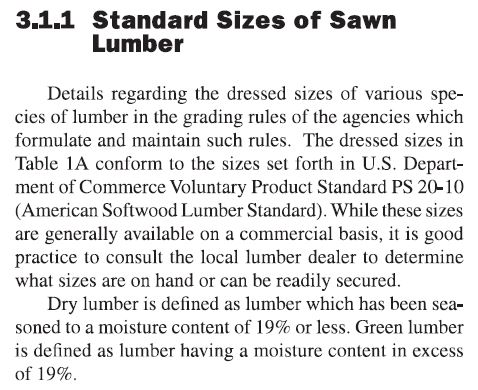
The National Design Specification for Wood Construction (NDS) Supplement Table 1A “Nominal and Minimum Dressed Sizes of Sawn Lumber” gives the minimum dry and green dimensions for sawn lumber. This specifies a nominal 2x, for example, as being 1½” dry and 1 9/16” green. NDS Supplement Section 3.1.1 defines dry lumber being seasoned to a moisture content of 19% or less, whereas green lumber is higher than 19%.
So what size do you make the connector?
Continue Reading