

Whether you’re designing and building a one- or two-story single-family residence, or doing the same for a multifamily, mid-rise wood-frame structure, fire and smoke protection features must be considered, and in most cases are required. When a fire starts, time is of the essence and the longer the flame and gases can be contained and the spread of the fire to adjacent spaces is kept in check, the greater the chance firefighters and first responders will have to defeat the blaze. Though many building jurisdictions have slightly different requirements and provisions, the three primary modes of fire rating that codes consider are an F-rating (flame), a T-rating (temperature rise), and an L-rating (air or gas leakage). The F and T ratings are gauged on a resistance per hour basis and the L rating is based on a rating of air leakage in cubic feet per minute per square foot of opening, or CFM/sq.ft. These ratings and provisions are in place to help safeguard against the spread of fire and smoke within the immediate structure as well as to contain the spread of fire to other structures.
Tag: Strong-Rod Systems
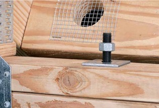
Shrinkage Compensation Devices
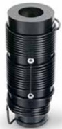
Over the weekend, I had the pleasure of watching my daughter in her cheer competition. I was amazed at all the intricate detail they had to remember and practice. The entire team had to move in sync to create a routine filed with jumps, tumbles, flyers and kicks. This attention to detail reminded me of the new ratcheting take-up device (RTUD) that Simpson Strong-Tie has just developed to accommodate 5/8″ and ¾” diameter rods. The synchronized movement of the internal inserts allows the rod to move smoothly through the device as it ratchets. The new RTUDs are cost effective and allow unlimited movement to mitigate wood shrinkage in a multi-story wood- framed building. When designing such a building, the Designer needs to consider the effect of shrinkage and how to properly mitigate it.
Our SE blog post on Continuous Rod Restraint Systems for Multi-Story Wood Structures explained the importance of load path and the effects of wood shrinkage. This week’s blog post will focus on the importance of mitigating the shrinkage that typically occurs in multi-story light-frame buildings.
Shrinkage is natural in a wood member. As moisture reaches its equilibrium in a built environment, the volume of a wood member decreases. The decrease in moisture causes a wood-framed building to shrink.
The IBC allows construction of light-framed buildings up to 5 and 6 stories in the United States and Canada respectively. Based on the type of floor framing system, the incremental shrinkage can be up to ¼” or more per floor. In a 5-story building, that can add up to 1-¼” or more and possibly double that when construction settlement is included.
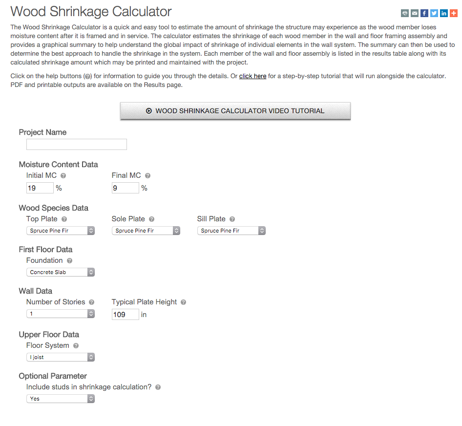
The Simpson Strong-Tie Wood Shrinkage Calculator is a perfect tool to determine the total shrinkage your building can experience.
In order to accommodate the shrinkage that occurs in a multi-story wood-framed building, Simpson Strong-Tie offers several shrinkage compensating devices. These devices have been tested per ICC-ES Acceptance Criteria 316 (AC316) and are listed under ICC-ES ESR-2320 (currently being updated for the new RTUD5, RTUD6, and ATUD9-3).
AC316 limits the rod elongation and device displacement to 0.2 inches between restraints in shearwalls. This deflection limit is to be used in calculating the total lateral drift of a light-framed wood shearwall.
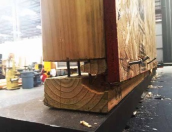
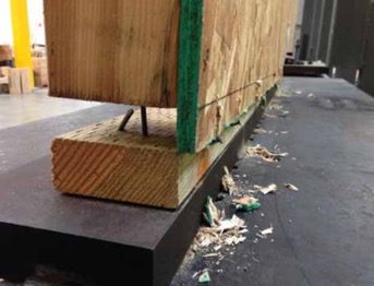
The 0.2-inch allowable limit prescribed in AC316 is important to a shearwall’s structural ability to transfer the necessary lateral loads through the structure below to the foundation level. This limit assures that the structural integrity of the nails and sill plates used to transfer the lateral loads through the shearwalls is not compromised during a seismic or wind event. Testing has shown that sill plates can crack when excessive deformation is observed in a shearwalls. Nails have also been observed to pull out during testing. Additional information on this can be found here.
In AC316, 3 types of devices are listed.
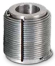
- Compression-Controlled Shrinkage Compensating Device (CCSCD): This type of device is controlled by compression loading, where the rod passes uninterrupted through the device. Simpson Strong-Tie has several screw-type take-up devices, such as the Aluminum Take-Up Device (ATUD) and the Steel Take-Up Device (TUD), of this type.
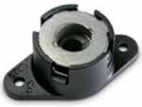
Tension-Controlled Shrinkage Compensating Device (TCSCD): This type of device is controlled by tension loading, where the rod is attached or engaged by the device and allows the rod to ratchet through as the wood shrinks. The Simpson Strong-Tie Ratcheting Take-Up Device (RTUD) is of this type.
- Tension-controlled Shrinkage Compensating Coupling Device (TCSCCD): This type of device is controlled by tension loading that connects rods or anchors together. The Simpson Strong-Tie Coupling Take-Up Device (CTUD) is of this type.
Each device type has unique features that are important in achieving the best performance for different conditions and loads. The following table is a summary of each device.
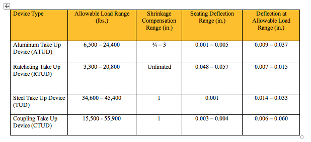 The most cost-effective Simpson Strong-Tie shrinkage compensation device is the RTUD. This device has the smallest number of components and allows the rod unlimited travel through the device. It is ideal at the top level of a rod system run or where small rod diameters are used. Simpson Strong-Tie RTUDs can now accommodate 5/8″ (RTUD5) and ¾” (RTUD6) diameter rods.
How do you choose the best device for your projects? A Designer will have to consider the following during their design.
Rod Tension (Overturning) Check:
- Rods at each level designed to meet the cumulative overturning tension force per level
- Standard and high-strength steel rods designed not to exceed tensile capacity as defined in AISC specification
- Standard threaded rod based on 36 / 58 ksi (Fy/Fu)
- High-strength Strong-Rod based on 92 / 120 ksi (Fy/Fu
- H150 Strong-Rod based on 130 / 150 ksi (Fy/Fu)
- Rod elongation (see below)
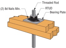
Bearing Plate Check
- Bearing plates designed to transfer incremental overturning force per level into the rod
- Bearing stress on wood member limited in accordance with the NDS to provide proper bearing capacity and limit wood crushing
- Bearing plate thickness has been sized to limit plate bending in order to provide full bearing on wood member
Shrinkage Take-Up Device Check
- Shrinkage take-up device is selected to accommodate estimated wood shrinkage to eliminate gaps in the system load path
- Load capacity of the take-up device compared with incremental overturning force to ensure that load is transferred into rod
- Shrinkage compensation device deflection is included in system displacement
Movement/Deflection Check
- System deformation is an integral design component impacting the selection of rods, bearing plates and shrinkage take-up devices
- Rod elongation plus take-up device displacement is limited to a maximum of 0.2″ per level or as further limited by the requirements of the engineer or jurisdiction
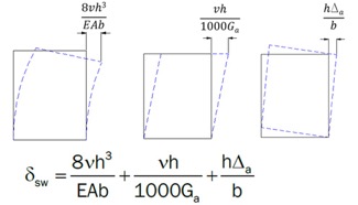
- Total system deformation reported for use in Δa term (total vertical elongation of wall anchorage system per NDS equation) when calculating shearwall deflection
- Both seating increment (ΔR) and deflection at allowable load (ΔA) are included in the overall system movement. These are listed in the evaluation report ICC-ES ESR-2320 for take-up devices
Optional Compression Post Design
- Compression post design can be performed upon request along with the Strong-Rod System
- Compression post design limited to buckling or bearing perpendicular to grain on wood plate
- Anchorage design tools are available
- Anchorage design information conforms to AC 318 anchorage provisions and Simpson Strong-Tie testing
In order to properly design a continuous rod tie-down system for your shearwall overturning restraint, all of the factors listed above will need to be taken into consideration.
A Designer can also contact Simpson Strong-Tie by going to www.strongtie.com/srs and filling out the online “Contact Us” page to have Simpson Strong-Tie design the continuous rod tie-down system for you. This design service does not cost you a dime. A few items will be required from the Designer in order for Simpson Strong-Tie to create a cost-effective rod run (it is recommended that on the Designer specify these in the construction documents):
- There is a maximum system displacement of 0.2″ per level, which includes rod elongation and shrinkage compensation device deflection. Some jurisdictions may impose a smaller deflection limit.
- Bearing plates and shrinkage compensation devices are required at every level.
- Cumulative and incremental forces must be listed at each level in Allowable Stress Design (ASD) force levels.
- Construction documents must include drawings and calculations proving that design requirements have been met. These drawings and calculations should be submitted to the Designer for review and the Authority Having Jurisdiction for approval.
More information can be obtained from our website at www.strongtie.com/srs, where a new design guide for the U.S., F-L-SRS15, and a new catalog for Canada, C-L-SRSCAN16, are available for download.
Continuous Rod Restraint Systems for Multi-Story Wood Structures
This week was our new employee Sales and Product Orientation class. It reminded me of the post A Little Fun with Testing where we broke a bowling ball. Although breaking stuff is fun, my second favorite part of the class is teaching about the importance of a continuous load path. I think it is really the most important thing a Structural Engineer does. If we don’t pay attention to the loads, where they occur and create a path so they can get where they need to go, a building may not stand up. This week, we also released some new tools and information for our new Strong-Rod™ Systems, which are used to complete the load path for multi-story wood-framed shearwall overturning restraint and roof uplift restraint.
Two Load Paths
All wood-framed buildings need to be designed to resist shearwall overturning and roof-uplift forces. To transfer these tensile forces through the load path, connectors (hurricane ties, straps and holdowns) have been the traditional answer. Simpson Strong-Tie offers a few options there. With the growth in multi-story wood-framed structures, where the code requires shrinkage to be addressed and overturning and uplift forces are typically higher, rod systems have become an increasingly popular load restraint solution. Our Anchor Tiedown System (ATS) for shearwall overturning restraint has been around for many years. A new Strong-Rod Systems Design Guide and revamped web pages provide information on new design options, components and configurations.
The guide and website focus more on the unique design considerations for rod systems, how you should specify the system and highlight the design services that we provide. They also provide more detail and design information for our relatively new Uplift Restraint System (URS) for roofs. Connectors are a common choice for transferring the net roof uplift forces from wind events down the structure. Although in some high-wind areas, rod systems are preferred.
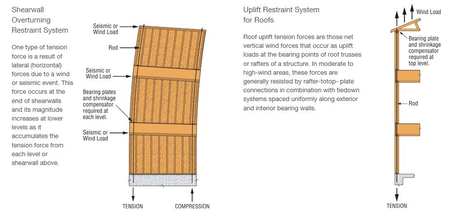
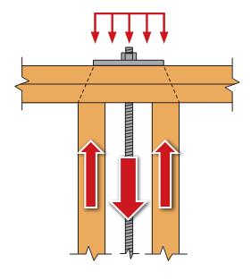
I’ll touch on some of the design considerations for these types of systems below, but back to the load path. For shearwall overturning restraint using holdowns, the load path is fairly simple. Once the lateral load is in the shearwall, the sheathing and nailing lifts up on the post. The holdown connects to the post, holding it down and transferring the forces to the foundation or level below. A continuous rod tiedown system follows a little different path. The sheathing and nailing lifts up on the boundary posts and the posts push up on the framing above until the load is resisted in bearing by a bearing plate. The load is then transferred into the rod and down to the foundation. There has been a lot of testing and research on the effects of skipping restraint locations where a bearing plate restraint is installed at every other floor or only at the top level. Doing that will change the load path because the load has to continue to travel up until a restraint holds it down. It also negatively impacts the stiffness and drift of the shearwall stack, not to mention increases project cost because the boundary posts, rod and bearing must be sized to transfer the cumulative overturning forces from each level.
Wood Shrinkage, Take-up Devices and Displacement Limits
Shrinkage is not just a Seinfeld episode cult classic. It is also something that designers need to consider when designing wood structures. IBC Section 2304.3.3 requires that designers evaluate the impact of wood shrinkage on the building structure when bearing walls support more than two floors and a roof. The effects of wood shrinkage can impact many things in the structure from finishes to MEP systems to the continuous rod system. As the wood members lose moisture, the wood shrinks and the building settles. This can cause gaps at the bearing plate locations of continuous rod systems because the continuous steel rod doesn’t shrink. That is where the magic of take-up devices comes in. They allow the building to shrink but keep gaps from forming by filling the gap (expanding devices – can be screw style or ratcheting), ratcheting down the rod (ratcheting devices), or making the rod shrink as much as the wood (contracting coupling device).
In addition to keeping the rod system tight to insure the intended performance, it is important to consider the movement associated with the rod system when under wind or earthquake loading. The IBC requires shearwall displacements to be within story drift limits in moderate to high seismic regions. We highlighted some of the changes coming for the evaluation of shearwall deflection in the previous post discussing the New Treatment of Shear Wall Aspect Ratios in the 2015 SDPWS. For continuous rod systems, there are some additional limits. ICC-ES AC316 Acceptance Criteria for Shrinkage Compensating Devices requires designs to limit displacement between restraints to 0.20 inches (including rod elongation and device displacement) for shearwall restraint. The movement of the take-up device plays a big part in meeting this requirement and the rod diameter required. Screw-style devices have the lowest total movement. Ratcheting devices are appropriate in many cases as well such as the upper levels where loads are lower, but may require larger rod diameters to meet the displacement limit.
 ICC-ES AC391 Acceptance Criteria for Continuous Rod Tie-down Runs and Continuous Rod Tie-down Systems Used to Resist Wind Uplift covers continuous rod systems for roof uplift restraint. The displacement limit for the Continuous Rod Tie-down Run (just the rod system components) is limited to 0.18 inches of rod elongation for the total length of rod. The Strong-Rod URS evaluates the Continuous Rod Tie-down System (the whole load path). Displacement limits for the system are L/240 for the top plate bending and 0.25 inches total deflection at the top plate between tie-down runs (including top plate bending, rod elongation, wood bearing deformation and take-up device displacement). The differences between the rod run and rod system analysis as well as other design considerations are explained in more detail in the design guide and on our website.
I always end my continuous load path presentation during orientation class with the same questions and if they were paying attention I get the response I want.
“What is the most important thing a Structural Engineer does?”
“Designs a continuous load path for the building!”
“What does Simpson Strong-Tie do?”
“Provides product and system solutions to help engineers do their job!”
Take a look at the new Strong-Rod Systems tools and information and let us know how we can help you with your next multi-story wood-framed project.
What related blog topics would you like to discuss? Let us know in the comments below.