

One interesting part of being a field engineer for Simpson Strong-Tie is having the opportunity to see how different structural engineers may take different approaches to similar designs. We at Simpson Strong-Tie have come to appreciate these different approaches and embrace this phenomenon by providing multiple resources to aid in the completion of a design. This is very apparent when it comes to the design of post-installed anchors.
Tag: titen hd
Providing Performance Data for Shallowly Embedded Anchors
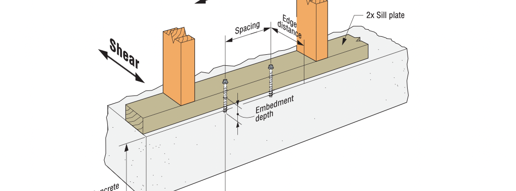
In the last few years, Simpson Strong-Tie has heard from a number of structural engineers expressing frustration with the lack of performance data for shallowly embedded, post-installed anchors (shallow anchors). Engineers of Record (EOR) have identified a common application for shallow anchors as those related to attachment of sill plates for structural and nonstructural wall-to-podium slab connections. One dilemma faced by the EORs originates in their desire to prevent damage to concrete podium slab reinforcement, especially where reinforcement is located close to the slab’s top surface to resist negative bending moments. EORs further indicate that shallow anchors are frequently needed for the following attachments: hanging MEP fixtures; attaching nonstructural components associated with tenant improvements; and anchoring light equipment.
Why You Should Specify Stainless-Steel Screw Anchors When Designing for Corrosive Environments
I was driving under a concrete bridge one nice clear day in Chicago, and I happened to look up to see rusted rebar exposed below a concrete bridge. My beautiful wife, who is not a structural engineer, turned to me and asked, “What happened to that bridge?” I explained that there are many reasons why spalling occurs below a bridge. One common reason is the expansion of steel when it rusts or corrodes.
Concrete Anchor Design for the International Building Code: Part 1
Purpose
The intent of this technical bulletin is to clarify code language and outline the correct path for the design of concrete anchors under the International Building Code (IBC). The reader will be able to clearly distinguish between “code anchors” and anchors that are considered “alternative materials,” as well as understand the logical sequence of code language for designing each type. The distinction between “cracked” concrete and “uncracked” concrete anchor design will be made. This technical bulletin will lend clarity to the qualification of post-installed anchors for use in concrete. Excerpts from the IBC and its Referenced Standards will be provided to facilitate the description of the design requirements.
Background
More than a decade after the introduction of the American Concrete Institute’s ACI 318, Appendix D design methodology for anchor design in 2002, many design professionals either do not fully understand or are unaware of the code requirements for the design of concrete anchors. Several factors contribute to the challenges associated with understanding the code mandates:
1. The incorrect notion that ACI 318, Appendix D is exclusively for anchors designed for “cracked concrete,” leading to regionally varying degrees of enforcement and implementation of the design requirements
2. Multiple Reference Standards for the design and qualification of different anchor types
3. The evolving scope of Reference Standards, which have reclassified some anchors as “Code Anchors” that were previously considered “Alternative Materials”
4. Confusing language in IBC sections that address concrete anchorage
5. Complexity of the anchor design methodology itself
6. Varying levels of special inspections enforcement
It is nevertheless incumbent upon the licensed design professional to design anchors in accordance with the minimum provisions of the code in order to protect public safety, reduce liability risk and fulfill professional responsibilities.
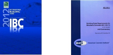
The International Building Code, beginning with the 2000 edition, describes the design methodology of concrete anchors by virtue of the language within the IBC itself, or through language in the Referenced Standard (ACI 318). In this technical bulletin, specific reference to the 2012 IBC and ACI 318-11 will be made, since this is currently the most widely adopted edition of the IBC.
“Code Anchors” and “Alternative Materials”
Anchors can be divided into two major categories: 1) “Code Anchors”, which are those that are specifically addressed in the IBC or its Referenced Standards, and 2) “Alternative Materials”, the design and qualification of which are not addressed in the IBC or its Referenced Standards.
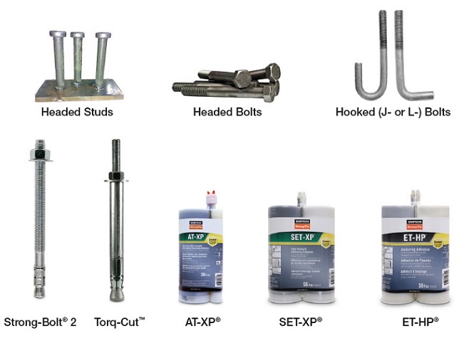
The following “Code Anchors” recognized by the 2012 IBC:
- Headed studs
- Headed bolts
- Hooked (J- or L-) bolts
- Expansion anchors(such as Simpson Strong-Tie® Strong-Bolt® 2)
- Undercut anchors (such as Simpson Strong-Tie® Torq-Cut™)
- Adhesive anchors (such as Simpson Strong-Tie® SET-XP®, AT-XP®, and ET-HP®)
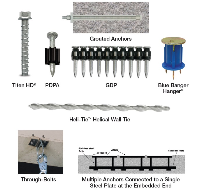
Anchor types not listed above are considered “Alternative Materials.”
The following are anchors qualified as such:
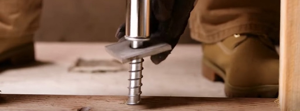
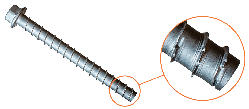
- Screw anchors (such as Simpson Strong-Tie® Titen HD®)
Alternative materials also apply to anchor types specifically excluded from ACI 318-11 calculation and analysis requirements.
- Specialty inserts (such as Simpson Strong-Tie® Blue Banger Hanger®)
- Through-bolts
- Multiple anchors connected to a single steel plate at the embedded end
- Grouted anchors
- Powder- or gas-actuated fasteners (such as Simpson Strong-Tie® PDPA)
Designing “Code Anchors”
The starting point for the design of all anchors is Section 1908 of the 2012 IBC.
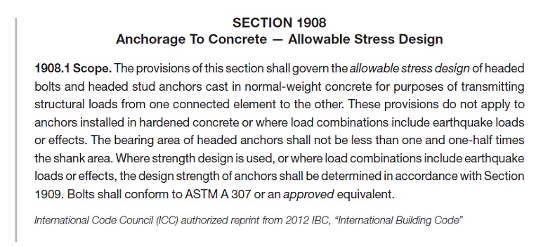
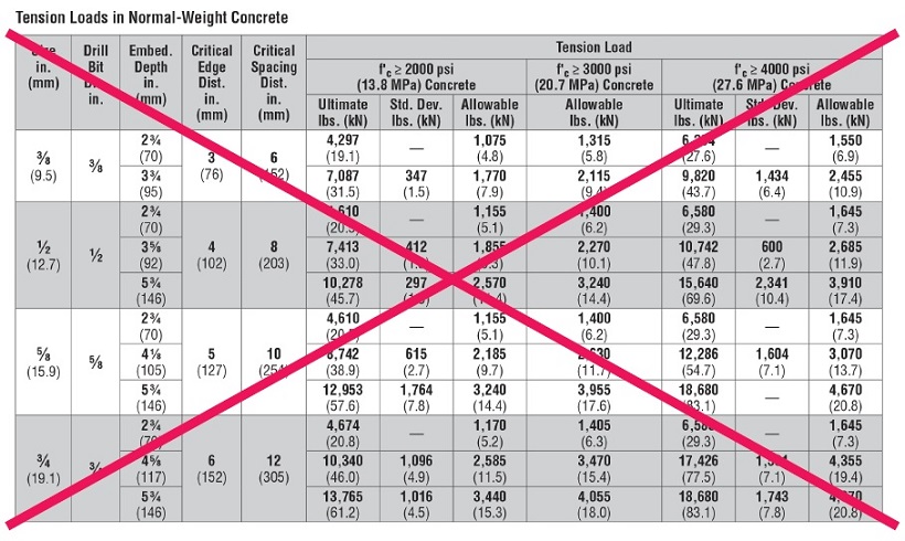
Section 1908.1 states that only cast-in-place headed bolts and headed studs are permitted to be designed using “Allowable Stress Design,” provided that they are not used to resist earthquake loads or effects. For these anchors, Section 1908.2 references Table 1908.2 for the determination of the allowable service load. Section 1908.1 makes explicit reference to post-installed anchors (anchors installed into hardened concrete), stating that the provisions of “Allowable Stress Design” is not permitted. For the design professional, this means that determining anchor by means of “Allowable Load Tables” based on previous test criteria that used a safety factor of 4.0 to determine allowable loads, as in the example below, is not permitted under the IBC.
Section 1909 of the 2012 IBC, “Anchorage to Concrete – Strength Design” makes explicit reference to Appendix D of ACI 318 as the required design standard for the anchors listed in this section.
Cast-in-place headed bolts and headed studs used to resist earthquake loads or effects must be designed using “Strength Design” in accordance with ACI 318 Appendix D. Additionally, Section 1909 does not make reference to adhesive anchors, despite their status as “code anchors.” ACI 318-11 was the first edition to include adhesive anchors in its scope; however, the 2012 IBC was approved prior to the approval of ACI 318-11. This resulted in the omission of adhesive anchors from the language in Section 1909 of the 2012 IBC. Section 1901.3 of the 2015 IBC, entitled “Anchoring to Concrete” includes language for adhesive anchors and their applicability to the ACI 318-14 design and qualification requirements. The omission of adhesive anchors from Section 1909 of the 2012 IBC, however, does not exclude them from the design and qualification requirements of ACI 318-11 by virtue of their inclusion in ACI 318-11 Section D.2.2. The design professional must then reference Section D.2 of ACI 318-11, Appendix D to confirm that the anchors being designed fall within its scope.
Note that anchors used for temporary construction means, such as tilt wall panel bracing, are not addressed in the IBC. As a result, they are not required to be designed in accordance with the provisions of ACI 318, Appendix D. Section D.2.2 lists anchor types that fall within its scope, and those that are excluded (considered “Alternative Materials”).
Code Anchors are required to meet the ACI 318-11 Section D.2.3 qualification requirements described below.
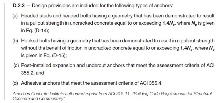
ACI 355.2 (Qualification standard for expansion and undercut anchors) and ACI 355.4 (Qualification standard for adhesive anchors) are referenced here as the qualification criteria for specific types of postinstalled anchors. For the design professional it can be difficult to determine, without fully investigating these Referenced Standards, whether a specific proprietary anchor has been tested and is qualified for use in concrete. A simpler means by which to identify whether a proprietary anchor has been qualified to the Referenced Standard is a current Research Report (e.g., Evaluation or Code Report) which provides third-party review and verification that the product has been tested to and meets the qualification standard. There are two primary Research Report providers: IAPMO UES (International Association of Plumbing & Mechanical Officials Uniform Evaluation Service) and ICC-ES (International Code Council Evaluation Service).
These agencies are ANSI ISO 17065 accredited. They review independent laboratory test data, witnessed or conducted by an accredited third party, for a product and verify its conformance to publicly developed and majority-approved qualification criteria (or acceptance criteria) established for a given anchor type. Research Reports are an invaluable tool to the design professional and building official as evidence of conformance with the IBC.
There are two acceptance criteria that apply to post-installed “Code Anchors”:
- ICC-ES AC193 – Acceptance Criteria for Post-Installed Mechanical Anchors in Concrete Elements
- ICC-ES AC308 – Acceptance Criteria for Post-Installed Adhesive Anchors in Concrete Elements
These acceptance criteria reference ACI 355.2 and ACI 355.4, respectively, as the foundation for the test program by which the anchor is evaluated, and establish minimum performance standards for qualification. A Research Report is issued for an anchor that meets these minimum standards.
Newest Connector to Satisfy Code
“Does Simpson Strong-Tie write the building code?”
If you work at Simpson Strong-Tie, you get asked this question from time to time when you’re in the field. Over the years, I’ve heard it dozens of times, and because the answer is obviously “no,” it makes you wonder why this belief persists with so many people in the industry. Well, here is my theory: We develop and test products for new code provisions faster than it takes states to adopt the newest codes. So a designer, contractor or building official will often hear about a new Simpson Strong-Tie product or tested application that fills a need before their state building code even defines what that need is. Here are some recent examples:
- The FWAZ foundation anchor released in 2007 for a 2006 IRC provision that addresses soil pressure loads on basement walls
- Strong-Drive® SDS screw testing for deck ledgers published in 2008 as alternates to bolts and lags that weren’t prescribed in the IRC until the 2009 edition
- The DTT2 deck tension tie released in 2009 is used for a 2009 IRC provision that addresses lateral loads on decks
- BPS ½ -6 bearing plate released in 2011 to address new provisions for shear wall bearing plates in the 2008 SDPWS, which is referenced in the 2009 and 2012 IBC
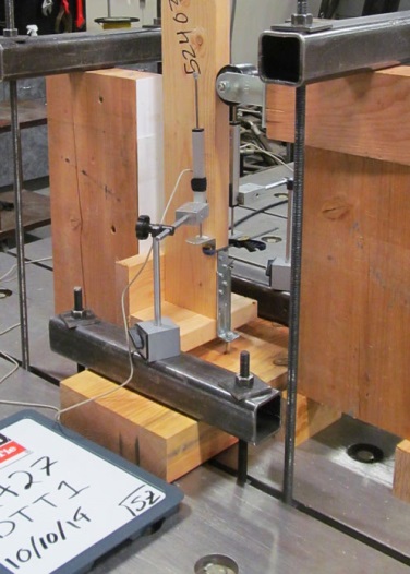
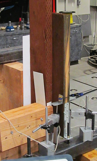
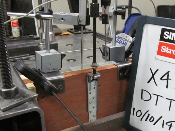
The latest example is the DTT1Z deck tension tie. Two of our engineers, Randy Shackelford and David Finkenbinder, attended the ICC hearings that resulted in the new 2015 IRC. As soon as a new provision was passed to provide an alternate 750-pound deck lateral load connection (submitted by Washington Assoc. of Building Officials, not Simpson Strong-Tie) we began working on a connector designed to do the job. After several months of R&D, field trials and new tooling, our presses began to stamp out the first production run of the DTT1Z to meet the 2015 IRC provision on December 30, 2014.

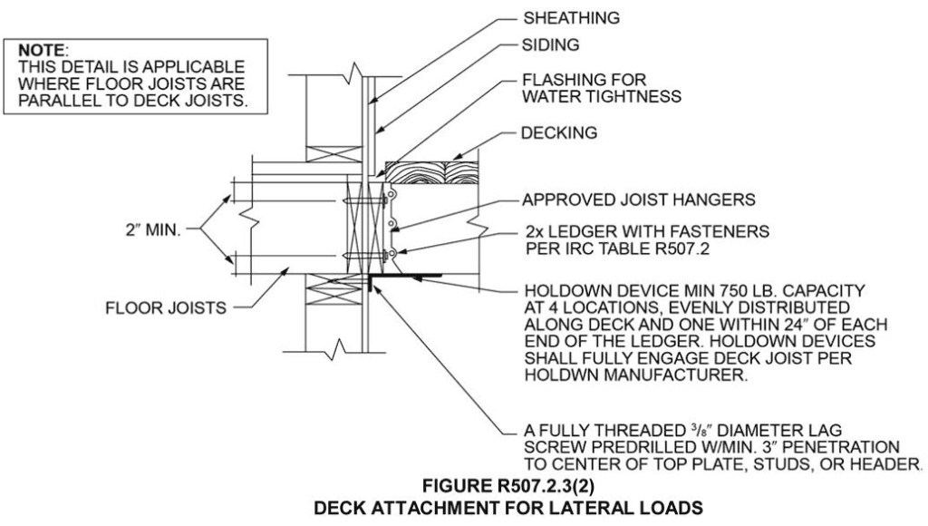
The IRC detail shows an ideal condition where the bottom of the deck joist lines up with the wall plates in the house. We tested this application, but we also wanted to support variations that may come up in the field. The results of this testing appear in our T-C-DECKLAT15 technical bulletin. We also tested the DTT1Z with our Strong-Drive® SDWH Timber-Hex HDG screw and our Titen HD® concrete screw anchor so it can be used in a variety of applications, including prescriptive wall bracing and (very) light shear walls. Many of these applications are covered in the code report (ER130) that was completed just this past week.
If you are interested in reading more about the new IRC deck provisions, Randy wrote about them in his Code Corner column in the current Structural Report and David wrote about them in this blog last August.
In case you are wondering how I respond when asked if we write the code, lately I have been answering it with another question: No, but do you know who is responsible for writing the code? My answer to this is “all of us.” If you don’t like what is in there now, work with an association that represents your interests (NCSEA for a lot of us) to submit a code-change proposal, or even submit one yourself. There is no guarantee it will get in, but if it involves a connection, I can guarantee we will get working on it right away!
Let us know if you see a need for a new connection product. If you already have a product idea and would like to work with us to develop it, you can more-formally submit it here.