The Greek philosopher Heraclitusis credited with saying “The only thing that is constant is change.”
If that applies to building codes, then it applies doubly to wind design using the 2012 International Building Code® (IBC).
The wind load requirements in Section 1609 of the IBC are based on ASCE 7 and refer to this document for most design information. In the 2012 IBC, the referenced version of ASCE 7 changed from the 2005 edition to the 2010 edition. In ASCE 7-10, the wind design requirements have been completely revised, including a complete design philosophy change.
Wind design has changed from an allowable strength-based philosophy with a load factor of 1 in the ASD load combination to an ultimate strength design philosophy with a load factor of 1 in the strength design load combination. This means wind design has a similar basis as seismic design. So the new load combinations for wind look like this:
Strength Design: 0.9D + 1.0W
Allowable Stress Design: 0.6D + 0.6W
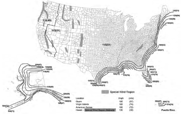
Because of the change in load factor and philosophy, the basic wind speed map had to be altered. In the past, one map was provided and the design return period was increased for certain occupancies by multiplying the load by an importance factor. In ASCE 7-10 there are three maps provided so now an importance factor is no longer needed. The return period of the map depends on the risk to human life, health and welfare that would result from the failure of that type of building. This was previously called the Occupancy Category, but it is now called the Risk Category.
Risk Category III and IV buildings use a basic wind speed map based on a 1,700-year return period. Risk Category II buildings use a basic wind speed map based on a 700-year return period. And Risk Category I buildings use a basic wind speed map based on a 300-year return period. Because of the higher return period, the mapped design wind speed will be much higher than when using previous maps. However, with the lower load factors, actual design loads will be the same or in many areas lower due to other changes in the way the map was developed.

Another change to ASCE 7-10 for wind design is that Exposure D is no longer excluded from hurricane prone regions; so buildings exposed to large bodies of water in hurricane prone regions will have to be designed for Exposure D.
Because of the change in wind speeds, there is a change in the definitions of windborne debris regions. Due to the different wind speed design maps, the windborne debris region will be different depending on the Risk Category of the building being built. The windborne debris region is now defined as areas within hurricane-prone regions that are either within 1 mile of the coastal mean high water line where the ultimate design wind speed is 130 mph or greater; or any areas where the ultimate design wind speed is 140 mph or greater; or Hawaii. Risk Category II buildings and structures and Risk Category III buildings and structures (except health care facilities), use the 700-year Risk Category II map to define wind speeds for the purpose of determining windborne debris regions. Risk Category IV buildings and structures and Risk Category III health care facilities use the 1700-year return Category III/IV wind speed map to define wind speeds for the purpose of determining windborne debris regions.
Finally, a new simplified method for determining wind loading on ENCLOSED SIMPLE DIAPHRAGM BUILDINGS WITH h ≤ 160 ft has been added to ASCE 7-10. This is different from the simplified all heights method in the IBC, so it will be interesting to see which method becomes more widely used. Which method do you prefer? Let us know in the comments below.