Code Update: Revisions Finalized for the 2018 IRC

This blog post continues our series on the final results of the 2016 ICC Group B Code Change Hearings. This post will focus on approved changes to the International Residential Code (IRC) that are of a structural nature. The changes outlined here will be contained in the 2018 IRC, which is expected to be published in the fall of this year.

In Chapter 3, the seismic design category / short-period design spectral response acceleration maps will be updated to match the new USGS/NEHRP Seismic Maps. These new maps are based on the worst case assumption for Site Class. Significantly, a new set of maps will be provided in Figure 301.2(3) “Alternate Seismic Design Categories”. These are permitted to be used when the “soil conditions are determined by the building official to be Site Class A, B or D.” See page 29 of the linked document for the new maps and a good explanation of the changes that will be occurring in various parts of the country. In addition, the ICC Building Code Action Committee authored a reorganization of the seismic provisions of Chapter 3 to try to reduce confusion.

Another change in Chapter 3 will clarify that guards are only required on those portions of walking surfaces that are located more than 30 inches above grade, not along the entire surface. To bring consistency with the IBC, another change will require that staples in treated wood be made of stainless steel.

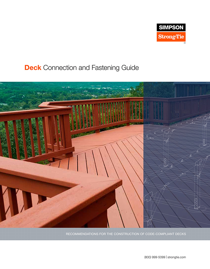
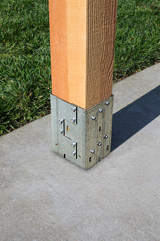
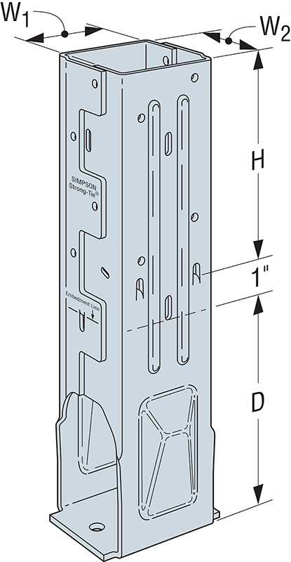
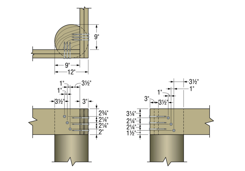
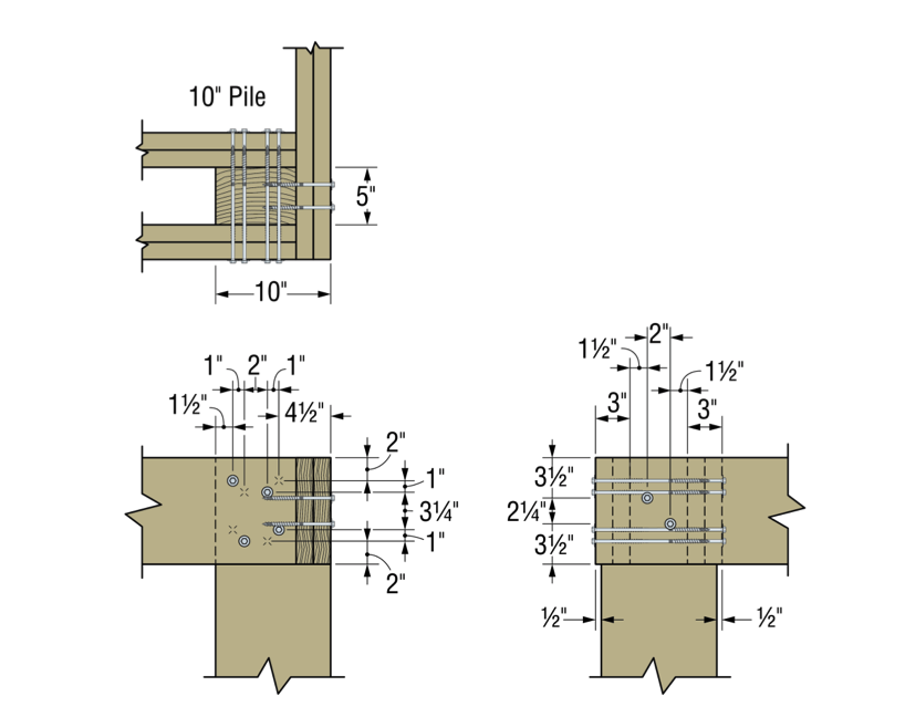
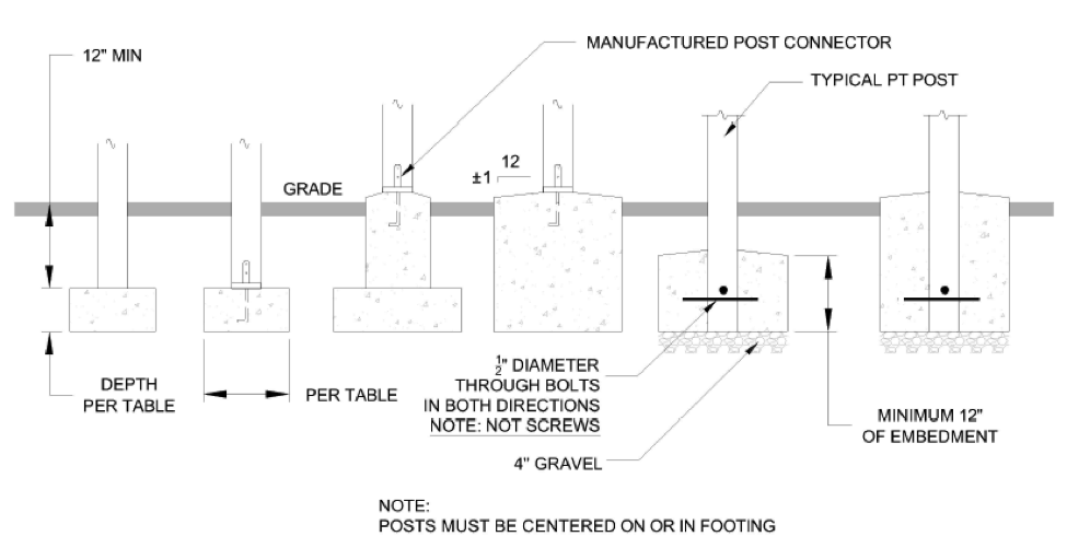
A broad group of parties interested in deck safety, known as the Deck Code Coalition, submitted 17 different code changes with revisions to Section R507 on decks. Of those, 12 were approved, making significant changes to that section. The various approved changes included the following: a complete re-write of that section; new/clarified requirements for deck materials, including wood, fasteners and connectors; clarified requirements for vertical and lateral connections of the deck to the supporting structure; new requirements for sizes of deck footings and specification that deck footings must extend below the frost line, with certain exceptions; clarification for deck board material, including an allowance for alternative decking materials and fastening methods; adding new columns to the deck joist span table that show the maximum cantilever for joists; adding the allowance for 8×8 deck posts, to allow notching for the support of a three-ply beam; and clarification of the deck-post-to-footing connection.

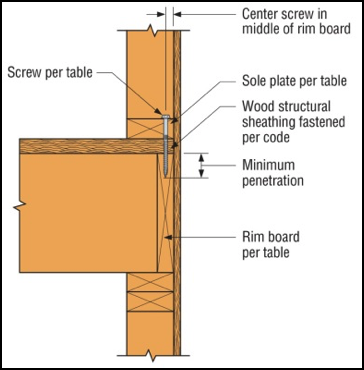
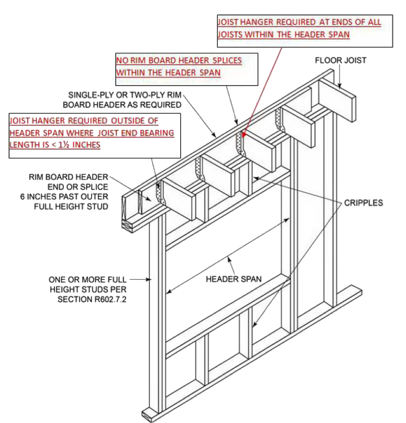
In Chapter 6, a new table permitting 11ʹ- and 12ʹ- long studs was added. In the 2015 IRC, load-bearing studs were limited to 10 feet in length. A new high-capacity nail, the RSRS (Roof Sheathing Ring Shank) nail was added as an option for fastening roof sheathing. This nail will become more widely used once the higher roof component and cladding forces from ASCE 7-16 are adopted. The rim board header detail that was added for the 2015 IRC was corrected to show that hangers are required in all cases when the joists occur over the wall opening.

There were several changes made to the Wall Bracing Section, R602.10. The use of the 2.0 increase factor was clarified for use when the horizontal joints in braced wall panel sheathing are not blocked. Narrow methods were added to the column headings for the wind and seismic bracing amount tables, to make them consistent, and the methods for adding different bracing were clarified. When using bracing method PFH, the builder can omit the nailing of the sheathing to the framing behind the strap-type holdown. Finally, offering some relief for high-seismic areas where brick veneer is used, an allowance was added to permit a limited amount of brick veneer to be present on the second floor without triggering the use of the BV-WSP bracing method.

In Chapter 8, the requirements for a “stick-framed” roof system were completely re-written to make such systems easier to use.

A couple of significant changes were made to the prescriptive requirements for cold-formed steel framing. The requirements for the anchorage of cold-formed steel walls were revised, and the wind requirements for cold-formed steel framing were changed to match the new AISI S230 prescriptive standard.

Finally, it may be helpful to mention some of the proposed changes that were not adopted. While the new ASCE 7-16 was adopted as the IRC reference standard for loads as part of the Administrative changes, several changes to the IRC to make it consistent with ASCE 7-16 were not approved. A change to update the IRC wind speed maps, roof component and cladding pressures, component and cladding roof zones, and revise the remainder of wind-based requirements to match ASCE 7-16 was not approved. Similarly, a proposal to increase the live load on decks, from 1.0 to 1.5 times the occupancy served, was denied.

Once the IRC is published, it will be time to start a new code change cycle once again, with Group A code changes due January 8, 2018. The schedule for the next cycle is already posted here.

What changes would you like to see for the 2021 codes?

What Makes Strong Frame® Special Moment Frames So Special

In a Structural Engineering Blog post I wrote last October, “Soft-Story Retrofits Using the New Simpson Strong-Tie Retrofit Design Guide,” one item I barely touched on at the time was the benefit of using Simpson Strong-Tie® Strong Frame special moment frames to retrofit vulnerable soft-story wood-framed buildings commonly found on the West Coast. In this post, I will be diving into more detail on a few features that make the Strong Frame special moment frame truly special.

In the recent release of the ANSI/AISC 358-16 (AISC 358-16), the Simpson Strong-Tie Strong Frame moment connection has been included as a prequalified special moment frame (SMF) connection.  Prequalified moment connections are structural-steel moment connection configurations and details that have been reviewed by the AISC Connection Prequalification Review Panel (CPRP) and incorporated into the AISC 358 standard. What’s unique about this newly prequalified connection is that it’s the first moment connection to be prequalified in AISC as a partially restrained (PR-Type) moment connection.

prequalified-connections

With this recent inclusion into AISC 358-16, we’ve also developed our newly released Strong Frame Design Guide  to help designers understand the differences in design and detailing between the Strong Frame connection and traditional SMF connections. The following are just a few of the key differences discussed in this guide.

SMF Yielding Elements

Traditional prequalified moment frames most often require a welded connection with either a weakened beam or a stiffened connection. SMF connections are designed so that the beam will yield as necessary under large displacements that may occur during a seismic event. The yielding of the beam section provides energy dissipation and is designed to ensure that the fully restrained beam-to-column connection isn’t compromised. The current design philosophy is the product of extensive testing of SMF connections based on studying the effects of the 1994 Northridge and 1989 Loma Prieta earthquakes in California. Figures 1, 2 and 3 below depict test specimens that demonstrate yielding at the designated areas of the beam.

special-moment-frame-development

The Strong Frame SMF has taken a different approach to the traditional connections by utilizing a Yield-Link® structural fuse designed to provide the energy dissipation for the beam-to-column moment connection. This is a modified T-Stub that has a reduced section in the stem. The yielding during a seismic event has been moved from the beams to the Yield-Link structural fuse. The fuse can be replaced after a major event, very much like an electrical fuse when overloaded. A traditional moment frame may require a much more invasive structural repair.

yielding-area-strong-frame

Beam Lateral Bracing

The traditional types of prequalified connections, as along with other proprietary connections included in AISC 358, all require the beam to yield so as to dissipate energy as discussed above. These types of connections require that the beam be braced to resist the lateral torsional buckling per code. However, it is difficult to meet the bracing requirements in the case of a steel SMF in a wood structure.

stiffness-model-beam-stability-wood-construction

With the Strong Frame SMF connection, the energy dissipation is moved from the beams to the Yield-Link structural fuses, with the connection following a capacity-based design approach. This allows the connection to remain elastic under factored load combinations. With the yielding confined to the structural fuses, inelastic deformation is not expected from the members and lateral beam buckling braces are not required. The beam can be designed to span the entire length without beam bracing. See also this blog post.

Column-Beam Relationship Requirements

Traditional SMF follow a strong column – weak beam requirement to ensure plastic hinging occurs in the beams and not the columns. If the energy dissipation takes place within such hinging in the beams, the column members will remain elastic so as to provide stability and strength for the above stories. If plastic hinges occur in the columns, there is a potential for the formation of a weak-story mechanism.

weak-story-mechanism

The Strong Frame special moment frame is unlike the traditional SMF, where the plastic hinges are formed by the buckling of the beam flange and web. In the Strong Frame SMF, the stretching and shortening of the links at the top and bottom of the Strong Frame beams are the yielding mechanisms. So instead of a strong column – weak beam check, the Strong Frame design procedure checks for a strong column – weak link condition where the ratio of the column moments to the moment created by the Yield-Link® couple is required to be greater than or equal to 1.0.

yielding-strong-frame-links

Installation

Traditional moment frame connections typically require welding in the field. Where bolted SMF connections are used, pretensioned bolts are necessary. Both welding and pretensioned bolts require third-party special inspection.

The Strong Frame SMF has been designed and tested as a 100% field-bolted connection. Unlike other bolted options, the Strong Frame’s field-bolted connections only need to be made snug tight. No onsite bolt pretensioning or special inspections are required with this system. This allows the beams and columns to be maneuvered into place, erected and installed in a fraction of the time needed for the welding, lateral-beam-bracing installation and additional inspections or repairs that traditional moment frames typically require.

T-Stub-link-installationv2

Design

One last item I’d like to discuss is the design service that Simpson Strong-Tie provides for the Strong Frame special moment frame. Whether you design moment frames only once in a while or on a regular basis, the Strong Frame design team will provide you with No-Equal design support at no additional cost. Designers receive a complete package that includes drawings and calculations, which are submittal-ready. This ensures that you’ll have a frame connection design meeting the latest codes and design requirements. Contact strongframe@strongtie.com for more information or to request design support.

To learn more about the special benefits and uses of Strong Frame moment frames, check out the following links:

Sneak Peek: Our New and Improved Deck Design Guide

One of the ways I get through winter every year is by looking forward to the weekend in March when we set our clocks ahead and “spring forward” into Daylight Savings time. Some people don’t like this change because of the lost hour of sleep, but to me it means the weather shouldn’t be cold for much longer.

The coming of spring means getting to walk to the car in daylight at the end of the workday. It also means getting the garden started for the year and spending more time outside in general.

Of course, I’m not alone in being happy to see winter go.

In the residential world, the phenomenon of “deck season” coincides with this time of year.  Homeowners with decks are getting ready for summer by giving their decks a cleaning and looking them over for any needed maintenance. Now’s the time that new or replacement decks are being planned and built to be enjoyed for the rest of the year.

deck-season

It’s no coincidence, then, that our deck-code guide has been updated again in time for warmer weather. The Deck Connection and Fastening Guide goes detail by detail (ledger connection, joist-to-beam connection, beam-to-post connection, etc.) through a typical deck and identifies the relevant building-code requirements (2012 and 2015 IRC/IBC) and connection options.

Our deck-code guide can be a helpful reference to an engineer who is just getting acquainted with decks, and can also bring you up to speed on revisions to the IRC that can necessitate engineering changes to even a relatively simple residential deck. Multilevel decks, guardrail details, ledger details and foundation challenges are all examples of things a deck builder could call you for assistance with.

For more information on resources available to engineers on deck design, feel free to consult my previous blog article, Wood-framed Deck Design Resources for Engineers.

The Deck Connection and Fastening Guide

F-DECKCODE17

This guide provides instructions on how to recognize defects and deficiencies in existing decks, and guidance for building a strong, safe, long-lasting new or renovated deck structures.


For more deck-related blog posts, check out the links below:

5 Steps to a Successful Soft-Story Retrofit

Last year, I gave a presentation at the annual National Council of Structural Engineers Associations (NCSEA) Summit in Orlando, Florida, titled “Becoming a Trusted Advisor: Communication and Selling Skills for Structural Engineers.” As this was a summit for the leaders of the structural engineers associations from across the country, I wasn’t sure how many people would find it valuable to spend their time learning about a very nontechnical topic. To my surprise and delight, the seminar ended up being standing-room only, and I was able to field some great questions from the audience about how they could improve their selling and communication skills. In the many conversations I had with the conference attendees after my presentation, the common theme was that engineers felt they needed more soft-skills training in order to better serve their clients. The problem, however, was finding the time to do so when faced with the daily grind of design work.

Structural Engineers In a Training for Seismic Retrofits
Presenting at the NCSEA Summit, I’m the tiny person in upper left hand corner.

When I started my first job as a design engineer at a structural engineering consulting firm straight out of school, I was very focused on improving and expanding my technical expertise. Whenever possible, I would attend building-code seminars, design reviews and new product solution presentations, all in an effort to learn more about structural engineering. What I found as I progressed through my career, however, was that no matter how much I learned or how hardworking I was, it didn’t really matter if I couldn’t successfully convey my knowledge or ideas to the person who really mattered most: the client.

Contractors discussing building plans with an engineer.

How can an engineer be most effective in explaining a proposed action or solution to a client? You have to be able to effectively sell your idea by understanding the needs of your client as well as any reasons for hesitation. The importance of effective communication and persuasion is probably intuitive to anyone who’s been on the sales side of the business, but not something that occurs naturally to data-driven folks like engineers. As a result of recent legislation in California, however, structural engineers are starting to be inundated with questions from a group of folks who have suddenly found themselves responsible for seismically upgrading their properties: apartment building owners in San Francisco and Los Angeles.

Imagine for a moment that you are a building owner who has received a soft-story retrofit notice under the City of Los Angeles’ Ordinance 183893; you have zero knowledge of structural engineering or what this term “soft-story” even means. Who will be your trusted advisor to help you sort it out? The City of Los Angeles Department of Building and Safety (LADBS) has put together a helpful mandatory ordinance website that explains the programs and also offers an FAQ for building owners that lets them know the first step in the process: hire an engineer or architect licensed in the state of California to evaluate the building.

Simpson Strong-Tie Structural Engineer Annie Kao at a jobsite.
Checking out some soft story buildings in Los Angeles. The Los Angeles Times has a great map tool.

I’ve had the opportunity to be the first point of contact for a building owner after they received a mandatory notice, because it turns out some relatives own an apartment building with soft-story tuck-under parking. Panicked by the notice, they called me looking to understand why they were being forced to retrofit a building that “never had any problems in the past.” They were worried they would lose rent money due to tenants needing to relocate, worried about how to meet the requirements of the ordinance and, most importantly, worried about how much it was going to cost them. What they really wanted was a simple, straightforward answer to their questions, and I did my best to explain the necessity behind retrofitting these vulnerable buildings and give an estimated time frame and cost that I had learned from attending the first Los Angeles Retrofit Resource Fair in April 2016. With close to 18,000 buildings in the cities of San Francisco and Los Angeles alone that have been classified as “soft-story,” this equates to quite a number of building owners who will have similar questions and be searching for answers.

To help provide an additional resource, Simpson Strong-Tie will be hosting a webinar for building owners in the Los Angeles area who have received a mandatory soft-story retrofit notice. Jeff Ellis and I will be covering “5 Steps to a Successful Retrofit” and helping to set a clear project path for building owners. The five steps that Simpson Strong-Tie will be recommending are:

  1. Understanding the Seismic Retrofit Mandate
  2. Partnering with Design Professionals
  3. Submitting Building Plans with the Right Retrofit Product Solutions
  4. Communicating with Your Building Tenants
  5. Completing Your Soft-Story Retrofit

We encourage you to invite any clients or potential clients to attend this informative webinar, which will lay the foundation for great communication between the two of you. As part of the webinar, we will be asking the building owners for their comments, questions and feedback so we can better understand what information they need to make informed decisions, and we will be sure to share these with the structural engineering community in a future post. By working together to support better communication and understanding among all stakeholders in retrofit projects, we will be well on our way to creating stronger and more resilient communities!

For additional information or articles of interest, there are several resources available:

Building Code Update: 2018 IBC to Reference ASCE 7-16

In early December, ICC posted the preliminary results of the Group B Online Governmental Consensus Vote, which included structural changes to the IBC, IEBC and IRC. ICC reports that there were more than 162,000 votes cast by eligible Voting Members during the three-week online voting period.

One subject of interest to building Designers, builders and some building-material suppliers was the disposition of a group of code changes that adopted ASCE 7-16 as the reference standard on loads for the IBC and IRC, and changed other parts of the IBC and IRC to reflect that.

The most controversial part of adopting the new ASCE 7-16 standard was its increase in roof component and cladding loads. The higher pressure coefficients in some cases raised the concern that the cost of roofing, roofing materials and roof repairs would be increased. Other items that raised some opposition were the new chapter on tsunami loads and the increase in deck and balcony live loads from 40 psf to 60 psf.

Despite these concerns, ICC members voted to approve the code change that adopted ASCE 7-16 as the reference for loads in the 2018 IBC, IRC and IEBC.

Along with that specific change, several other related changes were approved to correlate the IBC with adoption of ASCE 7-16. These included changes to Section 1604, General Design Requirements; adding in a new Section 1615 on Tsunami Design Requirements; modifications to Section 1613 so that seismic design requirements match ASCE 7-16; and deletion of Section 1609.6, Alternate All-Heights Method for wind design. On this last item, the argument was that since ASCE 7 now includes a simplified wind load design method, a competing method is not needed in the IBC.

Interestingly, a change to remove Strength Design and Allowable Stress Design load combinations from the IBC, which was approved by the IBC Structural Committee, was overturned and denied by the ICC Member voters. So those will remain in the IBC.

For the IRC, even though ASCE 7-16 will be shown as the referenced load standard, most changes to the actual code language relating to the new standard were denied. Items that were specifically denied included adoption of ASCE 7-16 wind speed maps, adoption of ASCE 7-16 roof pressure loading, and adoption of the new higher deck and balcony live loads. So the result is that the IBC and IRC will again be inconsistent with each other regarding wind design. On the other hand, the new USGS/NEHRP Seismic Design Maps were approved.

Future Code Corner articles will address other changes approved for the 2018 IBC and IRC.


Decrypting Cold-Formed Steel Connection Design

As published in STRUCTURE magazine, September 2016. Written by Randy Daudet, P.E., S.E., Product Manager at Simpson Strong-Tie.  Re-posted with permission. 

One of the world’s greatest unsolved mysteries of our time lies in a courtyard outside of the Central Intelligence Agency (CIA) headquarters in Langley, Virginia. It’s a sculpture called Kryptos, and although it’s been partially solved, it contains an inscription that has puzzled the most renowned cryptanalysts since being erected in 1990. Meanwhile, in another part of the DC Beltway about 15 miles to the southeast, another great mystery is being deciphered at the American and Iron Institute (AISI) headquarters.Continue Reading

New Moment-Resisting Post Base

Jhakak Vasavada

Jhalak Vasavada is currently a Research & Development Engineer for Simpson Strong-Tie. She has a bachelor’s degree in civil engineering from Maharaja Sayajirao (M.S.) University of Baroda, Gujarat, India, and a master’s degree in structural engineering from Illinois Institute of Technology, Chicago, IL. After graduation, she worked for an environmental consulting firm called TriHydro Corporation and as a structural engineer with Sargent & Lundy, LLC, based in Chicago, IL. She worked on the design of power plant structures such as chimney foundations, boiler building and turbine building steel design and design of flue gas ductwork. She is a registered Professional Engineer in the State of Michigan.

At Simpson Strong-Tie, we strive to make an engineer’s life easier by developing products that help with design efficiency. Our products are designed and tested to the highest standards, and that gives structural engineers the confidence that they’re using the best product for their application.

Installed MPBZ
Figure 1: Installed MPBZ

Having worked in the design industry for almost a decade, I can attest that having a catalog where you can select a product that solves an engineer’s design dilemma can be a huge time- and money-saving tool. Design engineers are always trying to create efficient designs, although cost and schedule are always constraints. Moment connections can be very efficient — provided they are designed and detailed correctly. With that in mind, we developed a moment post base connector that can resist moment in addition to download, uplift and lateral loads. In this post, I would like to talk about moment-resisting/fixed connections for post bases and also talk about the product design process.

Figure 2. MPB44Z Graphic

Lateral forces from wind and seismic loads on a structure are typically resisted by a lateral-force-resisting system. There are three main systems used for ordinary rectangular structures: (a) braced frames, (b) moment frames and (c) shearwalls. Moment frames resist lateral forces through bending in the frame members. Moment frames allow for open frames by eliminating the need for vertical bracing or knee bracing. Moment resistance or fixity at the column base is achieved by providing translational and rotational resistance. The new patent-pending Simpson Strong-Tie® MPBZ moment post base is specifically designed to provide moment resistance for columns and posts. An innovative overlapping sleeve design encapsulates the post, helping to resist rotation at its base.

The allowable loads we publish have what I call “triple backup.” This backup consists of Finite Element Analysis (FEA), code-compliant calculations and test data. Here are descriptions of what I mean by that.

Finite Element Analysis Confirmation

Once a preliminary design for the product is developed, FEA is performed to confirm that the product behaves as we expect it to in different load conditions. Several iterations are run to come up with the most efficient design.

Figure 3. FEA Output of Preliminary MPB Conceptual Design

Code-Compliance Calculations

Load calculations are prepared in accordance with the latest industry standards. The connector limit states are calculated for the wood-post-to-MPBZ connection and for MPBZ anchorage in concrete. Steel tensile strength is determined in accordance with ICC-ES AC398 and AISI S100-07. Wood connection strength is determined in accordance with ICC-ES AC398 and AC13. Fastener design is analyzed as per NDS. SDS screw values are analyzed using known allowable values per code report ESR-2236. The available moment capacity of the post base fastened to the wood member is calculated in accordance with the applicable bearing capacity of the post and lateral design strength of the fasteners per the NDS or ESR values. Concrete anchorage pull-out strength is determined in accordance with AC398.

Test Data Verification

The moment post base is tested for anchorage in both cracked and uncracked concrete in accordance with ICC-ES AC398.

Figure 4. Uplift Test Setup

The moment post base assembly is tested for connection strength in accordance with ICC-ES AC13.

Figure 5: Moment (induced by lateral load application) Test Set Up

The assembly (post and MPBZ) is tested for various loading conditions: download, uplift and lateral load in both orthographic directions and moment. Applicable factor(s) of safety are applied, and the controlling load for each load condition is published in the Simpson Strong-Tie Wood Construction Connectors Catalog.

Now let’s take a look at a sign post base design example to see how the MPBZ data can be used.

Design Example:

Figure 6: Sign Post Base Design Example

The MPB44Z is used to support a 9ʹ-tall 4×4 post with a 2ʹ x 2ʹ sign mounted at the top. The wind load acting on the surface of the sign is determined to be 100 lb. The MPB44Z is installed into concrete that is assumed to be cracked.

  • The design lateral load due to wind at the MPB44Z is 100 lb.
  • The design moment due to wind at the MPB44Z is (100 lb.) x (8 ft.) = 800 ft.-lb.
  • The Allowable Loads for the MPB44Z are:
    • Lateral (F1) = 1,280 lb.
    • Moment (M) = 985 ft.-lb.
  • Simultaneous Load Check:
    • 800/985 + 100/1,280 = 0.89. This is less than 1.0 and is therefore acceptable.

mpbz-deflection-evaultion

We are very excited about our new MPBZ! We hope that this product will get you excited about your next open-structure design. Let us know your thoughts by providing comments here.

Considerations for Designing Anchorage in Proximity to Abandoned Anchor Holes

danharmon.headshot.finalThis week’s post comes from Dan Harmon, an R&D engineer for Simpson Strong-Tie’s Infrastructure-Commercial-Industrial (ICI) group. Dan specializes in post-installed concrete anchor design and spent a decade managing Simpson’s anchor testing lab, where he developed extensive knowledge of anchor behavior and performance. He has a Bachelor of Science in mechanical engineering from the University of Illinois Urbana-Champaign.

Designers and engineers can spend hundreds of hours on detailed drawings of structures, but there are often conditions and coordination that can change well-planned details and drawings. As we all know, paper and reality don’t always agree. Anchorage locations can move as a result of unforeseen circumstances such as encountering reinforcing bars in an existing concrete slab or interference between different utility trades.

With post-installed anchors, one particular jobsite change may require abandoning a hole that has been drilled, leaving the final anchor location adjacent to the abandoned hole. When a hole for an anchor is drilled but never used, it essentially creates a large void in the concrete. Depending on where this void is located in relation to an installed anchor, there is potential for the capacity of that anchor to be reduced. To give guidance on this situation to specifiers, users and contractors, Simpson Strong-Tie conducted a large series of tests in their ISO 17025–accredited Anchor Systems Test Lab in Addison, Illinois.

To evaluate the effect of abandoned holes located adjacent to post-installed anchors, we performed tension tests meeting the requirements of ASTM E488-15 (see Figure 1). A variety of anchor types with common diameters were tested:

  • Drop-in anchors (1/2″ and 3/4″ diameter)
  • Wedge-type anchors (1/2″ and 3/4″ diameter)
  • Concrete screws (1/2″ diameter)
  • Adhesive anchors with threaded rod (1/2″ diameter)
Figure 1: Common Unconfined Tension Test Set-Up per ASTM E488-15

Each anchor type and diameter was tested under five different conditions:

  • No abandoned hole near the installed anchor. This is considered the reference condition to which other tests are to be compared.
  • One abandoned hole at a distance of two times the hole diameter (2d) away from the installed anchor. See Figure 2.
  • One abandoned hole at a distance of four times the hole diameter (4d) away from the installed anchor.
  • Two abandoned holes, each at a distance of two times the hole diameter (2d) away from the installed anchor. In test conditions with two holes, the holes were located on either side of the installed anchor, approximately 180º from each other. See Figure 3.
  • Two abandoned holes, each at a distance of two times the hole diameter (2d) away from the installed anchor, with the holes refilled with a concrete anchoring adhesive that was allowed to cure fully prior to testing. See Figure 4.
Figure 2: Drop-In Anchor with a Single Hole at a Distance of 2d
Figure 3: Drop-In Anchor with Two Holes at a Distance of 2d
Figure 4: Drop-In Anchor with Two Holes, Filled with Anchoring Adhesive, at a Distance of 2d

This test program is summarized in Table 1. In all cases, the abandoned hole was of the same diameter and depth as the hole prescribed for the installed anchor.

Table 1. Summary of Test Program

Five tests for each anchor under each condition were tested, and the mean and coefficient of variance of each data set were calculated. These calculated values were used to compare the different conditions.

Across the different anchor types and diameters, the test results showed a number of general rules that held true.

Summary Results

Abandoned holes that are 2” or more away from the anchor have little to no effect on the tension performance of the anchor. Compared to the reference condition with no abandoned hole near the anchor, conditions where the abandoned hole was sufficiently far away were found to be essentially equivalent. This equivalence held true even for anchor types that create expansion forces (drop-in and wedge-type anchors) during their installation.

Two abandoned holes have the same effect on performances as one, regardless of distance from the anchor. This testing showed that adding a second abandoned hole near an installed anchor did not adversely affect tension performance in a significant way. Even within distances of 2 inches, performance did not drop substantially – if at all – in conditions involving two abandoned holes as compared to one.

Filling abandoned holes with an anchoring adhesive prior to installation of the anchor improves performance. In all cases tested, filling abandoned holes with adhesives resulted in increased performance compared to leaving the holes empty. In a majority of cases, performance with filled holes was equivalent to performance in the reference condition regardless of the distance from the anchor.

When the abandoned hole is more than two times the drilled hole diameter but less than 2″from the anchor – and left unfilled – the testing showed a loss in performance. Not surprisingly, the degree of that loss was dependent on the type of anchor. Table 2 shows the capacity reduction compared to the reference condition in testing with expansion anchors. Table 3 shows the same results for concrete screws and adhesive anchors. Conservative suggested performance reductions in these conditions would be 20% for expansion anchors and 10% for concrete screws and adhesive anchors.

Table 2: Performance Reduction for Expansion Anchors
Table 3: Performance Reduction for Concrete Screws and Adhesive Anchors

In an ideal world, the engineer’s designs could be followed at all times at the jobsite. But we don’t live in an ideal world. Good engineering judgment is needed in situations where variation is required, and having data to support those decisions is always helpful. In the case of abandoned holes near post-installed anchors, it’s Simpson Strong-Tie’s hope that this testing provides additional guidance for the designer, inspector, and jobsite worker.


How do you Design Sole-Plate-To-Rim-Board Attachments?

For many years, builders have struggled with the awkward sole-plate-to-rim-board attachment. They often install a few nails and call it good, resulting in a connection with significantly less capacity than needed. This connection is critical to ensure that seismic and wind loads are adequately transferred to the lateral-force-resisting system. With screws becoming much more common in construction, we saw an opportunity to address this problem.

We offer a variety of structural wood screws that have shank diameters ranging from 0.135″ to 0.244″. They form our Strong-Drive® line of structural fasteners. The Simpson Strong-Tie® Strong-Drive SDWC Truss, SDWH Timber-Hex, SDWS Timber, SDWV Sole-to-Rim and SDS Heavy-Duty Connector structural wood screws as shown in Figure 1 can be used to attach sole plates to a rim board as shown in Figure 2. These screws provide structural integrity in the wall-to-floor connection.

The sole-to-rim connection is considered a dry service location. When the sole plate and the rim are both clean wood (not treated), then any of the screws can be used as long as they meet the design loads. However, if one or both members of the connection are treated with fire retardants or preservatives, then you must use the SDWS Timber screw, SDWH Timber-Hex screw or SDS Heavy-Duty Connector screw. The SDWS, SDWH and SDS screws all have corrosion-resistance ratings in their evaluation reports.

Figure 1. Simpson Strong-Tie Strong-Drive screws for fastening the sole-to-rim connection: (a) SDWS Timber screw, (b) SDWV Sole-to-Rim screw, (c) SDWH Timber-Hex screw, (d) SDS Heavy-Duty Connector screw, (e) SDWC Truss screw.
Figure 2. The load rating for the sole-to-rim connection is for transfer of loads parallel to the sole plate to the rim. This is a dry service condition.

The Strong-Drive SDWV structural wood screw has the smallest diameter among these screws. The SDWV is 4″ long and has a 0.135″- diameter shank, and a large 0.400″-diameter ribbed-head with a deep six-lobe recess to provide clean countersinking. It is designed to be fast driving with very low torque. The Strong-Drive SDWS offers one of the larger diameters. It has a 0.220″-diameter shank and is offered in lengths of 4″, 5″ and 6″. It has a large 0.750″-diameter washer head which provides maximum bearing area. Longer screws allow designers to meet the minimum penetration requirement into a rim board, when the sole plate is a 3x or a double 2x member.

We have tested various combinations of sole plates, floor sheathing, and rim boards. Typical test assemblies were built and tested with two (2) Strong-Drive® screws spaced at either 3″ or 6″. Results were analyzed per ICC-ES AC233, “Acceptance Criteria for Alternate Dowel-type Threaded Fasteners.” The allowable loads listed in Table 1 are based on the average ultimate test load of at least 10 tests, divided by a safety factor of 5.0, and are rated per single fastener. The results of these tests can be found in the engineering letter L-F-SOLRMSCRW16.

The evaluated sole plates include southern pine (SP), Douglas fir-larch (DF), hem-fir (HF), and spruce-pine-fir (SPF) in single 2x, 3x or double 2x configurations. Floor sheathing thicknesses are allowed up to 1 1/8″ thick. Rim boards can be LVL or LSL structural composite lumber or DF, SP, HF or SPF sawn lumber. The load rating also assumes that the floor sheathing is fastened separately and per code.

sdwc-load-tables

See strongtie.com for evaluation report information if it is needed.

As a Designer, you can specify any of these Strong-Drive screws that fit your design requirements. Please visit our website and download L-F-SOLRMSCRW16 for more details.

Good luck!

Pile Construction Fasteners – New and Expanded Applications

The majority of Simpson Strong-Tie fasteners are used to secure small, solid-sawn lumber and engineered wood members. However, there is a segment in the construction world where large piles are the norm. Pile framing is common in piers along the coast, elevated houses along the beach, and docks and boardwalks.

While the term “pile” is generic, the piles themselves are not generic. They come in both square and round shapes, as well as an array of sizes, and they vary greatly based on region. The most common pile sizes are 8 inches, 10 inches, and 12 inches, square and round, but they can be found in other sizes. The 8-inch and 10-inch round piles are usually supplied in their natural shape, while 12-inch round piles are often shaped to ensure a consistent diameter and straightness. All piles are preservative-treated.

Historically, the attachment of framing to piles has been done with bolts. This is a very labor-intensive method of construction, but for many years there was no viable fastener alternative. Two years ago, however, Simpson Strong-Tie introduced a new screw, the Strong-Drive® SDWH Timber-Hex HDG screw (SDWH27G), specifically designed for pile- framing construction needs. It can be installed without predrilling and is hot-dip galvanized (ASTM A153, Class C) for exterior applications.

Figure 1 – SDWH27G Lengths

Simpson Strong-Tie tested a number of different pile-framing connections that can be made with the SDWH27G screw. This blog post will highlight some of the tested connections. More information can be found in the following three documents on our website:

  • The flier for the SDWH Timber-Hex HDG screw: F-FSDWHHDG14 found here.
  • The engineering letter for Square Piles found here.
  • The engineering letter for Round Piles found here.

The flier provides product information, and the engineering letters include dimensional details for common pile-framing connections that were tested.

Piles are typically notched or coped to receive a horizontal framing member called a “stringer.” The coped shoulder provides bearing for the stringer and serves as a means of transferring gravity load to the pile. The SDWH27G can be used to fasten framing to coped and non-coped round and square piles.

The connections that we tested can be put into four general groups that include both round and square piles:

  • Two-side framing on coped and non-coped piles
  • One–side framing on coped and non-coped piles
  • Corner framing on coped piles
  • Bracing connections

Additionally, the testing program included four different framing materials in several thicknesses and depths:

  • Glulam
  • Parallam
  • Sawn lumber
  • LSL/LVL

The total testing program included more than 50 connection conditions that represented pile shape and size, framing material and thickness and framing orientation and details. We assigned allowable uplift and lateral properties to the tested connections using the analysis methods of ICC-ES AC13. Figures 2 and 3 show some of the tested assemblies.

Figure 2 – Uplift Test of a 10" Coped Round Pile with a 3-2x10 SYP Stringer
Figure 2 – Uplift Test of a 10″ Coped Round Pile with a 3-2×10 SYP Stringer
Figure 3 – Lateral Test of an 8" Coped Square Pile with a 3.125" Glulam Stringer
Figure 3 – Lateral Test of an 8″ Coped Square Pile with a 3.125″ Glulam Stringer

Figures 4 through 9 illustrate some of the connections and details that are presented in the flier and engineering letters.

Some elements of practice are important to the design of pile-framing connections. Some of the basic practices include:

  • For coped connections, the coped section shall not be more than 50% of the cross-section.
  • For coped connections, the coped shoulder should be as wide as the framing member(s).
  • Fastener spacing is critical to the capacity of the connection.
  • When installing fasteners from two directions, lay out the fasteners so that they do not intersect.
Figure 4 – Square and Round Two-Sided Stringers
Figure 5 – Single-Side Stringer with Notched Pile
Figure 6 – Single-Side Stringer with Unnotched Pile
Figure 7 – Round Pile Corner Condition
Figure 8 – Square Pile Corner Condition

In many cases, pile-framing connections use angled braces for extra lateral support. The SDWH27G can be used in these cases too.

Figure 9 – Braced Condition

In the flier and engineering letters previously referenced, you will find allowable loads and specific fastener specifications for many combinations of stringer and pile types and sizes.

What have you seen in your area? Let us know – perhaps we can add your conditions to our list.