Soft-Story Retrofits Using the New Simpson Strong-Tie Retrofit Design Guide

Thousands of soft-story buildings up and down the West Coast require retrofits to prevent collapse in the event of a major earthquake. Whether the retrofits are mandated by a city ordinance (as in San Francisco, Berkeley and Los Angeles) or are undertaken as voluntary upgrades, the benefits of adding necessary bracing to strengthen the ground story are immense. Simpson Strong-Tie has taken the lead, with our new Soft-Story Retrofit Guide, to provide information that helps engineers find solutions to reinforce soft-story buildings against collapse. We are also providing information on the two methods that can be used for the analysis and design of these soft story retrofits.

soft-story-retrofit-guide
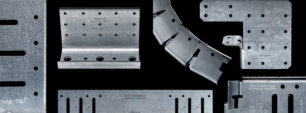
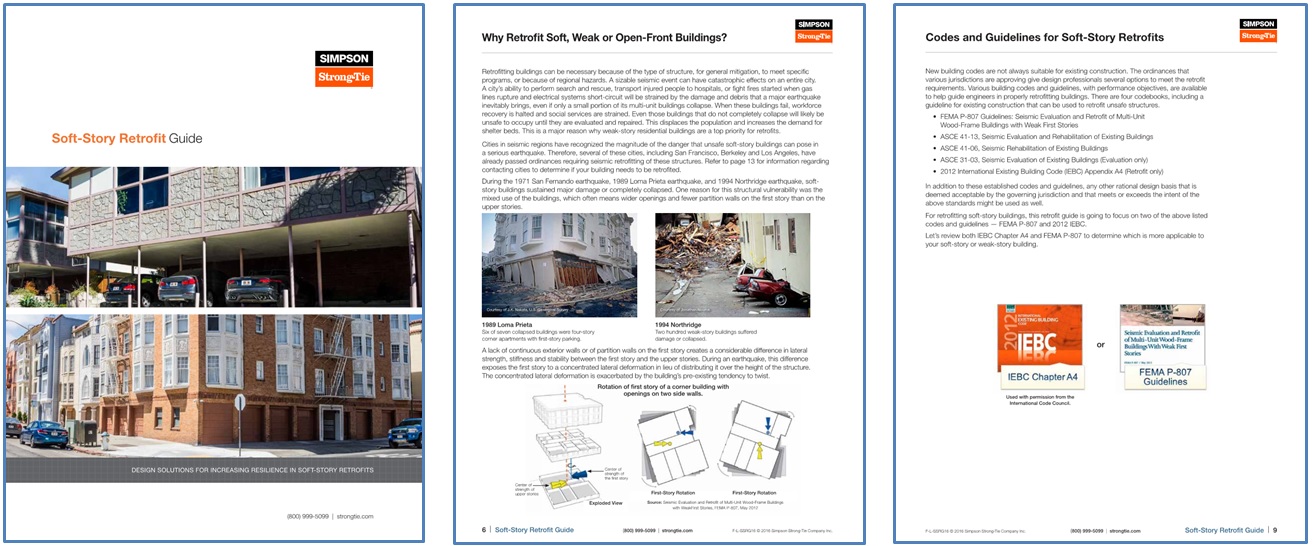
After the initial information section of the guide, a two-page illustrated spread (pp. 14–15) shows various retrofit products that could be used to retrofit the soft-story structure with reference to the following pages. Three main lateral-force-resisting systems highlighted in this graphic are the Strong Frame® special moment frame (SMF), the new Strong-Wall® wood shearwall, and conventional plywood shearwalls. Individual retrofit components are also shown, such as connection plates and straps for lateral-load transfer, anchors for attachment to the foundation, fasteners and additional products such as the RPBZ retrofit post base and AC post caps for providing a positive connection.

soft-story-product-illustration
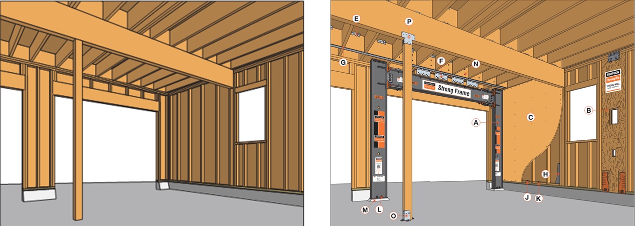
Turning the page, you come to the section describing in detail the many benefits of the Strong-Frame special moment frame (SMF) in a retrofit situation. The engineered performance of the SMF provides the additional strength and ductility that the building requires and can be fine-tuned by selecting various combinations of beams, columns, and Yield-Link® structural fuse sizes. A typical retrofit Strong Frame® SMF comes in three complete pieces allowing for the frame to be installed on the interior of the structure in tight quarters. The frame is simply installed using a 100% snug-tight field-bolted installation with no on-site welding or lateral-beam bracing required.

field-installation-beam-to-column
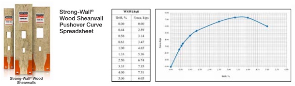
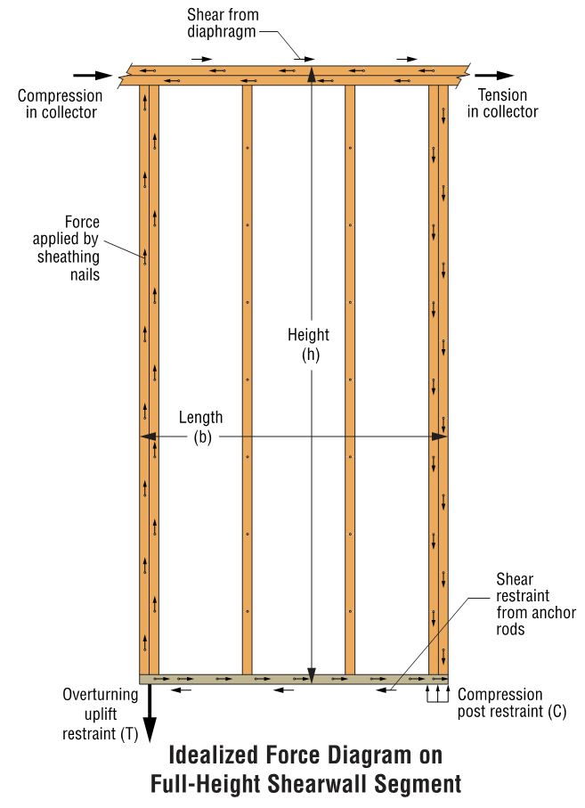
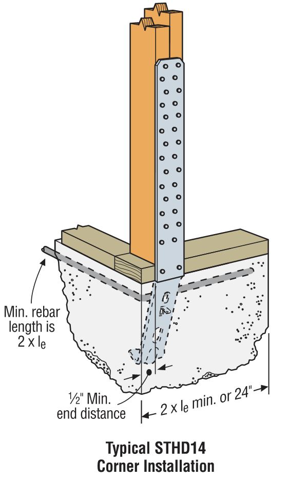
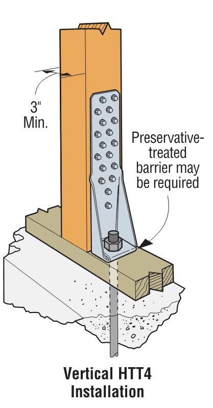
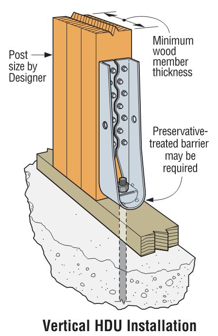
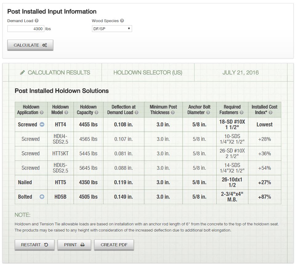
The next lateral system we focus on is the Strong-Wall® shearwall and the new grade beam solutions offered to reduce the concrete footprint. The new Strong-Wall wood shearwall includes an improved front-access holdown and top-of-wall connection plates for easier installation. Both the Strong Frame SMF and the Strong-Wall wood shearwall have load-drift curves available for use with FEMA P-807. Site-built shearwalls can be installed using retrofit anchor bolts at the mudsill and new holdowns at the shearwall end posts.

strong-wall-wood-shearwall-pushover-curve
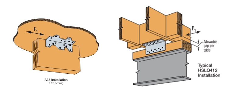
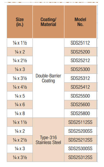
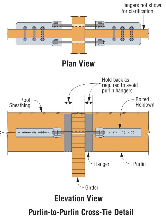
In the pages following the lateral systems, various products are shown with tabulated LRFD capacities, whereas ASD capacities are typically provided in the order literature for these products. Both ASD and LRFD capacities have been provided for products with new testing values such as the A35 and L90 angles installed with ⅝”-long SPAX screws into three different common floor sheathing materials, as well as for the new HSLQ heavy-shear transfer angle designed to transfer higher lateral forces directly from 4x blocking to the 4x nailer on the Strong-Frame SMF, even when a shim is used between the floor system and the frame. LRFD capacities are provided in this new Soft-Story Retrofit Guide specifically for use with the FEMA P-807 design methodology. This methodology specifies in section 6.5.1 that:

Load path elements should be designed to develop the full strength and the intended mechanism of the principal wall or frame elements. Therefore, to ensure reliability, appropriate strength reduction factors should be applied to the ultimate strengths of load path elements. Specific criteria may be derived from principles of capacity design or from other codes or standards, such as ASCE/SEI 41 or building code provisions involving the overstrength factor, Ωo.

FEMA P-807 bases the capacity of the retrofit elements on the peak strength. LRFD capacities are provided for various load-path connector products, which can be used to develop the full strength of the lateral-force-resisting element to satisfy this requirement.

typical-a35-hslq412-installation
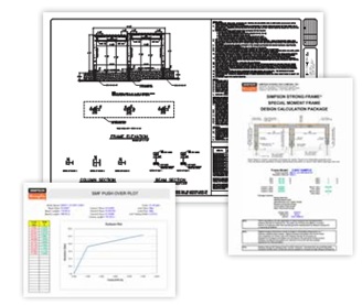
Wrapping up, the guide focuses on the various free design tools and resources available for the evaluation, design and detailing of the soft-story structure retrofit. These tools include the Weak Story Tool with Simpson Strong-Tie® Strong Frame® Moment Frames, Design Tutorials for the WST for both San Francisco– and Los Angeles–style buildings, our Soft-Story Retrofit Training Course offering CEUs, Strong Frame Moment Frame Selector Software, Anchor Designer™ Software for ACI 318, ETAG and CSA, and tailored frame solutions using our free engineering services.

soft-story-documentsFor other information regarding soft-story retrofits, refer to previous blogs in “Soft-Story Retrofits,”  “City of San Francisco Implements Soft-Story Retrofit Ordinance,” and “Applying new FEMA P-807 Weak Story Tool to Soft-Story Retrofit.”


How to Pick a Connector Series – Truss Hangers

In our second blog in the “How to Pick a Connector Series,” Randy Shackelford discussed the various considerations involved in selecting a joist hanger. So why is this blog post about truss hangers? A hanger is a hanger, right? Before I moved into the Engineering Department at Simpson Strong-Tie, I was the product manager for our Plated Truss product line. I can assure you that there is a bit more that goes into the selection (and design) of a truss hanger than does into selecting a joist hanger!

Of course, all of the considerations that were covered in the joist hanger blog apply to truss hangers as well. This blog post is going to discuss some additional considerations that come into play in selecting a hanger for a truss rather than a joist, and how some hangers have features designed especially for trusses.

The first (and most obvious) truss-specific consideration is the presence of webs. Because of truss webs, top-flange hangers are not as conducive to truss applications as they are to joist applications. A better alternative for trusses is an adjustable-strap hanger that can be installed as a top-flange hanger or face-mount hanger. Take the THA29, for example, Simpson’s first hanger developed specifically for the truss industry (circa 1984). It can accommodate different girder bottom chord depths, which eliminates the need for multiple SKUs, and the straps can be field-formed over the top of the girder bottom chord to reduce the number of fasteners (just like top-flange hangers). When a web member is in the way of the top-flange installation method, the straps can be attached vertically to the web in a face-mount installation instead.

Typical THA29 Installation

What if the web at that location isn’t vertical? You can still install the strap onto the web, but if any nails land in the joint lines formed by the intersection of the wood members, they cannot be considered effective. Therefore, the hanger allowable load may need to be reduced to account for ineffective header nails. This alternative installation is acceptable for any face-mount hanger located at a panel point as shown in our catalog (see detail below).

hgus2102-installed

Although very versatile, not all adjustable-strap hangers can be installed on all sizes of bottom chords. Our catalog specifies a C-dimension for these hangers, which corresponds to the height of the side-nailing flanges. If that dimension exceeds the height of the bottom chord, then the straps cannot be field-formed as needed for the top-flange installation. And if the hanger isn’t located at a panel point, nailing the straps to any diagonal web that the straps can reach (see photo below) is not an acceptable option!

The wrong hanger selection for the application

Another unique consideration that goes into the selection of a truss hanger is the heel height of the carried truss. A truss with a short heel height installed into a tall hanger will likely leave air (or “daylight,” as I call it) behind a lot of the nail holes running up the side flanges. When nail holes in a hanger have air behind them instead of wood, this equates to a reduction in hanger capacity. So when the carried truss has a heel height that is much less than the depth of the carrying member (and the hanger), it is important to use the appropriate hanger capacity for that condition and not overestimate the hanger’s capacity. Refer to our technical bulletin T-REDHEEL for allowable loads for reduced heel height conditions.

Example of a short heel installed in a tall hanger.

Because trusses are capable of carrying a lot of load –  and producing large reactions –  hangers for truss applications often require larger capacities than joist hangers. Unfortunately, there is only so much capacity that can be achieved from a hanger that fits entirely onto a girder truss bottom chord. Therefore, in order to use our highest load-rated truss hangers, a properly located vertical web is required, and the web must be wide enough for the hanger’s required face fasteners and minimum edge distances. The more capacity that is required, the more fasteners it takes, and the wider the vertical web must be. Our highest-load-rated truss hanger that installs with screws is the HTHGQ. It has a maximum download capacity of 20,735 lb., but it requires a minimum 2×10 vertical web. The THGQ/THGQH series can be installed onto as small as a 2×6 web, but the maximum possible capacity on a 2×6 web is 9,140 lb.

hthgq-installation

In addition to high-capacity hangers, truss applications often require high-capacity skewed hangers. When selecting skewed hangers, it’s important to realize that hangers with custom skew options usually have a reduction that must be applied to the hanger’s 90-degree capacity.  Another important factor that is sometimes overlooked in the selection of skewed hangers is whether the carried member is square-cut or bevel-cut. When the member is square cut – as in the case of trusses – not only does this typically result in a greater reduction in capacity, but some skewed hangers cannot be used at all with square-cut members. For example, the fastener holes on the side flange may not be located far enough away from the header to accommodate square-cut members. See the photo below for an example of what can happen if a skewed hanger that is intended for a bevel-cut member is used for a truss.

Incorrect hanger selection – this skewed hanger requires the carried member to be bevel-cut whereas the truss is square-cut.
Not all skewed hangers can be used with square-cut members (trusses).

As discussed in the previous hanger blog, face-mount hangers offer the advantage of being installed after the joist (or truss) is installed. What if the truss is installed prior to the hanger and a gap exists between the truss and the carrying member? In that case, the best option may be to select a truss hanger that was designed with this type of installation tolerance in mind, the HTU hanger. Other face-mount truss hangers that use double-shear nailing are great when gaps are limited to ⅛” or less, but their capacities take a pretty large hit when the gap exceeds ⅛” (see our previous blog Minding the Gap in Hangers for more information). The HTU was designed to give an allowable load for up to a ½” gap between the end of the truss and the carrying member. In addition, it has built-in nailing options to accommodate short heel heights even in the taller models – definitely a truss hanger!

HTU Hanger
HTU Hanger

Finally, there is one more thing to consider when selecting a face-mount hanger for a truss application, which relates to how tall the carrying member is compared to the hanger. Assuming the bottom of the hanger will be installed flush with the bottom of the girder bottom chord, a hanger that is much shorter than the bottom chord will induce tension perpendicular to the grain in the chord. Due to wood’s inherent weakness in perpendicular-to-grain tension, a hanger that is too short may limit the amount of load that can be transferred– to something less than the hanger’s published allowable load. Therefore, it isn’t enough to check whether the hanger fits on the bottom chord; the hanger must also cover enough depth of the chord to effectively transfer the load (or else the allowable hanger load may need to be reduced to the member’s allowable cross-grain tension limit).

Cross-grain tension is not a truss-specific issue, but because it is an explicit design provision in the truss design standard (TPI 1), it is a necessary consideration to mention in a discussion about truss hanger selection. In fact, proper detailing for cross-grain tension in different wood applications could be a future topic in and of itself.

Add to all this the specialty truss hangers that can carry two, three, four, and even five trusses framing into one location, and it is no wonder that there is an entire section in our catalog that is dedicated to truss hangers. Are there any other truss hanger needs that you would like to discuss? Please let us know in the comments below!


Bucket Lists for Structural Engineers and Some Resources for Helping Cross Post-Frame off Your List

Bucket lists are mentioned regularly today, which got me to thinking  – what about a bucket list for structural engineers? ASCE and others have put together lists of engineering wonders of the modern world, so those seem like a good start for sights to see. But for a practitioner, I’d propose the next most obvious things to add would be working with each of the common structural building materials and system types. For engineers working with buildings, the “list” would include the various types of steel, concrete, wood and masonry materials, and then the different respective building systems.

Maybe this list can also offer a refreshing perspective when you’re wading into uncharted territory; a new material or system presents the chance to cross another item off your list! For most engineers, I would guess a post-frame building will be one of the final remaining items on their list. Post-frame is rightly known for its historical origins in agricultural buildings; however, today there is more developed design information, and post-frame buildings are being built for many different uses. If you do find yourself looking at post-frame for the first time, there are a few resources to be aware of that can help guide and inform your experience.

post-frame

Post-frame buildings comprise a primary framing system of wood roof trusses or rafters that are supported by large solid-sawn or laminated lumber columns. The secondary roof purlins and wall girts support the roof and wall sheathing. The columns are either embedded into the ground or anchored to concrete piers, walls or slabs. The buildings offer efficiency in materials, construction time and costs, and energy. An engineer can design a post-frame building in compliance with the IBC, with allowances for high-wind and seismic conditions.

Two free resources that are good starting points for an engineer considering post-frame are the American Wood Council’s Design for Code Acceptance (DCA5) – Post Frame Buildings, and the Post-Frame Construction Guide by the National Frame Building Association (NFBA). The DCA5 gives a brief overview of the pertinent section of the IBC that relates to post-frame. The Post-Frame Construction Guide is a 20-page document that describes the components of a post-frame system, fire performance, examples of common details and different building uses, and a summary of resources for additional information.

A manual for purchase that is an excellent resource is the NFBA’s Post-Frame Building Design Manual – Second Edition. The manual presents a comprehensive scope of content including sections on code provisions, guidance for design, diaphragm design, post design and foundation design. Lesser-known IBC-referenced standards that are commonly utilized in post-frame, such as ASABE EP 484.2 for diaphragm design and ASABE EP 486.1 for shallow post foundation design, are covered by the manual.

What do you think of the idea of a bucket list for structural engineers? Would you already be able to cross off post-frame building from your list? Let us know by posting a comment.

How to Pick a Connector Series – Selecting Fasteners

The parts won’t hold themselves up. They have to be fastened in place.

The previous blog in the How to Pick a Connector Series by Randy Shackelford, on “ Selecting a Joist Hanger,” covered the available Simpson Strong-Tie joist hanger options and how to pick a hanger for your design. This week’s blog focuses on the fasteners recommended for various wood connectors.

For straps, holdowns and other connectors, the first step is to specify a product that meets the load and corrosion resistance requirements. Then, specify fastening that is appropriate. The Wood Construction Connectors catalog, C-C-2015, offers fastener information for every Simpson Strong-Tie connector used in wood construction. If you specify the type and number of fasteners and install them as shown in the catalog, then your installation will get full design values. Many connectors are designed to be installed with either nails or Strong-Drive® SD Connector screws. Some products must be installed with Strong-Drive SDS Heavy-Duty Connector screws. Figure 1 is a snip from page 76 of catalog C-C-2015. Here the face-mount hanger table gives the size and number of nails to be installed in the header and the joist, and the table note defines the nail size terminology. Let’s take a look at the various fasteners used for Simpson Strong-Tie connectors of all varieties.

Figure 1. A snip from the face-mount hangers table showing the size and number of nails to be used in the header and joist. The footnote defines the nail sizes in the table.

Figure 2 shows a scale view of almost all of the fasteners used with connectors. You can find this illustration in the Fastening Systems catalog, C-F-14, and the Wood Construction Connectors catalog, C-C-2015. However, we are continually designing, evaluating and adding new fasteners to use with our connectors. Check our website for the latest and greatest.

Figure 2. Fastener types and sizes specified for Simpson Strong-Tie connectors.

Keep in mind some generalities that are to be considered in every connector fastener specification.

  • Type and size – Be sure to specify the correct type of fastener and size; for nails, that means diameter and length.
  • Do not mix fasteners – Do not combine nails and screws in the same connector unless specifically allowed to do so in the load table.
  • Corrosion resistance – Consider environmental corrosion and galvanic corrosion. For environmental corrosion, specify fasteners that have corrosion resistance similar to the connector; for galvanic corrosion, the fasteners and connector should be galvanically compatible. Figure 3 shows the corrosion resistance recommendations for fasteners and connectors.
Figure 3. Corrosion resistance recommendations.

NAILS

Nail terminology is messy. In a recent Structure Magazine article (July 2016), the author made the point that nail specifications are frequently misinterpreted (or overlooked), and as a result the built system does not have the intended design capacity. In general construction vernacular, specification by penny size identifies only the length. For example, a “10d” specification could be interpreted to mean 10d common – 0.148″ x 3″, 10d box – 0.128″ x 3″, 10d sinker – 0.120″ x 2.875″, or the 10d x 2.5″ – 0.148″ x 2.5″. See NDS-12, Appendix L, Table L4 for the length, nail diameter and head diameter of Common, Box, and Sinker steel wire nails. What if the face-mount hanger needed 0.148”x3” nails to achieve full load, but the face-mount hanger was installed with 0.148″ x2.5″?  In this case, the nail substitution causes a reduction in load capacity of 15%. The load capacity losses would be even greater if 10d sinker or 10d box nails were used. The load adjustment factors for nail substitutions used with face- mount hangers and straight straps are shown in Table 3.

Simpson Strong-Tie nail terminology further complicates nail specification because, in Strong-Tie lingo, the penny reference is to diameter (not to length). This is further reason to write nail specifications in terms of diameter and length.

The best way to prevent mistakes is to specify nails by both length AND diameter.

There are two types of connector nails available, the Strong-Drive® SCNR Ring-Shank Connector nail and the Strong-Drive SCN Smooth-Shank Connector nail. SCN stands for Structural Connector Nails. R would refer to ring- shank nails. Currently most ring-shank connector nails are available in Type 316 stainless steel. Reasons for this are discussed here. The smooth-shank nails are made of carbon steel and either have a hot-dip galvanized (HDG) finish meeting the specifications of ASTM A153, Class D, or have a bright finish. Stainless-steel ring-shank nails are recommended for stainless-steel connectors. Use hot-dip galvanized nails with ZMAX® and HDG connectors. See Table 1 for the nail properties.

Table 1. Simpson Strong-Tie® connector nail terminology decoder. The penny size refers to diameter and “N” indicates a short nail.

Simpson Strong-Tie connector nail specifications include common nails, sinker nails and short nails. Nails used in connectors should always have a full round head and meet the bending yield requirements of ASTM F1667, Table S1. Nails can be driven with a hammer or power-driven. Table 2 shows the Strong-Tie connector nails by catalog name, size and model number.

Table 2. Simpson Strong-Tie® Strong-Drive® SCN and SCNR Connector nails. HDG is hot-dip galvanized per ASTM A153, Class D; EG is electro-galvanized per ASTM B641, Class 1; SS is Type 316 stainless steel; “A” indicates ring-shank. These are collated for power-tool nailing in paper tape (PT).

Remember that connector double-shear nailing should always use full-length common nails. Do not use shorter nails in double-shear conditions.

Table 3 is snipped from the Fastening Systems catalog, and it shows load adjustment factors for optional fasteners used in face-mount hangers and straps.

Table 3. From the Fastening Systems catalog, C-F-14. Load adjustment factors and footnotes.

SD Screws

Figure 4. SD9112 CONNECTOR Screw.

Almost 150 Simpson Strong-Tie connectors can be installed with Simpson Strong-Tie Strong-Drive® SD Connector screws (Figure 4). The shanks of the SD Connector screws are designed to match the fastener holes in Simpson Strong-tie connectors. The screw features, dimensions, strengths and allowable single-fastener properties are given in ICC-ES ESR-3046, and the SD screws have been qualified for use in engineered wood products. See ICC-ES ESR-3096 for code-approved connectors installed with SD screws.

SD screws can make connector and strap installation easier and can also provide some resistance that is needed beyond what might be offered by nails. Ease of installation is sometimes an issue in tight places where it might be much easier to use a screw-driving tool rather than a hammer or a power nailer. Some installations are improved by using screws instead of nails, especially where pulling away from the mounting member is a possible failure mode. For example, joist hangers for a deck need withdrawal resistance to help keep the deck tightly connected to the ledger.

SD screws are available in four sizes as shown in Table 4 below. These screws are mechanically galvanized per ASTM B695, Class 55, and have corrosion-resistance qualifications for use in chemically treated wood for Exposure Conditions 1 and 3 per ICC-ES AC257, which is the acceptance criterion for Corrosion-Resistant Fasteners and Evaluation of Corrosion Effects of Wood Treatment Chemicals. See ICC-ES ESR-3046 for corrosion resistance details. Visit SD Screws in Connectors for a complete list of connectors that can be installed with SD screws.

Table 4. SD Connector Screws.

Here are a few specification and construction tips for SD screws:

  • SD10 screws replace 16d common and N16 nails in face-mount hangers and straps.
  • SD9 screws replace 8d and 10d common and 1-1/2″ size nails and 16d sinker nails (all nails 0.148″ and 0.131″ diameter) in face-mount hangers and straps.
  • When SD screws are to be an alternative to nails, specify and use only SD screws. Other types of screws shall not be substituted.
  • SD screws are required to be installed by turning. Do not drive them with a hammer or palm nailer!
  • SD screws and nails cannot be mixed in the same connector.

SDS Screws

Figure 5. Strong-Drive® SDS HEAVY-DUTY CONNECTOR Screw.

The Simpson Strong-Tie Strong Drive® SDS Heavy-Duty Connector screws are 1/4″ screws with a hex washer head (Figure 5). They are available in nine lengths. Table 5 shows the available SDS screws. SDS Screws are available with a double-barrier coating or in Type 316 stainless steel. These screws can be installed with no predrilling and have been extensively tested in various applications. SDS screws can be used for both interior and exterior applications. See ICC-ES ESR-2236 for dimensions, mechanical properties and single-fastener allowable properties. As shown in the evaluation report, SDS screws are also qualified for use in chemically treated wood. See the evaluation report for particulars. SDS screws also have been qualified for use in engineered wood products.

Table 5. SDS Heavy-Duty Connector Screws.

If you need more information about the nails and screws recommended for use with Simpson Strong-Tie connectors, visit strongtie.com and see the appropriate catalog, flier or engineering letter. Remember, your choice of fasteners affects the load capacity of your connections.

Let us know if you have any comments on Simpson Strong-Tie fasteners for straps, holdowns and other connectors.


Concrete Anchorage for ASD Designs

One of the first things I learned in school about using load combinations was that you had to pick either Load and Resistance Factor Design (LRFD)/Strength Design (SD) or Allowable Stress Design (ASD) for a building and stick with it, no mixing allowed! This worked for the most part since many material design standards were available in a dual format. So even though I may prefer to use LRFD for steel and ASD for wood, when a steel beam was needed at the bottom of a wood-framed building that was designed using ASD load combinations, the steel beam could easily be designed using the ASD loads that were already calculated for the wood framing above since AISC 360 is a dual- format material standard. And when the wood-framed building had to anchor to concrete, ASD anchor values were available in the IBC for cast-in-place anchors and from manufacturers for post-installed anchors in easy-to-use tables, even though ACI 318 was not a dual-format material standard. (Those were good times!)

Then along came ACI 318-02 and its introduction of Appendix D – Anchoring to Concrete, which requires the use of Strength Design. The 2003 IBC referenced Appendix D for Strength Design anchorage, but it also provided a table of ASD values for some cast-in-place headed anchors that did not resist earthquake loads or effects. This option to use ASD anchors for limited cases remained in the 2006, 2009 and 2012 codes. In the 2015 IBC, all references to the ASD anchor values have been removed, closing the book on the old way of designing anchors.

ICC-ES-equation-tension
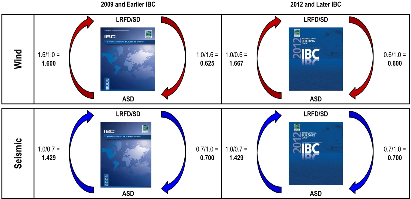
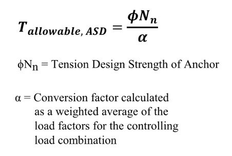
So what do you do now? Well, there is some guidance provided by ICC-ES for manufacturers to convert calculated SD capacities to ASD allowable load values. Since there is no conversion procedure stated in the IBC or referenced standards, designers may want to use this generally accepted method for converting anchor capacities designed using ACI 318. ICC-ES acceptance criteria for post-installed mechanical and adhesive anchors (AC193 and AC308) and cast-in-place steel connectors and proprietary bolts (AC398 and AC399) outline a procedure to convert LRFD capacities to ASD using a weighted average for the governing LRFD/SD load combination. So if the governing load combination for this anchor was 1.2D + 1.6L and the dead load was 1,000 pounds and the live load was 4,000, then the conversion factor would be (1.2)(0.2) + (1.6)(0.8) = 1.52 (keep in mind that the LRFD/SD capacity is divided by the conversion factor in the ICC-ES equation shown here for tension).

Right away, there are a few things that you may be thinking:

  1. What about load factors that may exist in ASD load combinations?
  2. It may just be easier to just recalculate my design loads using LRFD/SD combinations!
  3. The resulting allowable loads will vary based on the load type, or combination thereof.
  4. If the ACI 318 design strength is limited by the steel anchor, then the conversion will result in an allowable load that is different from the allowable load listed for the steel element in AISC 360.

Let’s take a look at these objections one by one.

Item 1: Since unfactored earthquake loads are determined at the ultimate level in the IBC, they have an LRFD/SD load factor of 1.0 and an ASD load factor less than 1.0, which is also true for wind loads in the 2012 and 2015 IBC (see graphic below). Using the LRFD/SD load factor of 1.0 obviously does not convert the capacity from LRFD to ASD so you must also account for ASD load factors when calculating the conversion factor. To do so, instead of just using the LRFD load factor, use the ratio of LRFD Factor over ASD Factor. So if the governing load combination for an anchor was 0.9D + 1.0E and the dead load was 1,000 pounds and the seismic load was 4,000, then the conversion factor would be (0.9)(0.2) + (1.0/0.7)(0.8) = 1.32.

ICC-ES-equations

Item 2: Even though the weighted average conversion requires you to go back and dissect the demand load into its various load types, often this can be simplified. ICC-ES acceptance criteria permit you to conservatively use the largest load factor. The most common application I run into is working with ASD-level tension loads for wood shearwall overturning that must be evaluated using SD-level capacities for the concrete anchorage. Since these loads almost always consist of wind or seismic loads, using the largest factor is not overly conservative. Depending on the direction in which you are converting the demand loads or resistance capacities, the adjustment factors are as shown in the figure below. Affected Simpson Strong-Tie products now have different allowable load tables for each load type. (For examples, see pp. 33-36 of our Wood Construction Connectors catalog for wind/seismic tables and pp. 28-30 of our Anchoring and Fastening Systems catalog for static/wind/seismic tables.)

IBC-ealier-later

Item 3: I am unsure whether there is any sound rationale for having allowable loads for an anchor resisting 10% dead load and 90% live load differ from those of an anchor that resists 20% dead load and 80% live load. Perhaps a reader could share some insight, but I just accept it as an expedience for constructing an ASD conversion method for a material design standard that was developed for SD methodology only.

Item 4: We have differing opinions within our engineering department on how to handle the steel strength component of the various SD failure modes listed in ACI 318. Some believe all SD failure modes in ACI 318 should be converted using the load factor conversion method. I side with others who believe that the ASD capacity of a steel element should be determined using AISC 360. So when converting SD anchor tension values for a headed anchor, I would apply the conversion factor to the concrete breakout and pullout failure modes from ACI 318, but use the ASD steel strength from AISC 360.

Finally, I wanted to point out that the seismic provisions in ACI 318, such as ductility and stretch length, must be considered when designing anchors and are not always apparent when simply converting to ASD. For this reason, I usually suggest converting ASD demand loads to SD levels so you can use our Anchor Designer™ software to check all of the ACI 318 provisions. But for some quick references, we now publish tabulated ASD values for our code-listed mechanical and adhesive anchors in our C-A-2016 catalog —  just be sure to read all of the footnotes!

A Tale of Two Houses: Design Loads for Metal Plate Connected Wood Trusses

two-houses-trusses

Take two trusses with identical profiles and environmental surroundings, and they should have the same design loads, right? Early in my career, I recall hearing a story about two identical buildings right next to each other that were designed for two different magnitudes of environmental loads. I remember wondering – how do the loads know which building is which?

There used to be a time when it was not uncommon for 5 substantially different wood truss designs to come from 5 different companies – all designing to the exact same spec.  Whereas some differences are always to be expected (manufacturer-specific plate design values and proprietary analogues come to mind), the truss design disparities that used to exist from one company to the next were compounded by variations in something which really shouldn’t vary at all – the application of the specified loads to the truss. Differences in loading can occur whenever there is room for interpretation. In cases where the loading specs for fabricated wood trusses are not very detailed, there is a lot of room for interpretation. And when that happens, everyone knows how many different answers you get when you ask 5 different engineers!

IBC-2012-ASCE

Fortunately, the truss industry has come a long way in this area. In some cases, the codes and standards that govern the loading of structures have improved and helped the cause. But the truss industry also made a concerted effort to minimize these loading differences. Everyone agreed that a truss bid shouldn’t be won based on “less loading,” so they set out to change that. One of the best efforts in accomplishing this was the development of the SBCA Load Guide entitled “Guide to Good Practice for Specifying & Applying Loads to Structural Building Components.” Produced by the Structural Building Component Association (SBCA) in cooperation with the Truss Plate Institute (TPI), the Load Guide was developed with the stated goal of “helping everyone that uses it to more easily understand, define and specify all the loads that should be applied to the design of each structural building component” and “to help assure that all trusses will be designed using a consistent interpretation and application of the code.”

If you are an architect, engineer or a Building Code Official who deals with trusses and you don’t already have the current SBCA Load Guide, I strongly encourage you to check it out (free downloads are available from the SBCA website here.) When fielding questions about loading on trusses, I inevitably refer the inquiring party to the SBCA Load Guide not only for the answer to the question, but for future reference as well. The SBCA Load Guide isn’t just a handy reference to read, it also offers a spreadsheet tool that can be used to calculate loads as well as output the load calculation worksheets. The worksheets can be submitted with the construction documents for plan approval or submitted to the truss manufacturer to be used in the design process.

Worksheet from the SBCA Load Guide

In addition to providing all of the code and standard loading provisions that apply to metal-plate-connected wood trusses, the SBCA Load Guide also presents the truss industry’s consensus positions and interpretations on provisions that are either unclear as to how they apply to trusses or that have resulted in loading inconsistencies in the past. With the many truss-specific examples and applications covered, it leaves very little room, if any, for further interpretation or question as to how the various code provisions should be applied to trusses.

Take wind loads, for example. Wind loading on trusses has been a heavily debated topic over the years, such as whether a truss should be designed for Components & Cladding (C&C), Main Wind Force Resisting System (MWFRS) or both. In fact, wind loading used to be one of the main sources of inconsistencies in truss designs from one company to another.  The truss industry has since established a consensus position on this matter and the SBCA Load Guide presents it as follows:

SBCA-load-guide-consensus

The SBCA Load Guide also pulls information from a variety of resources to help provide more insight into some of the code provisions. For example, in the wind loading section a graphic is reproduced from a Structural Engineers Association of Washington’s handbook (SEAW RSM-03) to clarify the effect of wind directionality on C&C wind pressures for gable/hip roofs, since this consideration is not made clear in ASCE 7.

Graphic from SEAW RSM-03 As Reprinted in the SBCA Load Guide

This clarification is further illustrated in the example wind loading diagrams, which show how wind pressures are evaluated when taking the directionality of the wind into account, i.e., by evaluating the pressures separately with the wind from the left and from the right.

Example Wind Loading Diagrams in the SBCA Load Guide

Of course, the SBCA Load Guide is only a guide and is NOT intended to supersede a Building Designer’s design specification. As specified in ANSI/TPI 1, the Building Designer is responsible for providing all applicable design loads to be applied to the trusses:

ANSI-TPI1-text

If you are an architect or engineer who specifies detailed loading schedules for truss systems, great!  Your specifications may not need the SBCA Load Guide to ensure that the trusses are accurately loaded as intended in the design of the building. But the SBCA Load Guide still provides a lot of insight as to how the truss industry – and anyone who uses the Load Guide – applies various code provisions to trusses. It might even be an interesting study to see how your specified loads compare to the loading examples in the SBCA Load Guide.

wind-zone-diagram

For everyone else who isn’t well-versed in the application of code provisions to wood trusses, the SBCA Load Guide is an invaluable tool. Building Designers, building code officials, truss technicians and truss Designers can all benefit from the Load Guide. As stated in the SBCA Load Guide, one of the industry’s goals is to achieve a greater level of consensus among the largest audience possible on how to load trusses and other structural building components. The more people who read and use the SBCA Load Guide, the more consistency there will be in the interpretation and application of code provisions pertaining to wood trusses, which will help make projects run smoother and most importantly, improve building safety. At Simpson Strong-Tie, we are big fans of tools that work to do that.

If you’ve had experience using the SBCA Load Guide, we’d love to hear about it – please let us know in the comments below!


How to Select a Connector Series – Holdowns

Keith Cullum started off our “How to Select a Connector” series with Hurricane Ties. This week we will discuss how to select holdowns and tension ties, which are key components in a continuous load path. They are used to resist uplift due to shearwall overturning or wind uplift forces in light-frame construction. In panelized roof construction, holdowns are used to anchor concrete or masonry walls to the roof framing.

shearwall-segment

Holdowns can be separated in two basic categories – post-installed and cast-in-place. Cast-in-place holdowns like the STHD holdowns or PA purlin anchors are straps that are installed at the time of concrete placement. They are attached with nails to wood framing or with screws to CFS framing. After the concrete has been placed, post-installed holdowns are attached to anchor bolts at the time of wall framing. The attachment to wood framing depends on the type of holdowns selected, with different models using nails, Simpson Strong-Tie® Strong-Drive® SDS Heavy-Duty Connector screws or bolts.

A third type of overturning restraint is our anchor tiedown system (ATS), which is common in multistory construction with large uplift forces. I discussed the system in this blog post.

methods-of-overturning-restraintGiven the variety of different holdown types, a common question is, how do you choose one?

For prescriptive designs, such as the IRC portal frame method, the IRC or IBC may require a cast-in-place strap-style holdown. Randy Shackelford did a great write-up on the PFH method in this post.

For engineered designs, a review of the design loads may eliminate some options and help narrow down the selection.

Holdown TypeMaximum Load (lb.)
Cast-in-Place5,300
Nailed5,090
SDS Screws14,445
Bolted19,070

sthd-installation

htt-installation

hdb-installation

hdu-installation

I like flipping through catalog pages, but our Holdown Selector App is another great tool for selecting a holdown to meet your demand loads. Select cast-in-place or post-installed, enter your demand load and wood species, and the application will list the holdown solutions that work for your application.

holdown-selector-app

The application lists screwed, nailed and bolted solutions that meet the demand load in order of lowest installed cost, allowing the user to select the least expensive option.

Adjustability should be considered when choosing between a cast-in-place and a post-installed holdown. Embedded strap holdowns are economical uplift solutions, but they must be located accurately to align with the wood framing. If the anchor bolt is located incorrectly for a post-installed holdown, raising the holdown up the post can solve many problems. And anchors can be epoxied in place for missing anchor bolts.

offset-holdown-raised-off-sillWe are often asked if you can double the load if you install holdowns on both sides of the post or beam. The answer is yes, and this is addressed in our holdown general notes.

notes-on-doubling-loads

Nailed or screwed holdowns need to be installed such that the fasteners do not interfere with each other. Bolted holdowns do not need to be offset for double-sided applications. Regardless of fastener type, the capacity of the anchorage and the post or beam must be evaluated for the design load.

double-sided-bolted-purlin-cross-tie

double-sided-hdu-offset-installation

Once you have selected a holdown for your design, it is critical to select the correct anchor for the demand loads. Luckily, I wrote a blog about Holdown Anchorage Solutions last year. What connector would you like to see covered next in our series? Let us know in the comments below.

Firewalls for Wood Construction

What is a firewall?

A firewall is a term that is used in the construction industry to describe a fire-resistive-rated wall or fire-stop system, which is an element in a building that separates adjacent spaces to prevent the spread of fire and smoke within a building or between separate buildings. A firewall is actually one of three different types of walls that can be used to prevent the spread of fire and smoke.

 Types of fire-resistive-rated walls: 

 The three types of fire-resistive-rated walls are firewalls, fire barriers and fire partitions. They are listed in order from the most stringent requirements to the least. A firewall is a fire-resistive-rated wall having protected openings, which restricts the spread of fire and extends continuously from the foundation to or through the roof with sufficient structural stability under fire conditions to allow collapse of construction on either side without collapse of the wall. A fire barrier is a fire-resistive-rated wall assembly of materials designed to restrict the spread of fire which continuity is maintained.  A fire partition is a vertical assembly of materials designed to restrict the spread of fire in which openings are protected.  Each type has varying requirements and the table below displays some of the differences between them.

fire-resistive-rated-wallsWhat are some of the typical uses of each type of fire-resistive wall? 

As the requirements for each type of wall vary, so do the uses. Typical uses of each are as follows:

  • Firewalls – party walls, exterior walls, interior bearing walls
  • Fire barriers – shaft enclosures, exit passageways, atriums, occupancy separations
  • Fire partitions – corridor walls, tenant space walls, sleeping units within the same building

How do you determine whether your wood building design needs a firewall?

The 2012 International Building Code (the IBC, or “the Code” in what follows), which is adopted by most building departments in the United States, is the resource we are using in this discussion. (As a side note, it’s possible your city or county has supplemental requirements, and it is best to contact your local building department for this information up front.)

To determine your fire-resistive wall requirements, review these chapters in the 2012 IBC:

  • Chapter 3, Identify Occupancy Group – typically Section 310 (“Residential Group”) for wood construction
  • Chapter 5, Select Construction Type – Section 504, Table 503
  • Chapter 6, Determine Fire-Resistive Rating Requirements – Table 601, typically Type III wood-constructed buildings require a two-hour fire separation for the exterior bearing walls

What are typical fire-resistive wall designs? 

 Information for one-hour, two-hour designs, etc. can be found in tables 721.1(2) and 721.1(3) of the Code provide information to obtain designs that meet the rating requirements (in hours) for your building, including the walls and floor/roof systems. The GA-600 is another reference that the Code allows if the design is not proprietary.

How do I know whether the structural attachments I specify for the wall and roof assemblies meet the Code requirement?

Once the wall or floor/roof assembly design is selected, the Designer must ensure that the components of the wall do not reduce the fire rating. The Code requires that products which pierce the membrane of the assemblies at a hollow location undergo a fire test to ensure they meet the requirements of the design. ASTM E814 and ASTM E119 are the standards governing the fire tests for materials and components of the fire-resistive wall. There are several criteria that the component in the assembly must meet: a flame-through criterion, a change-in-temperature criterion and a hose-stream test.

Simpson Strong-Tie has created the DHU hanger for use with typical two-hour fire-resistive walls for wood construction.The DHU hanger has passed the ASTM E814 testing and can be used on a fire-resistive wall of 2×4 or 2×6 constructions and up to two 5/8″ layers of gypsum board. The DHU and DHUTF have both an F (Fire) and a T (Temperature) rating.

dhutf-dhu-hangersThe DHU/DHUTF hanger has two options, a face-mount version (DHU) and a top-flange version (DHUTF).  The hanger doesn’t require any cuts or openings in the drywall, which ensures reliable performance; no special inspection is required.  To install the hanger, gypsum board must first be installed in a double or single layer, at least as deep as the hanger.  For installation, apply a two-layer strip of Type X drywall along the top of the wall, making the base layer a wider strip (bottom edge is 12″ or more below the face layer, depending on jurisdiction).  Then install ¼” x 3½” Simpson Strong-Tie Strong-Drive® SDS screws through the hanger and into top plates of the wall.  Since the hanger is more eccentric than typical, the top plates of the wall must be restrained from rotation. The SSP clip can be used for restraint, but the design may not require it if there is a sufficient amount of resistance already in place, such as sheathing, a bearing wall above, or a party wall as determined by the designer.  See the photos and installation illustration below for guidance or visit our website for further information.

typical-installation-over-2-layers-drywall


DoD-Compliant CFS Wall Framing Design

Back in the year 2000, the U.S. Department of Defense (DoD) was charged with incorporating antiterrorism protective features into the planning, design and execution of its facilities. The main document developed to meet this requirement is the Unified Facilities Criteria “DoD Minimum Antiterrorism Standards for Buildings” (UFC 4-010-01). The current version was published in October 2013. This document covers what is most commonly referred to as “blast” design.Continue Reading

Construction Referees: Evaluation Processes for Alternative Building Products

construction-referee
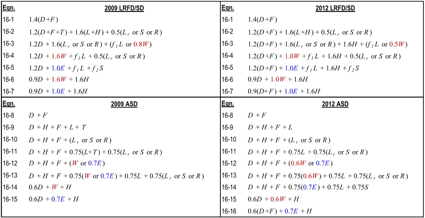
There are products used in every building not referenced by the codes or standards.
These products can impact safety, public health and general welfare through their effect on structural strength, stability, fire resistance and other building performance attributes. I-code Section 104.11 (Alternative materials, design, and methods of construction and equipment) provides guidance on how these products are approved for use in the built environment and identifies the Building Official as the decision-maker. This is similar to a referee determining a player’s compliance with the rules.

Building Officials see submittals for a wide variety of alternative building products ranging from the simple to the very complex. The amount of data included in these submittals and their relevance and completeness varies significantly from insufficient and minimal to complete and very thorough. In the absence of publicly developed and majority-approved provisions, the Building Official is tasked to ensure the data provided is appropriate and adequately proves the alternative product meets code intent to protect public safety, no matter the product type or complexity. This is compared to the robust code and standards process in which committees with balanced representation publicly develop and deliberate on provisions in order to protect public safety. The question arises whether the 104.11 requirement implies that a similar robust process be used in the development of test and evaluation requirements for alternative products as is used for the development of code and standard provisions where there is public debate, resolution of negative opinions and a majority approval of the requirements. Requiring a similar code development process for alternative products would seems to make sense. Otherwise, a less rigorous process might be employed by those seeking to avoid a more robust code and standard process so as to achieve quicker and less stringent approval for their alternative products.

public-safetySome may argue that having to use a “code-like” evaluation process for alternative products would add too much of a burden in time and cost, and that it’s not necessary since individual registered design professionals and building officials have enough time, resources and expertise to determine acceptability. But this begs the question of why a similar public majority-approval process should not be required for new products as it is required for code-referenced products. Another question that comes up is ongoing acceptance of an alternative product, as their manufacture may have changed since their approval. Additionally, different jurisdictions have different expertise and resources and this can lead to different standards for approval for alternative products, leading to inconsistency.

Is there a solution which balances providing innovative and cost-effective alternative building product solutions to the industry in a timely manner with providing a thorough product assessment using a process similar to the codes and standards to better ensure consistency and public safety? Accredited building product certification companies, or evaluation service companies, that use a publicly developed and majority-approved acceptance or evaluation criteria and publish an evaluation report with the product’s description, design and installation requirements and limitations provide such a solution. These evaluation service companies are a third-party resource for building officials to assist in their determination of whether an alternative product meets code intent and should be approved for use in their jurisdiction.

The number of evaluation service companies has been increasing. The ICC Evaluation Service and the IAPMO Uniform Evaluation Service, two of the better-known such companies, are both ANSI accredited to ISO/IEC 17065 (Conformity Assessment – Requirements for bodies certifying products, processes, and services) to provide building-code product certifications (ICC-ES, IAPMO UES). However, accreditation by itself mainly verifies a certain process is implemented to ensure consistency and confidentiality. Both companies also have a public acceptance or evaluation criteria process. This process includes an evaluation committee made up of building enforcement officials. These officials evaluate the proposed criteria, listen to expert and industry input and only approve the criteria by a majority vote if products evaluated to those criteria will meet code intent. This is similar to how the codes and standards are developed — a transparent public process and a majority approval of requirements and not just an opinion of one or a couple of individuals.

The alternative building product review process for ICC-ES and IAPMO UES is similar and has the following important components.

  • CRITERIA: The accredited product evaluation service develops an acceptance or evaluation criteria, with the manufacturer’s and public’s input, that is publicly debated, revised and ultimately approved by a majority vote of a committee of building enforcement officials.
  • TESTING: The manufacturer contracts out to an accredited independent third-party test laboratory to either perform or witness the product testing in accordance with the criteria.
  • REVIEW: Registered design professionals with the accredited product evaluation service evaluate the testing and analyses performed and sealed by registered design professionals with the manufacturers or their representatives. The product evaluation service then publishes the evaluation report to their website, and the report typically contains the product description, design and installation requirements andsupervising-supervisorlimitations.
  • CONTINUOUS COMPLIANCE: The manufacturer’s quality system is inspected at least annually by the product evaluation service or an accredited third-party
    inspection agency to ensure that the product currently being manufactured is the same as that which was evaluated.


ICC-ES-ESR-2320-UES-AT-XP

While the term “product evaluation” is sometimes used, it is often “product certification” or “product conformity assessment.” ISO/IEC Guide 2:2004 defines “conformity assessment” as “Any activity concerned with determining directly or indirectly that relevant requirements are fulfilled. Some “product certification” companies also provide “product listing” services for when testing and evaluation requirements for the product are already in code-referenced consensus standards, making the development of acceptance criteria unnecessary, thus simplifying the process.

A couple of previous blog posts on evaluation or code reports that you may find informative discuss steps to obtain an evaluation or code report and provide a checklist to determine adequacy of a report.

A mechanism is available to the building industry to provide innovative and cost-effective alternative building products in a timely manner that implements a public and majority product acceptance criteria process, similar to the codes and standards development process. This solution involves the Building Official referencing building product evaluation service reports, based on acceptance criteria, offering a robust evaluation better ensuring that an alternative product meets code intent, thus protecting the public. In fact, several jurisdictions do require evaluation service reports for alternative products.

Should there be an easier path to approval for alternative products than for code-referenced products? What is a reasonable path to product approval? What basis do you use in reviewing evaluation or code reports to determine whether an alternative product is “in or out of -bounds”? We’d love to hear your thoughts.