Revisiting Spanning the Gap

Three years ago, we created this blog post based on a technical support question we often receive about allowable fastener loads for ledgers to wood framing over gypsum board. Given that this is still a frequent question and a relevant topic, we decided to revisit the post and update it.

Drywall. Wall board. Sheetrock. Sackett Board? A product called Sackett Board was invented in the 1890s, which was made by plastering within wool felt paper. United States Gypsum Corporation refined Sackett Board for several years until 1916, when they developed a new method of producing boards with a single layer of plaster and paper. This innovation was eventually branded SHEETROCK®. More details about the history of USG can be found here.

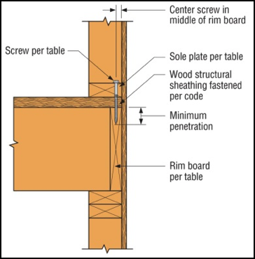
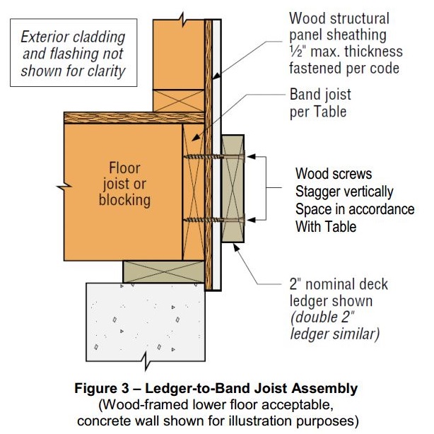
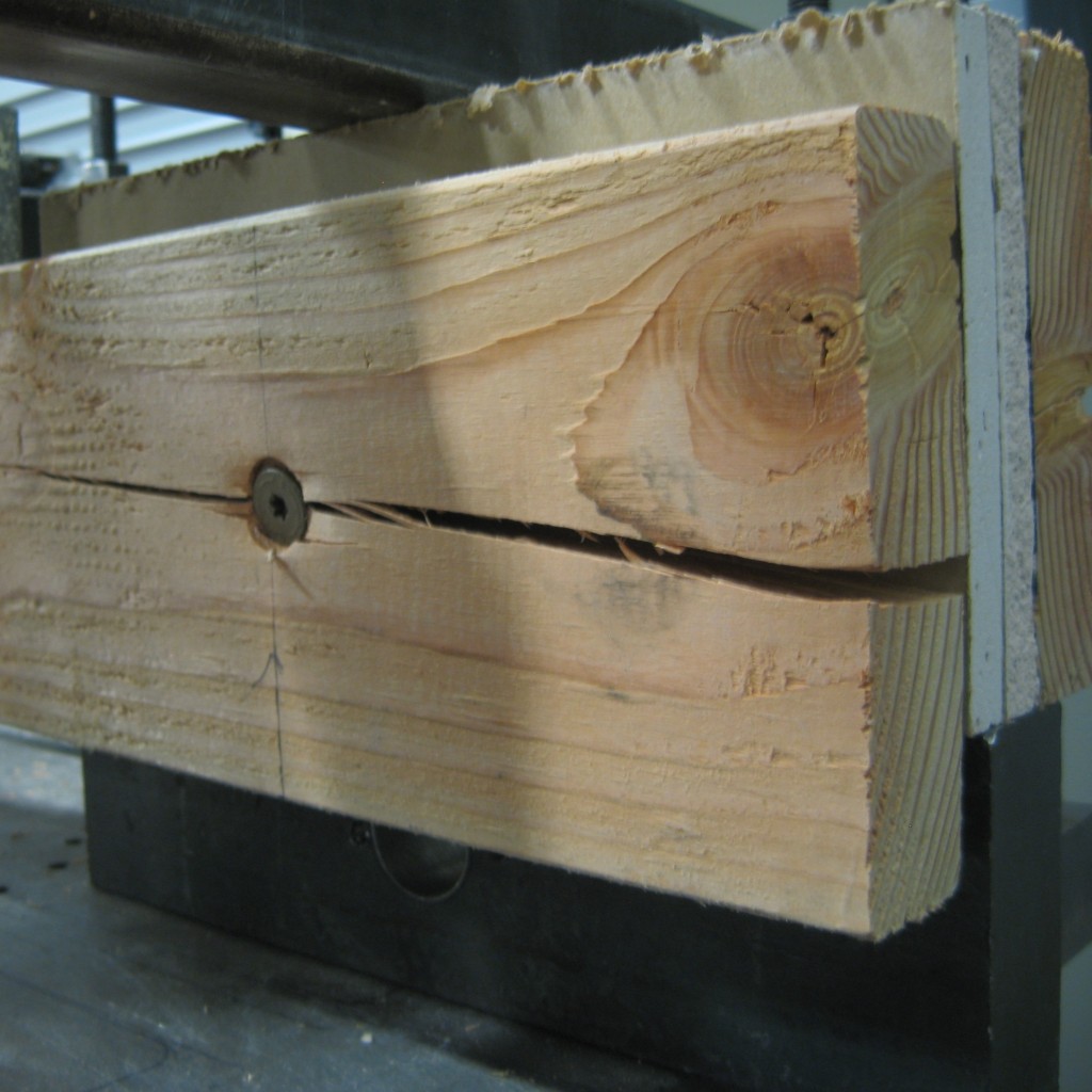
No matter what you call it, gypsum board is found in almost every type of construction. Architects use it for sound and fire ratings, while structural engineers need to account for its weight in our load calculations. A common technical support question we receive is for allowable fastener loads for ledgers to wood framing over gypsum board.

Ledger over Gypboard

One method to evaluate a fastener spanning across gypsum board is to treat the gypsum material as an air gap. Technical Report 12, General Dowel Equations for Calculating Lateral Connection Values, is published by the American Wood Council.

Technical Report 12
Technical Report 12

TR12 has yield limit equations that allow a designer to account for a gap between the main member and side member of a connection. With a gap of zero (g=0), the TR12 equations provide the same results as the NDS yield limit equations.

Technical Report 12 Yield Limit Equations[1]
Technical Report 12 Yield Limit Equations
The equations are fairly complex, but it should be intuitive that the calculated fastener capacity decreases with increasing gap. Engineers are often surprised to see a 40, 50, even 60% drop in fastener capacity with one layer of 5/8” gypsum board. So what else can you do?

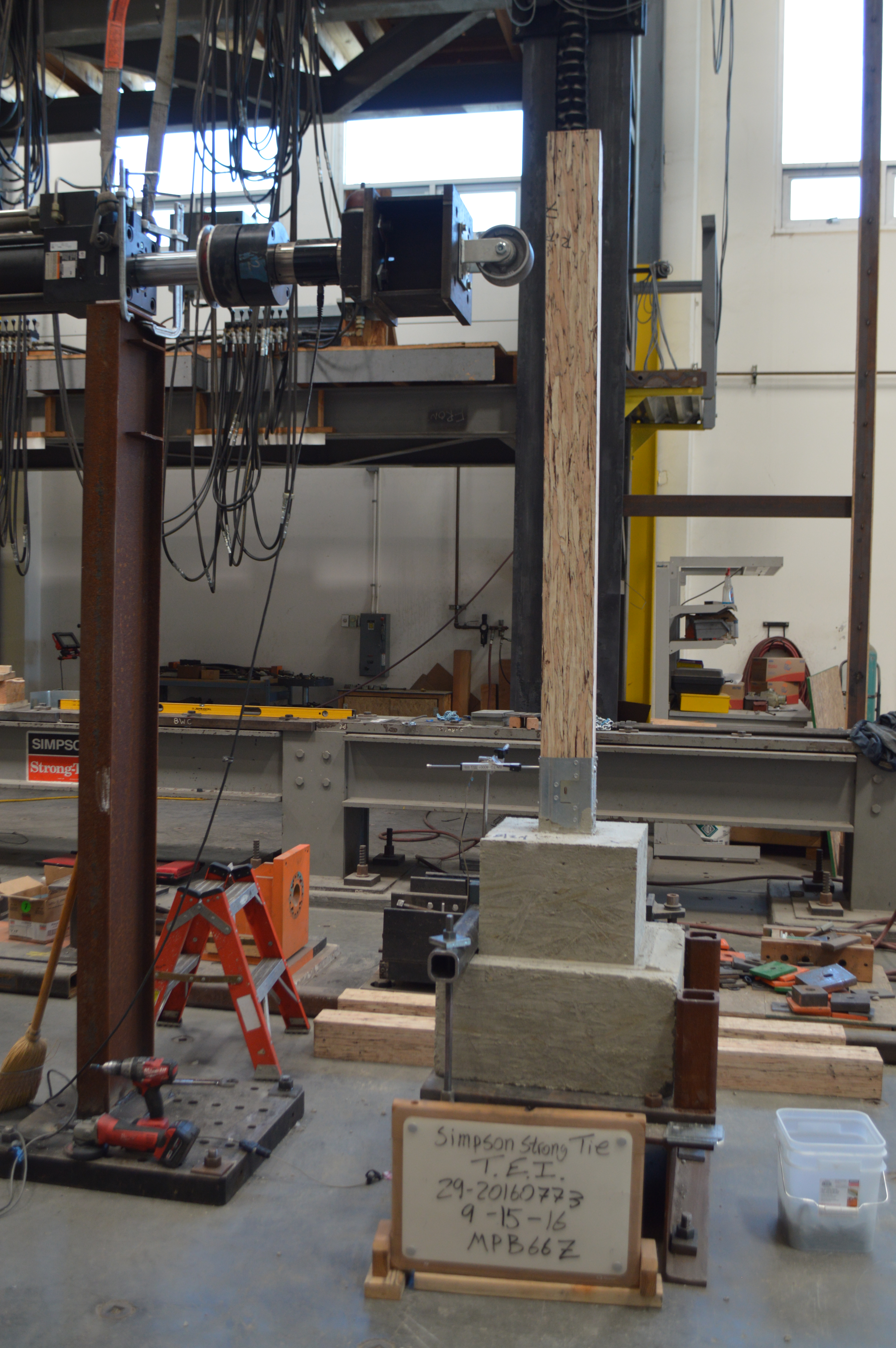
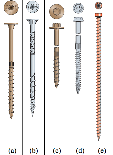
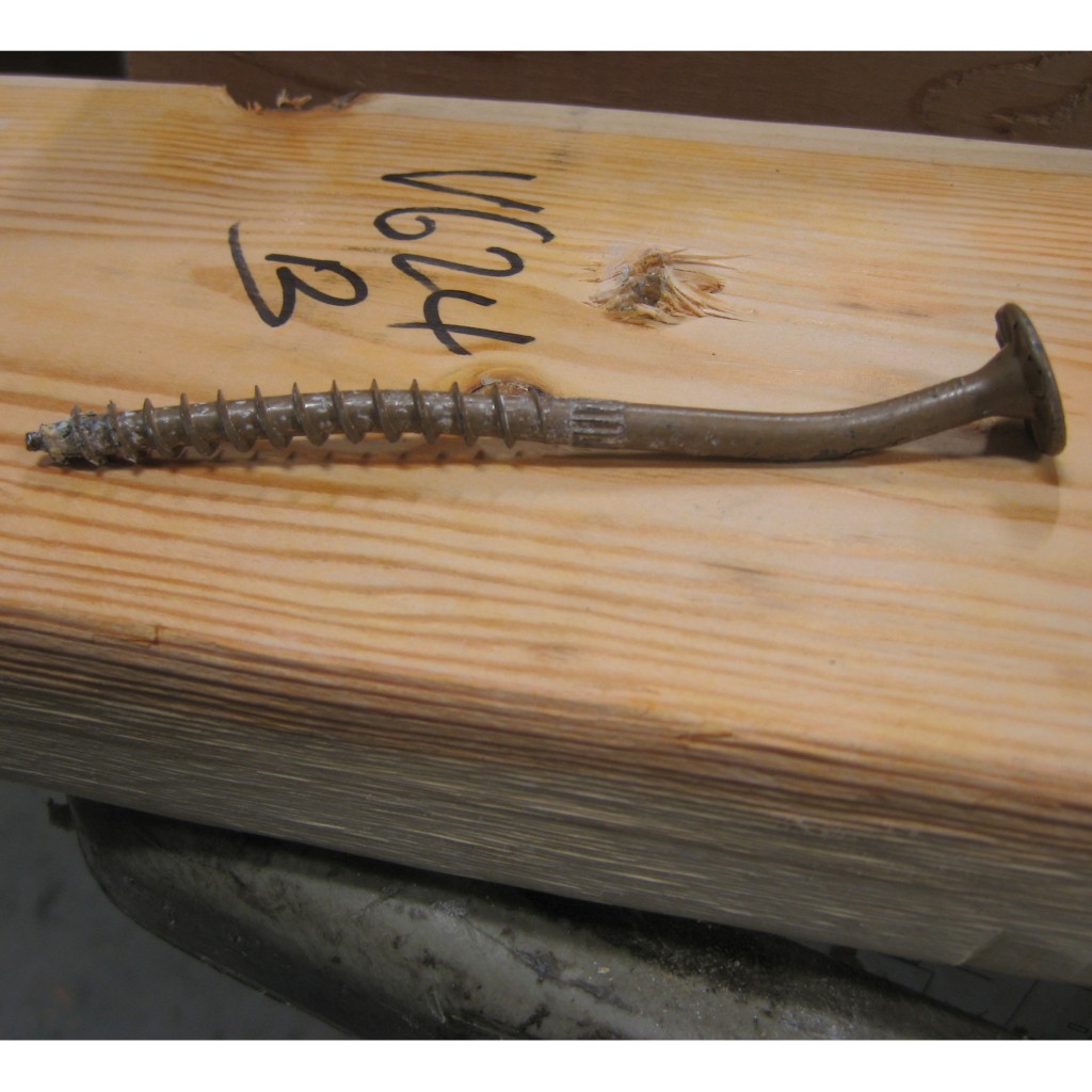
Testing, of course! In So, What’s Behind a Screw’s Allowable Load? I discussed the methods used to load rate a proprietary fastener such as the Simpson Strong-Tie® Strong-Drive® SDS or SDW screws. To recap, ICC-ES Acceptance Criteria for Alternate Dowel Type Fasteners, AC233, allows you to calculate and do verification tests, or load rate based on testing alone. We develop our allowable loads primarily by testing, as the performance enhancing features and material optimizations in our fasteners are not addressed by NDS equations.

So to determine the performance of a fastener installed through gypsum board, we tested the fastener through gypsum board. This is easier to do if you happen to have a test lab with a lot of wood and fasteners in it. We did have to run down to the local hardware store to pick up gypsum board for the testing.

SDWS Over 2 Layer Gypboard
SDWS-Over-2-Layer-Gypboard-Failure
SDWS Over 2 Layer Gypboard Failure

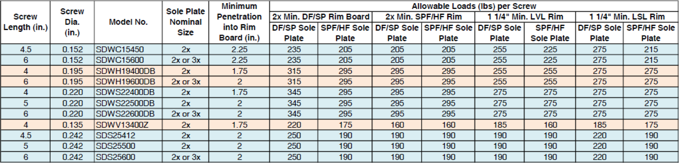
A full set of allowable loads for Strong-Drive SDWH and SDWS are available on strongtie.com. The information is given as single fastener shear values for engineered design, and also screw spacing tables for common ledger configurations. As much fun as writing spreadsheets to do the Technical Report 12 calculations is, having tabulated values based on testing is much easier.

Fastening Systems

In the fastener marketplace, Simpson Strong-Tie stands apart from the rest. Quality and reliability is our top priority.


How Are Deck-Drive™ DWP Screws Load-Rated?

Experiential learning — has it happened to you? Certainly it has, because experiential learning is learning derived from experience. It happens in everyday life, in engineering and in product development, too. For example, experience has taught us that after a product is launched, our customers will find applications for the product that were never expected or listed in the product brief. Also, experience has shown us that larger fasteners tend to be placed in applications that have greater structural and safety demands.

When the larger Deck-Drive™ DWP screws were manufactured, we decided that they should be marketed as “load-rated” screws because they were big enough to support physically large parts and would be expected to provide structural load resistance.

So what is a “load-rated” screw? To Simpson Strong-Tie, a load-rated screw is a threaded fastener that has controlled dimensions and physical properties, as well as validated connection properties.  Load-rated fasteners are also subject to the same quality inspection that would occur if they were undergoing an evaluation report.

Continue Reading

Design More with Our New Steel Deck Diaphragm Calculator App!

People are always innovating new things! There are always new tools, software, apps or, more recently, digital assistants to help us organize our life! Here’s something I want to share with you. Recently my family bought Google Home, and both my boys (ages 8 and 5) are constantly exploring it and testing its capabilities: “Hey, Google, play this music” or “Hey, Google, what time is it?” or “Hey, Google, repeat ‘Nathan is bad.’” While Google Home helps them with the former requests, it simply says, “I am still learning,” in response to commands like “repeat ‘Nathan is bad.’”  It’s funny to see them experiment and come up with creative ideas to use the tool. Many of us appreciate tools that help us be more organized or increase our efficiency or that are simply fun to use. Our new revised diaphragm calculator for designing metal decks is our attempt to help the engineering community get more done in less time.

So What Are the Updates and Revisions?

We have updated our design software to design per Canadian Standards like CSA136 and to design per Limit States Design. The app is so easy to use that you can design a steel deck diaphragm in minutes! The software designs steel decks for both shear and uplift forces acting on the deck and provides tables with diaphragm shear capacities for a given deck span using Simpson Strong-Tie deck fasteners that conform to Canadian codes and standards. These fasteners have an evaluation report, IAPMO UES ER-326, are recognized in SDI (Steel Deck Institute) DDM03 Appendix VII and IX and the CSSBI (Canadian Sheet Steel Building Institute) Design Manual and have FM approvals.

Overview of the App

When you open our diaphragm design software, Steel Deck Diaphragm Calculator, there is an option to “Select your Country.”  You can choose to design for US standards, in which case you select the USA option, or you can select Canada Imperial or Canada Metric, which are new additions. The app has three sections: (1) Optimized Solutions, (2) Diaphragm Capacity Tables and (3) Other Diaphragm Tables. All three options are available for the USA option. The Optimized Solutions help you to design a deck for any given shear and uplift. You can refer to our previous blog, Design Examples for Steel Deck Diaphragm Calculator Web App, for some examples on how to design steel decks using the Optimized Solutions selection. Diaphragm Capacity Tables are available to the USA and both Canada selections. Other Diaphragm Tables is available only to the USA selection.

Metal Deck Diaphragm Design Using Limit States Design (LSD)

When you select Canada for the country, you will have the option to select Diaphragm Capacity Tables as shown in the screen shot below. You can generate diaphragm shear tables by entering:

  1. Steel Deck Information: In this section, you select the type of the deck, the design method, the load type you would like the tables to be generated in and the deck thickness. You can enter uplift if you would like to design the deck for combined shear and tension, or leave the net uplift as zero if you are generating shear-only tables.
  2. Quik Drive Fastener Information: In this section, you input information about the structural and side-lap fasteners.

Click the Calculate button to generate the tables.

A PDF copy of the tables can be generated in either English or French.

This easy-to-use design software can be used by the designers, specifiers or erectors to generate the tables required. More information about our X series of screws (including XL and XM), tools and the required industry approvals for designing the profiled deck diaphragms can be found on our website at strongtie.com.

Please try out the app and let us know your comments and feedback so we can continue to improve our software to better serve your needs!


5 Tips to Stay Informed on Construction News and Industry Updates

For a structural engineer working on multiple projects in various stages of design and construction, it can be challenging to keep up to date on the latest industry trends. However, many of us in the construction industry enjoy learning about new construction techniques and unique projects. Being educated about new technology and design tools can also increase efficiency in the office.Continue Reading

Why You Should Specify Stainless-Steel Screw Anchors When Designing for Corrosive Environments

I was driving under a concrete bridge one nice clear day in Chicago, and I happened to look up to see rusted rebar exposed below a concrete bridge. My beautiful wife, who is not a structural engineer, turned to me and asked, “What happened to that bridge?” I explained that there are many reasons why spalling occurs below a bridge. One common reason is the expansion of steel when it rusts or corrodes.

Continue Reading

3 Hot Tips for Structural Engineers Who Want to Earn Education Credits and Stay Sharp

Do you ever get so busy that you can’t keep up with the structural engineer training opportunities that are available? We have previously shared online resources and webinars that are available to structural engineers, but did you know that you can take advantage of Simpson Strong-Tie regional training centers that offer complimentary workshops and classes about proper specification, product installation and inspection of connectors and structural systems? Here are some tips on staying current with your training.

Simpson Strong-Tie training courses and webinars are focused on improving building standards and the overall safety of structures. With eight training centers across North America, Simpson Strong-Tie provides hundreds of complimentary classes to engineers, architects, builders and code officials each year. In fact, we have trained more than 24,000 participants online and in-person in 2016 alone.

“The workshops are very interactive,” explained Charlie Roesset, Director of Training for Simpson Strong-Tie. “Depending on the course, students may have the opportunity to view product samples or take part in product testing and installations.”

Tip #1 Make Training Offerings Work for You

If you specialize in a specific discipline, look for courses that are targeted to your area of interest or expertise. Simpson Strong-Tie courses include a broad range of topics from anchor system installation and engineered wood frame construction to seismic and high-wind design. We also incorporate the latest building-code updates and industry trends into our training curriculum. No matter where you are in your professional career, we offer a course that’s right for you. There are introductory courses as well as more advanced workshops for repeat and seasoned attendees.

Training participants receive a certificate of attendance with professional development hours (PDHs) at the end of each workshop, and may earn continuing education units (CEUs) and/or learning units (LUs) by completing additional requirements. Simpson Strong-Tie is a registered education provider with a number of industry organizations and associations including CSI, BIA, ACIA, AIBD, ICC, AIA* and IACET**.

Tip #2 Find Trainings That Are Current

Do your research to find workshops and online courses that are regularly updated to reflect changes within the industry. For example, we have regular trainings that focus on the new seismic retrofit ordinances in various municipalities on the West Coast (such as Los Angeles’ Soft-Story Retrofit Ordinance) and others on high-wind design and construction in the Southeast. Our trainings are tailored to your design needs based on your practice’s location.

Full-day workshops typically run from 8:00 a.m. to 4:00 p.m. Classes are often tailored toward specific audiences types to ensure that the training is appropriate and effective. Many courses are team-taught by registered engineers to provide in-depth technical expertise in the subject matter. While much of the instruction is technical in nature, many real-life examples and hands-on demonstrations are provided to help all attendees fully understand the material presented.

Tip #3 Hear What Other Structural Engineers Have to Say

Training

It is always a good sign when others in your field have good things to say about the courses they have taken. Below are some comments past participants have said about our training offerings:

Fred B., S.E., an engineer from Las Vegas, NV, has been a regular attendee of Simpson Strong-Tie workshops. He says the training keeps him informed of topics relevant to his industry and is a great way to keep up with his professional development hours. “Some of the courses offered by other groups are just not that interesting and they can be quite expensive. Simpson programs are interesting, hands-on and free. It’s the whole package.”

Bob N., an engineer from Richmond, VA, wrote, “Keep up the good work; I have found your seminars to be well done, pertinent, and useful. We also specify a lot of your products because of the training and the fact that you have an excellent product line.”

Kathy P., an engineer from Somerville, TX, shares: “You guys are so great! You teach well and keep it interesting. . . . . You support the industry to the benefit of everyone, not just your bottom line, and you make educational credits cost effective. Thank you, thank you, thank you!”

Sign up for a workshop and find out more about Simpson Strong-Tie training programs, including our latest online courses, by visiting www.strongtie.com/workshops.

* Simpson Strong-Tie is registered with the American Institute of Architects, Continuing Education System (AIA CES) as a provider of AIA Learning Units (AIA LUs).

** Simpson Strong-Tie is accredited by the International Association for Continuing Education and Training (IACET) and is authorized to issue the IACET CEU.

Written by Minara El-Rahman in collaboration with the Simpson Strong-Tie Training Department.


Use Strong-Wall® Shearwall Selector to Design Shearwalls

In time for spring and summer 2017 construction projects, Simpson Strong-Tie has launched the newest version of the Strong-Wall Shearwall Selector for use with engineered design. The latest release is an easy-to-use Web-based application (that’s right, no software to download) that has been updated to comply with the 2015 IBC and now provides solutions for all three Strong-Wall Shearwall types: the Steel Strong-Wall® shearwall (SSW), the Strong-Wall wood shearwall (WSW) and the wood Strong-wall shearwall (SW). If you are familiar with the Strong-Wall Shearwall Selector, you can begin using the web application immediately. For those of you who would like to know more about the web app, please read on.Continue Reading

New Moment-Resisting Post Base

Jhakak Vasavada

Jhalak Vasavada is currently a Research & Development Engineer for Simpson Strong-Tie. She has a bachelor’s degree in civil engineering from Maharaja Sayajirao (M.S.) University of Baroda, Gujarat, India, and a master’s degree in structural engineering from Illinois Institute of Technology, Chicago, IL. After graduation, she worked for an environmental consulting firm called TriHydro Corporation and as a structural engineer with Sargent & Lundy, LLC, based in Chicago, IL. She worked on the design of power plant structures such as chimney foundations, boiler building and turbine building steel design and design of flue gas ductwork. She is a registered Professional Engineer in the State of Michigan.

At Simpson Strong-Tie, we strive to make an engineer’s life easier by developing products that help with design efficiency. Our products are designed and tested to the highest standards, and that gives structural engineers the confidence that they’re using the best product for their application.

Installed MPBZ
Figure 1: Installed MPBZ

Having worked in the design industry for almost a decade, I can attest that having a catalog where you can select a product that solves an engineer’s design dilemma can be a huge time- and money-saving tool. Design engineers are always trying to create efficient designs, although cost and schedule are always constraints. Moment connections can be very efficient — provided they are designed and detailed correctly. With that in mind, we developed a moment post base connector that can resist moment in addition to download, uplift and lateral loads. In this post, I would like to talk about moment-resisting/fixed connections for post bases and also talk about the product design process.

Figure 2. MPB44Z Graphic

Lateral forces from wind and seismic loads on a structure are typically resisted by a lateral-force-resisting system. There are three main systems used for ordinary rectangular structures: (a) braced frames, (b) moment frames and (c) shearwalls. Moment frames resist lateral forces through bending in the frame members. Moment frames allow for open frames by eliminating the need for vertical bracing or knee bracing. Moment resistance or fixity at the column base is achieved by providing translational and rotational resistance. The new patent-pending Simpson Strong-Tie® MPBZ moment post base is specifically designed to provide moment resistance for columns and posts. An innovative overlapping sleeve design encapsulates the post, helping to resist rotation at its base.

The allowable loads we publish have what I call “triple backup.” This backup consists of Finite Element Analysis (FEA), code-compliant calculations and test data. Here are descriptions of what I mean by that.

Finite Element Analysis Confirmation

Once a preliminary design for the product is developed, FEA is performed to confirm that the product behaves as we expect it to in different load conditions. Several iterations are run to come up with the most efficient design.

Figure 3. FEA Output of Preliminary MPB Conceptual Design

Code-Compliance Calculations

Load calculations are prepared in accordance with the latest industry standards. The connector limit states are calculated for the wood-post-to-MPBZ connection and for MPBZ anchorage in concrete. Steel tensile strength is determined in accordance with ICC-ES AC398 and AISI S100-07. Wood connection strength is determined in accordance with ICC-ES AC398 and AC13. Fastener design is analyzed as per NDS. SDS screw values are analyzed using known allowable values per code report ESR-2236. The available moment capacity of the post base fastened to the wood member is calculated in accordance with the applicable bearing capacity of the post and lateral design strength of the fasteners per the NDS or ESR values. Concrete anchorage pull-out strength is determined in accordance with AC398.

Test Data Verification

The moment post base is tested for anchorage in both cracked and uncracked concrete in accordance with ICC-ES AC398.

Figure 4. Uplift Test Setup

The moment post base assembly is tested for connection strength in accordance with ICC-ES AC13.

Figure 5: Moment (induced by lateral load application) Test Set Up

The assembly (post and MPBZ) is tested for various loading conditions: download, uplift and lateral load in both orthographic directions and moment. Applicable factor(s) of safety are applied, and the controlling load for each load condition is published in the Simpson Strong-Tie Wood Construction Connectors Catalog.

Now let’s take a look at a sign post base design example to see how the MPBZ data can be used.

Design Example:

Figure 6: Sign Post Base Design Example

The MPB44Z is used to support a 9ʹ-tall 4×4 post with a 2ʹ x 2ʹ sign mounted at the top. The wind load acting on the surface of the sign is determined to be 100 lb. The MPB44Z is installed into concrete that is assumed to be cracked.

  • The design lateral load due to wind at the MPB44Z is 100 lb.
  • The design moment due to wind at the MPB44Z is (100 lb.) x (8 ft.) = 800 ft.-lb.
  • The Allowable Loads for the MPB44Z are:
    • Lateral (F1) = 1,280 lb.
    • Moment (M) = 985 ft.-lb.
  • Simultaneous Load Check:
    • 800/985 + 100/1,280 = 0.89. This is less than 1.0 and is therefore acceptable.

mpbz-deflection-evaultion

We are very excited about our new MPBZ! We hope that this product will get you excited about your next open-structure design. Let us know your thoughts by providing comments here.

Top Three Reasons Why Structural Engineers Should Attend Webinars

We encourage all our employees to always keep learning and seeking out resources that can stimulate new ideas or help improve processes in their jobs. Webinars are a great way for you to stay engaged in your profession and learn new things about the industry. They mix the convenience of online availability with the interactivity of live seminars, and because some are free or offered at a much lower cost than live trainings, they make it even easier to stay up to date on current issues in your field. Our top three reasons why you should attend structural engineering webinars are below:

Close up shot of webinar on a laptop.

Some Webinars Offer Continuing Education Credits

Webinars for structural engineers can be very useful for staying current with professional development requirements. Look to see if the webinar you are interested in attending offers credits. Simpson Strong-Tie offers a wide range of webinars that allow structural engineers to earn CEU and PDH credits. There are plenty of other professional organizations that offer accredited webinars for structural engineers, also. Paul McEntee shares his list of recommended professional resources (including webinars) for structural engineers here.

Learn About Code Changes and Requirements

Staying up to date on code changes and requirements is one of the reasons why continuing education is so important. The Structural Engineers Association of California (SEAOC) has a helpful lunchtime webinar series that delves into 2015 International Building Code (IBC) changes. Simpson Strong-Tie webinars always review current code requirements for the kinds of structural design under discussion. For example, the Best Practices on Prefabricated Wood Shearwall Design webinar covers code reports on shearwall applications.

Learn About the Latest Products and Technology

 If you can’t make it to a live training session, using webinars to learn about the most recent products and technology is an effective way to stay current in the field. Whether you want to learn about the latest in prefabricated Strong-Wall® Shearwall panels or to gain fuller understanding of Best Practices for FRP Strengthening Design, webinars can help you design using the most advanced technology.

What was the best webinar you’ve attended? Why was it so good, or what was it you learned? Let us know in the comments below.

How do you Design Sole-Plate-To-Rim-Board Attachments?

For many years, builders have struggled with the awkward sole-plate-to-rim-board attachment. They often install a few nails and call it good, resulting in a connection with significantly less capacity than needed. This connection is critical to ensure that seismic and wind loads are adequately transferred to the lateral-force-resisting system. With screws becoming much more common in construction, we saw an opportunity to address this problem.

We offer a variety of structural wood screws that have shank diameters ranging from 0.135″ to 0.244″. They form our Strong-Drive® line of structural fasteners. The Simpson Strong-Tie® Strong-Drive SDWC Truss, SDWH Timber-Hex, SDWS Timber, SDWV Sole-to-Rim and SDS Heavy-Duty Connector structural wood screws as shown in Figure 1 can be used to attach sole plates to a rim board as shown in Figure 2. These screws provide structural integrity in the wall-to-floor connection.

The sole-to-rim connection is considered a dry service location. When the sole plate and the rim are both clean wood (not treated), then any of the screws can be used as long as they meet the design loads. However, if one or both members of the connection are treated with fire retardants or preservatives, then you must use the SDWS Timber screw, SDWH Timber-Hex screw or SDS Heavy-Duty Connector screw. The SDWS, SDWH and SDS screws all have corrosion-resistance ratings in their evaluation reports.

Figure 1. Simpson Strong-Tie Strong-Drive screws for fastening the sole-to-rim connection: (a) SDWS Timber screw, (b) SDWV Sole-to-Rim screw, (c) SDWH Timber-Hex screw, (d) SDS Heavy-Duty Connector screw, (e) SDWC Truss screw.
Figure 2. The load rating for the sole-to-rim connection is for transfer of loads parallel to the sole plate to the rim. This is a dry service condition.

The Strong-Drive SDWV structural wood screw has the smallest diameter among these screws. The SDWV is 4″ long and has a 0.135″- diameter shank, and a large 0.400″-diameter ribbed-head with a deep six-lobe recess to provide clean countersinking. It is designed to be fast driving with very low torque. The Strong-Drive SDWS offers one of the larger diameters. It has a 0.220″-diameter shank and is offered in lengths of 4″, 5″ and 6″. It has a large 0.750″-diameter washer head which provides maximum bearing area. Longer screws allow designers to meet the minimum penetration requirement into a rim board, when the sole plate is a 3x or a double 2x member.

We have tested various combinations of sole plates, floor sheathing, and rim boards. Typical test assemblies were built and tested with two (2) Strong-Drive® screws spaced at either 3″ or 6″. Results were analyzed per ICC-ES AC233, “Acceptance Criteria for Alternate Dowel-type Threaded Fasteners.” The allowable loads listed in Table 1 are based on the average ultimate test load of at least 10 tests, divided by a safety factor of 5.0, and are rated per single fastener. The results of these tests can be found in the engineering letter L-F-SOLRMSCRW16.

The evaluated sole plates include southern pine (SP), Douglas fir-larch (DF), hem-fir (HF), and spruce-pine-fir (SPF) in single 2x, 3x or double 2x configurations. Floor sheathing thicknesses are allowed up to 1 1/8″ thick. Rim boards can be LVL or LSL structural composite lumber or DF, SP, HF or SPF sawn lumber. The load rating also assumes that the floor sheathing is fastened separately and per code.

sdwc-load-tables

See strongtie.com for evaluation report information if it is needed.

As a Designer, you can specify any of these Strong-Drive screws that fit your design requirements. Please visit our website and download L-F-SOLRMSCRW16 for more details.

Good luck!