“Structures are connections held together by members” (Hardy Cross)
I heard this quote recently during a presentation at the Midwest Wood Solutions Fair. I had to write it down for future reference because of course, all of us here at Simpson Strong-Tie are pretty passionate about connections. I figured it wouldn’t take too long before I’d find an opportunity to use it. So when I started to write this blog post about the proper selection of a truss-to-wall connection, I knew I had found my opportunity – how fitting this quote is!
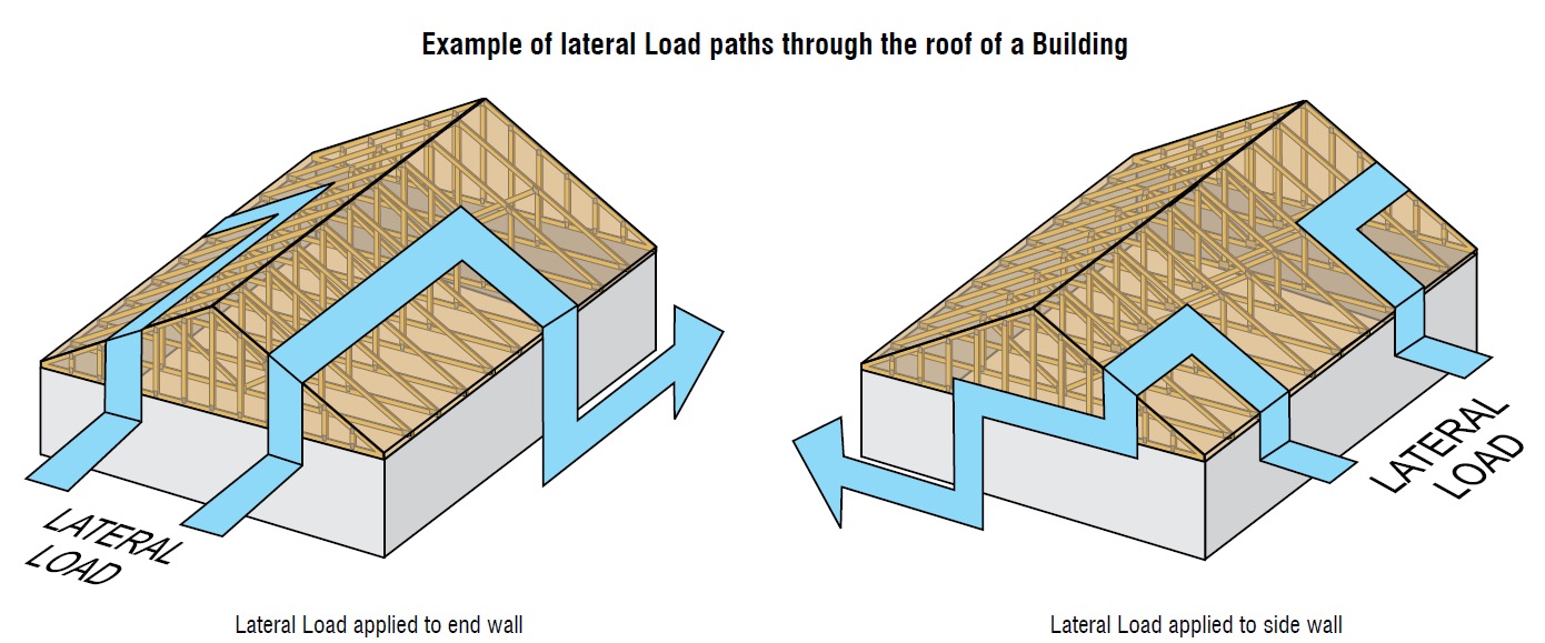
There are plenty of photos of damage wrought by past hurricanes to prove that the connection between the roof and the structure is a critical detail. In a previous blog post, I wrote about whose responsibility it is to specify a truss-to-wall connection (hint: it’s not the truss Designer’s). This blog post is going to focus on the proper specification of a truss-to-wall connection, the methods for evaluating those connections under combined loading and a little background on those methods (i.e., the fun stuff for engineers).
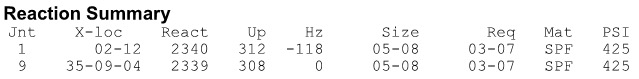
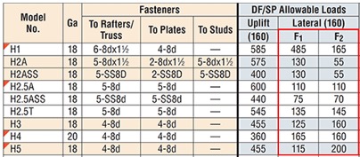
Take a quick look at a truss design drawing, and you will see a reaction summary that specifies the downward reaction, uplift and a horizontal reaction (if applicable) at each bearing location. Some people are tempted to look only at the uplift reaction, go to a catalog or web app, and find the lowest-cost hurricane tie with a capacity that meets or barely exceeds the uplift reaction.
However, if uplift was the only loading that needed to be resisted by a hurricane tie, why would we publish all those F1 and F2 allowable loads in our catalog?
Of course, many of you know that those F1 and F2 allowable loads are used to resist the lateral loads acting on the end and side walls of the building, which are in addition to the uplift forces. Therefore, it is not adequate to select a hurricane tie based on uplift reactions alone.
Excerpt from BCSI (2015 Version)
Where does one get the lateral loads parallel and perpendicular to the plate which must be resisted by the truss-to-wall connection? Definitely not from the truss design drawing! Unless otherwise noted, the horizontal reaction on a truss design should not be confused with a lateral reaction due to the wind acting on the walls – it is simply a horizontal reaction due to the wind load (or a drag load) being applied to the truss profile. It is also important to note that any truss-to-wall connection specified on a truss design drawing was most likely selected based on the uplift reaction alone. There may even be a note that says the connection is for “uplift only” and does not consider lateral loads. In this case, unless additional consideration is made for the lateral loads, the use of that connector alone would be inadequate.
Say, for example, that the uplift and lateral/shear load requirements for a truss-to-wall connection are as follows:
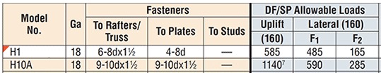
Uplift = 795 lb.
Shear (parallel-to-wall) = 185 lb. (F1)
Lateral (perp-to-wall) = 135 lb. (F2) Based on those demand loads, will an H10A work?
An initial look at the H10A’s allowable loads suggests it might be adequate. However, when these loads are entered into the Connector-Selector, no H10A solution is found.
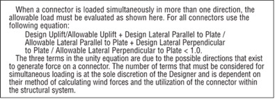
Combined Uplift, F1 and F2 Loads
Why? Because Connector-Selector is evaluating the connector for simultaneous loading in more than one direction using a traditional linear interaction equation approach as specified in our catalog:
If the shear and lateral forces were to be resisted by another means, such that the H10A only had to resist the 795 lb. of uplift, then it would be an adequate connector for the job. For example, the F1 load might be resisted with blocking and RBC clips, and the F2 loads might be resisted with toe-nails that are used to attach the truss to the wall prior to the installation of the H10A connectors. However, if all three loads need to be resisted by the same connector, then the H10A is not adequate according to the linear interaction equation.
Uplift Only
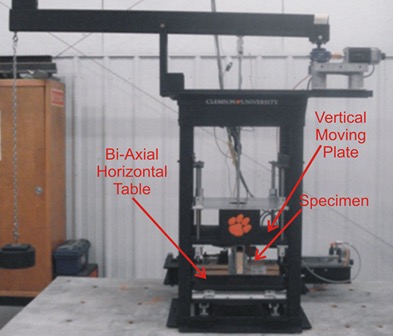
Some might question how valid this method of evaluation is – Is it necessary? Is it adequate? How do we know? And that is where the interesting information comes in. Several years ago, Simpson Strong-Tie partnered with Clemson University on an experimental study with the following primary objectives:
1. To verify the perceived notion that the capacity of the connector is reduced when loaded in more than one direction and that the linear interaction equation is conservative in acknowledging this combined load effect.
2. To propose an alternative, more efficient method if possible.
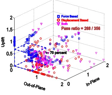
Three types of metal connectors were selected for this study – the H2.5A, H10, and the META20 strap – based on their different characteristics and ability to represent general classes of connectors. The connectors were subjected to uni-axial, bi-axial and tri-axial loads and the normalized capacities of the connectors were plotted along with different interaction/design surfaces.
These interaction plots were used to visualize and parameterize the combined load effect on the capacity of the connectors. The three different interaction plots that were examined were the traditional linear relationship, a quadratic interaction surface and a cuboid design space.
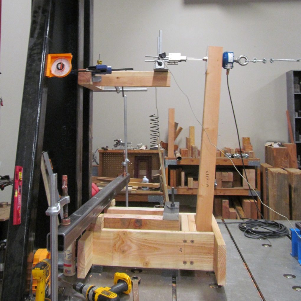
Tri-axial Test FrameInteraction plot for tri-axial loads on a cuboid design space
The results? Not only was the use of the linear interaction equation justified by this study, but a new, more efficient cuboid design surface was also identified. It provides twice the usable design space of the surface currently used for tri-axial loading and still provides for a safe design (and for the bi-axial case, it is even more conservative than the linear equation). This alternative method is given in our catalog as follows:
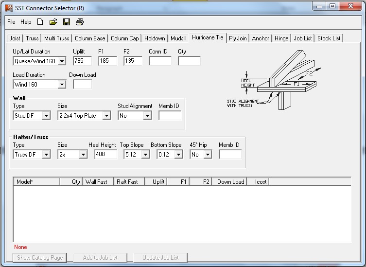
Now we can go back to the H10A and re-evaluate it using this alternative method:
As it turns out, the H10A does have adequate capacity to resist the simultaneous uplift, shear and lateral loads in this example. This just goes to show that the alternative method is definitely worth utilizing, whenever possible, especially when a connector fails the linear equation.
For more information about the study, see Evaluation of Three Typical Roof Framing-to-Top Plate/Concrete Simpson Strong-Tie Metal Connectors under Combined Loading.
What is your preferred method for resisting the combined shear, lateral and uplift forces acting on the truss-to-wall connections? Let us know in the comments below!
This week we’re blogging about corrosion, and we’re not talking about rusting of the soul — we’re talking about oxidation of steel.
In 2014, we reviewed our corrosion protection recommendations for new catalog publications. In doing so, we realized that we could facilitate selection of hardware and fasteners if our Corrosion Resistance Classifications for treated wood were linked to common design conditions described in the codes. We made some revisions to our Corrosion Resistance Classifications during that exercise. This blog post talks about those changes and some current related activity in the wood treatment industry.
The common design conditions for corrosion-resistant wood construction include the wood materials with associated treatments and the environmental corrosion agents. The American Wood Protection Association (AWPA), which is an ANSI-accredited consensus standards organization, publishes the code-referenced standard, AWPA U1-15 Use Category System: User Specifications for Treated Wood.
When you specify treated wood, this is the standard that defines the appropriate treatment chemicals and chemical retentions depending on the exposure condition and bio-hazard, which the AWPA has summarized into a Use Category (UC) system. Figure 1 is a clip from the AWPA web site that gives a glimpse at the UC system. As the UC rating increases from UC1 to UC5, the chemical retention increases because the bio-hazard is increasing. Corrosion hazards are directly related to the combination of treatment chemical, treatment chemical retention and use environment.
The AWPA UC system does not include environmental corrosion agents. As a result, we had to separately integrate those with treatment chemical effects as we developed the corrosion resistance classifications.
Finally, one more evaluation system had to be addressed: the exposure conditions of ICC-ES AC257 — Corrosion Resistant Fasteners and Evaluation of Corrosion Effects of Wood Treatment Chemicals. In the end, we developed Corrosion Resistance Classifications that considered the AWPA Use Categories, environmental corrosion agents and the ICC-ES AC257 exposure conditions.
Some of you may be thinking that we have not mentioned another aspect of corrosion — galvanic corrosion. Galvanic corrosion results when metals with dissimilar electrical potentials are placed in contact in the presence of an electrolyte (water). We’ll take up galvanic corrosion in a subsequent blog post.
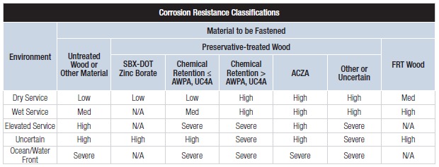
Our basic Corrosion Resistance Classification table is shown in Figure 2.
Figure 2. Corrosion Resistance Classifications (from C-F-2014, p. 15, or strongtie.com)
The ratings shown in the table — Low, Medium, High and Severe — refer to the corrosion resistance of Simpson Strong-Tie coating systems and base metals. An example of a coating system that is rated “Low” is paint or electro-galvanized zinc. An example of a material rated for “Severe” corrosion conditions is Type 316 stainless steel.
To use the Corrosion Resistance Classifications table, find the Environment, then move to the correct column in the Material to Be Fastened section; identify a rating. Then look in the companion table labeled “Corrosion Resistance Recommendations” to identify a coating or base metal that is appropriate for your project. Be sure to read the table notes to the Corrosion Resistance Classifications for exceptions and limitations. We implemented this system to simplify product selection. Let’s take a look at each aspect that contributes to the Corrosion Resistance Classifications table.
Environment
The environment captures the moisture, atmospheric conditions and other elements that affect corrosion rate. “Dry Service” usually means an interior space with low moisture content or dampness. No liquid water is present in this sort of environment. The absence of moisture limits the electrochemical reaction needed to produce what we see as corrosion. “Wet Service” usually means exterior exposure and involves liquid water as direct exposure or condensation and wood moisture contents that can exceed air-dry conditions and may be temporary or persist for prolonged periods. We incorporated environmental agents with the “Elevated Service and Ocean/Waterfront” conditions. These environmental agents include fumes, acid rain, airborne salinity, etc. The “Uncertain Environment” was included for the Designer who does not know the corrosive conditions in service.
Material Being Fastened
Here we distinguish between clean materials and wood treated with chemicals — wood preservatives or fire-retardant chemicals (FRT). Untreated softwoods used for framing are generally not significantly corrosive. This does not include cedars and redwood, which are a special case. Cedars tend to be corrosive and particularly prone to staining when fastened with carbon steel hardware and fasteners. As a result, our recommendations for untreated softwoods are generally a function of the environment — moisture, weather exposure and corrosion agents such as salt spray, sulfur or fertilizer fumes and acid rain are all examples.
Some treatment chemicals do not significantly increase the corrosion hazard. These are the SBX-DOT treatment chemicals (inorganic boron and borate treatments). These are not typically used in exterior environments or for high-moisture conditions. The preservatives are not chemically bound to the wood and they can leach out under exposure to liquid moisture, which would leave the wood unprotected. The corrosion hazard attendant to these chemicals is similar to that of untreated wood and the codes permit the use of bare carbon steel in contact with wood treated with these chemicals (IBC2015, Section 2304.10.5.1 and IRC2015, Section R317.3.1 (exception 3)).
Most of the waterborne chemicals in common use contribute to an elevated corrosion hazard. Some of the common wood treatment chemicals include formulations of alkaline copper quaternary (ACQ), copper azole (CA), ammoniacal copper zinc arsenate (ACZA) and micronized copper azole (MCA). The AWPA UC system defines the exposure conditions for each Use Category as well as the chemical retention required to prevent a decay failure. The MCA formulations are alternatives to those specified in the code-referenced standard through the evaluation report process and are not standardized by the AWPA. The evaluation report process for wood preservatives requires the submission of evidence in compliance with ICC-ES AC326 — Proprietary Wood Preservative Systems — Common Requirements for Treatment Process, Test Methods and Performance.
We realize that UC4A is a general-use ground-contact condition, and further, it is the maximum necessary specification for treated wood in many building applications. The Simpson Strong-Tie Corrosion Resistance Classifications recognize that the corrosion hazard of treatment chemical retentions for UC4A in Wet Service is a “Medium” corrosion condition (with the exception of ACZA, which is rated “High” in Wet Service). This means that carbon steel products with sufficient corrosion resistance (e.g., ZMAX, double barrier coating, etc.) can be used in these conditions assuming no other corrosion-causing agents are present.
On the other hand, the moisture conditions and treatment chemical retentions are elevated in UC4B and UC4C, and there is also a potential for salt exposure, which further escalates the corrosion hazard. In these conditions, stainless steel is generally recommended for connectors and fasteners as the best material for mitigating the corrosion risk.
The last column in the Corrosion Resistance Classifications table is devoted to FRT wood. Fire-retardant treatment chemicals are proprietary and are deemed to meet the requirements of the codes through the evaluation report process (ICC-ES AC66 — Acceptance Criteria for Fire-Retardant-Treated Wood). We cannot evaluate the corrosion resistance of hardware to all of the FRT formulations. However, we have reviewed most of the FRT evaluation reports for corrosion information. The corrosion effects of FRT chemicals, like preservative treatment chemicals, are minimized in dry-service conditions because the electrochemical reaction cannot progress or is slowed without an electrolyte. The Corrosion Resistance Classifications reflect that information. The Designer should always follow the FRT evaluation reports in addition to considering our recommendations.
It is important to note that the Corrosion Resistance Classifications are not associated with specific applications. Rather, the ratings are based on the integrated effects of the environment and the wood treatment where the chemical retentions given in the AWPA Use Category system play an important role in the ratings. This makes it relatively straightforward to select hardware that is adequate for a design environment.
Changes to the AWPA U1 Standard and Effects on Corrosion Resistance Classifications
As noted here and in the online JLC article, wood preservative chemicals can achieve compliance with the codes by either of two methods:
The product is a generic product (e.g., ACQ-D or CA-B) and is listed in the AWPA U1 standard; or
The product has an evaluation report obtained by submitting evidence in accordance with ICC-ES AC326 — Proprietary Wood Preservative Systems — Common Requirements for Treatment Process, Test Methods and Performance.
You may be aware that the AWPA is revising its code-referenced standard, AWPA U1-15, Use Category System: User Specification for Treated Wood. The consensus process is ongoing and is not complete. However, AWPA member chemical companies (Viance, Koppers, and Arch) have placed information in the market. In parallel with the AWPA, ICC-ES has modified AC326 to reflect the changes ongoing in the AWPA U1 standard. Simpson Strong-Tie has been in contact with the AWPA, other industry associations and industry professionals to understand the potential effects on metal hardware of the AWPA U1 and ICC-ES AC326 revisions.
The proposed revisions to the AWPA U1 standard modify the definitions for UC3A, UC3B, UC4A, UC4B and UC4C. The most important revisions are to UC3B and UC4A. The new definition for applications in UC3B suggests that beams and joists in decks and docks may have bio-hazards that exceed the UC3B assumptions, while the new UC4A definition will include above-ground applications with ground- contact hazards. The revised AWPA U1 standard will be published in the May–June 2016 time frame; AWPA U1-16 will be included in the 2018 codes.
The revision to ICC-ES AC326 also modifies the definitions for UC3B, UC4A and UC4B. ICC-ES AC326 has an implementation date of July 2016, which will cause some changes to specifications this summer. Micronized copper azole (MCA) formulations are the most common treatment chemicals that will be affected by this action.
Revisions to the Use Category definitions are being driven by two issues:
Wood treated for UC3 is sometimes used in near-ground applications where the bio-hazard is more like UC4.
Under-treatment compromises the margin of safety to bio-hazards, which can lead to decay failures.
Rather than revisit the retention specifications in AWPA U1 standard, the AWPA is modifying the definitions for the Use Categories that are involved, and that language has been carried into ICC-ES AC326 to ensure that the two systems are consistent with each other. The result of changes to the Use Category definitions will likely cause some specifications to change from UC3B to UC4A or from UC4A to UC4B. The main effects will likely be to specifications in eastern and southern states, where there may be more chemical in the wood to meet retention specifications.
The Simpson Strong-Tie Corrosion Resistance Classifications make specific reference to the corrosive levels of environmental conditions and the chemical treatment and retentions of the AWPA Use Categories, not to applications. As a result, the AWPA U1 revisions and the parallel changes to ICC-ES AC326 will not necessitate a change in our corrosion recommendations, because the chemical retentions for each Use Category have not changed. However, your hardware specifications could change for typical applications depending on the Use Category of the treated wood in your project. Our information suggests that this issue is still not settled within the industry, and we will pass along information as we learn it.
Simpson Strong-Tie is currently preparing new catalogs for the coming year and will be updating the corrosion information in those publications and our website. We’re interested in your experience with our Corrosion Resistance Classifications and whether you have suggestions for how we might make the content more useful to you.
We know many of you visit our website on a regular basis for product and technical information and to use our software, calculator tools and other web apps. If you haven’t visited strongtie.com recently, it has a new look and several new features, including enhanced search and browsing and a mobile-friendly design. Here are some of the new features and site improvements:
Update-to-date product information: If there is a new code report, catalog or product you will be able to find that information on our new website first. It has the latest product and technical information while retaining the same features and information you expect.
Enhanced search and browsing: You can now search for our products based on specific product attributes. Our enhanced search capabilities allow you to explore our collection of products by applying filters so you can quickly and easily browse and find the products that you are looking for.
Mobile-friendly: Our new site has a responsive design that allows you to view the site in any format. From large desktops to mobile devices, you can view our site in the office or while on the go.
Enhanced Visuals: We have added new and improved photographs, illustrations and graphics so that you can see our products in greater detail.
We hope the new website better serves your design and technical needs. If you have any suggestions, comments or feedback, please email us at web@strongtie.com or leave a comment below.
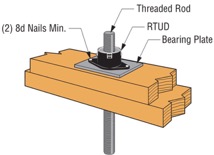
Over the weekend, I had the pleasure of watching my daughter in her cheer competition. I was amazed at all the intricate detail they had to remember and practice. The entire team had to move in sync to create a routine filed with jumps, tumbles, flyers and kicks. This attention to detail reminded me of the new ratcheting take-up device (RTUD) that Simpson Strong-Tie has just developed to accommodate 5/8″ and ¾” diameter rods. The synchronized movement of the internal inserts allows the rod to move smoothly through the device as it ratchets. The new RTUDs are cost effective and allow unlimited movement to mitigate wood shrinkage in a multi-story wood- framed building. When designing such a building, the Designer needs to consider the effect of shrinkage and how to properly mitigate it.
Shrinkage is natural in a wood member. As moisture reaches its equilibrium in a built environment, the volume of a wood member decreases. The decrease in moisture causes a wood-framed building to shrink.
The IBC allows construction of light-framed buildings up to 5 and 6 stories in the United States and Canada respectively. Based on the type of floor framing system, the incremental shrinkage can be up to ¼” or more per floor. In a 5-story building, that can add up to 1-¼” or more and possibly double that when construction settlement is included.
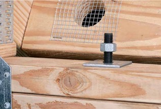
Typical Example of gap forming between nut and plate when wood shrinkage at top level occurs without shrinkage device.
The Simpson Strong-Tie Wood Shrinkage Calculator is a perfect tool to determine the total shrinkage your building can experience.
Wood Shrinkage Calculator
In order to accommodate the shrinkage that occurs in a multi-story wood-framed building, Simpson Strong-Tie offers several shrinkage compensating devices. These devices have been tested per ICC-ES Acceptance Criteria 316 (AC316) and are listed under ICC-ES ESR-2320 (currently being updated for the new RTUD5, RTUD6, and ATUD9-3).
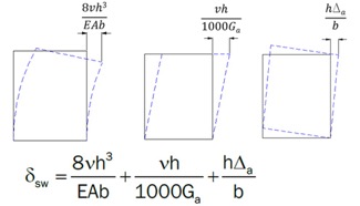
AC316 limits the rod elongation and device displacement to 0.2 inches between restraints in shearwalls. This deflection limit is to be used in calculating the total lateral drift of a light-framed wood shearwall.
3 Part Shearwall Drift Equation
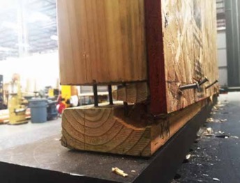
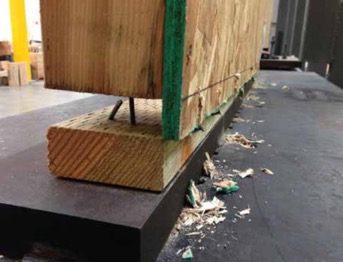
The 0.2-inch allowable limit prescribed in AC316 is important to a shearwall’s structural ability to transfer the necessary lateral loads through the structure below to the foundation level. This limit assures that the structural integrity of the nails and sill plates used to transfer the lateral loads through the shearwalls is not compromised during a seismic or wind event. Testing has shown that sill plates can crack when excessive deformation is observed in a shearwalls. Nails have also been observed to pull out during testing. Additional information on this can be found here.
Sill Plates Cracked due to excessive uplift at ends of shearwall.Nails pull out due to excessive uplift at ends of shearwall.
In AC316, 3 types of devices are listed.
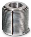
Compression-Controlled Shrinkage Compensating Device (CCSCD): This type of device is controlled by compression loading, where the rod passes uninterrupted through the device. Simpson Strong-Tie has several screw-type take-up devices, such as the Aluminum Take-Up Device (ATUD) and the Steel Take-Up Device (TUD), of this type.
ATUD (CCSCD)
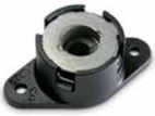
Tension-Controlled Shrinkage Compensating Device (TCSCD): This type of device is controlled by tension loading, where the rod is attached or engaged by the device and allows the rod to ratchet through as the wood shrinks. The Simpson Strong-Tie Ratcheting Take-Up Device (RTUD) is of this type.
RTUD (TCSCD)
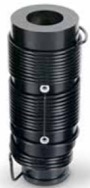
Tension-controlled Shrinkage Compensating Coupling Device (TCSCCD): This type of device is controlled by tension loading that connects rods or anchors together. The Simpson Strong-Tie Coupling Take-Up Device (CTUD) is of this type.
CTUD (TCSCCD)
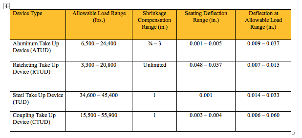
Each device type has unique features that are important in achieving the best performance for different conditions and loads. The following table is a summary of each device.
The most cost-effective Simpson Strong-Tie shrinkage compensation device is the RTUD. This device has the smallest number of components and allows the rod unlimited travel through the device. It is ideal at the top level of a rod system run or where small rod diameters are used. Simpson Strong-Tie RTUDs can now accommodate 5/8″ (RTUD5) and ¾” (RTUD6) diameter rods.
How do you choose the best device for your projects? A Designer will have to consider the following during their design.
RTUD Assembly
Rod Tension (Overturning) Check:
Rods at each level designed to meet the cumulative overturning tension force per level
Standard and high-strength steel rods designed not to exceed tensile capacity as defined in AISC specification
Standard threaded rod based on 36 / 58 ksi (Fy/Fu)
High-strength Strong-Rod based on 92 / 120 ksi (Fy/Fu
H150 Strong-Rod based on 130 / 150 ksi (Fy/Fu)
Rod elongation (see below)
Bearing Plate Check
Bearing plates designed to transfer incremental overturning force per level into the rod
Bearing stress on wood member limited in accordance with the NDS to provide proper bearing capacity and limit wood crushing
Bearing plate thickness has been sized to limit plate bending in order to provide full bearing on wood member
Shrinkage Take-Up Device Check
Shrinkage take-up device is selected to accommodate estimated wood shrinkage to eliminate gaps in the system load path
Load capacity of the take-up device compared with incremental overturning force to ensure that load is transferred into rod
Shrinkage compensation device deflection is included in system displacement
Movement/Deflection Check
System deformation is an integral design component impacting the selection of rods, bearing plates and shrinkage take-up devices
Rod elongation plus take-up device displacement is limited to a maximum of 0.2″ per level or as further limited by the requirements of the engineer or jurisdiction
Total system deformation reported for use in Δa term (total vertical elongation of wall anchorage system per NDS equation) when calculating shearwall deflection
Both seating increment (ΔR) and deflection at allowable load (ΔA) are included in the overall system movement. These are listed in the evaluation report ICC-ES ESR-2320 for take-up devices
Optional Compression Post Design
Compression post design can be performed upon request along with the Strong-Rod System
Compression post design limited to buckling or bearing perpendicular to grain on wood plate
Anchorage design tools are available
Anchorage design information conforms to AC 318 anchorage provisions and Simpson Strong-Tie testing
In order to properly design a continuous rod tie-down system for your shearwall overturning restraint, all of the factors listed above will need to be taken into consideration.
A Designer can also contact Simpson Strong-Tie by going to www.strongtie.com/srs and filling out the online “Contact Us” page to have Simpson Strong-Tie design the continuous rod tie-down system for you. This design service does not cost you a dime. A few items will be required from the Designer in order for Simpson Strong-Tie to create a cost-effective rod run (it is recommended that on the Designer specify these in the construction documents):
There is a maximum system displacement of 0.2″ per level, which includes rod elongation and shrinkage compensation device deflection. Some jurisdictions may impose a smaller deflection limit.
Bearing plates and shrinkage compensation devices are required at every level.
Cumulative and incremental forces must be listed at each level in Allowable Stress Design (ASD) force levels.
Construction documents must include drawings and calculations proving that design requirements have been met. These drawings and calculations should be submitted to the Designer for review and the Authority Having Jurisdiction for approval.
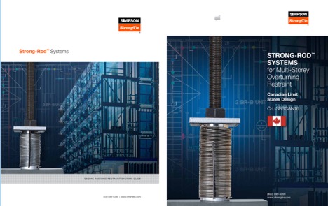
More information can be obtained from our website at www.strongtie.com/srs, where a new design guide for the U.S., F-L-SRS15, and a new catalog for Canada, C-L-SRSCAN16, are available for download.
US Design Guide F-L-SRS15 and Canadian Catalog C-L-SRSCAN16
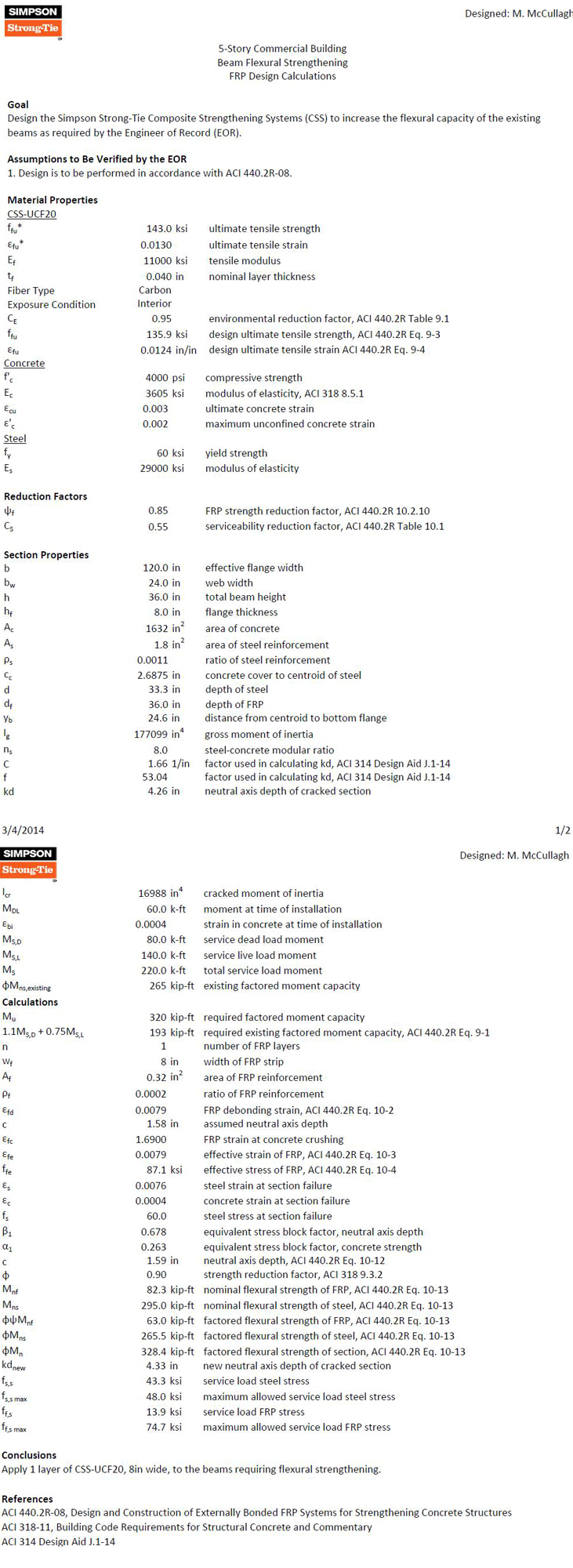
The following FRP Design example walks the reader through the typical process for designing an FRP strengthening solution for a concrete T-beam per ACI 440.2R Guide for the Design and Construction of Externally Bonded FRP Systems for Strengthening Concrete Structures.
One of the most important initial checks for an Engineer of Record is to confirm that the unstrengthened structure can support the load combination shown in Equation 5.5.1 in ACI 562 Code Requirements for Evaluation, Repair, and Rehabilitation of Concrete Buildings:
Eq. 5.5.1: (φRn)existing ≥ (1.2SDL + 0.5SLL)new
This check is to prevent a structural failure in case that the strengthening is damaged in an extraordinary event. If the structural element cannot pass this check, then external reinforcement is not recommended.
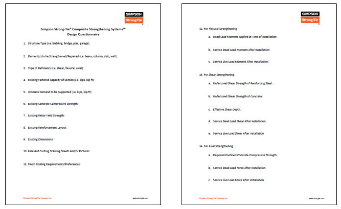
We have a Design Questionnaire where we ask Engineers of Record for more specific information related to the element to be strengthened:
For this particular example, the following information was provided for the concrete T-beam.
1. Structure Type (e.g., building, bridge, pier, garage):
5-story commercial concrete building
2. Element(s) to be Strengthened/Repaired (e.g., beam, column, slab, wall):
Reinforced concrete beams
3. Type of Deficiency (e.g., shear, flexural, axial):
Flexural
4. Existing Factored Capacity of Section (e.g., kips, kip-ft):
265 kip-ft
5. Ultimate Demand to be Supported (e.g., kips, kip-ft):
320 kip-ft
6. Existing Concrete Compressive Strength:
4,000 psi
7. Existing Rebar Yield Strength:
60 ksi
8. Existing Reinforcement Layout:
3 #7s 2.6875 inches from bottom of web to centroid of steel
9. Existing Dimensions:
36 inches total beam height, 8 inches slab, 24 inches web width, 120 inches effective slab width
We then plug this information into our design program to come up with an FRP solution that meets the needs of the member:
For a beam that was at 83% of the capacity required for the new loading, we specified a simple, low-impact FRP solution to maintain clearances under the beams. If a traditional fix of adding cross-section to the beam had been specified instead, then additional concrete and rebar would need to be added to the beam, which would impact clearances under the beam and also increase the seismic weight of the building. The additional weight could also translate all the way through the building and even impact footing designs.
FRP can be used to increase the flexural strength up to 40% per ACI 440.
For your next retrofit project, please contact Simpson Strong-Tie to see if FRP would be an economical choice for strengthening your concrete or masonry element.
Add Simpson Strong-Tie to Your Design Team
Simpson Strong-Tie Composite Strengthening Systems™ is unlike choosing any other product we offer.
For your next retrofit project, please contact Simpson Strong-Tie to see if FRP would be an economical choice for strengthening your concrete or masonry element.
A previous blog post described how Simpson Strong-Tie tests and loadrates connectors used with cold-formed steel structural members per acceptance criteria ICC-ES AC261.
This week, I would like to describe how we test and determine engineering design values for RCKW, Rigid Connector Kneewall, in a CFS wall assembly and how the data can help designers perform engineering calculations accurately and efficiently.Continue Reading
As many of you know, LinkedIn is a social networking website specifically aimed at business professionals and is designed to help you connect and network with people you know and trust. You can add colleagues, peers and others as contacts and send them messages. You can create and update your personal profile to let your contacts know about your professional activities, and both recommend or endorse your contacts and get recommended or endorsed by your contacts for your professional skills. In addition, you can join groups to communicate with other professionals within the same sector or industry. You are also able to ask and answer industry-related questions, and to learn about and apply for job openings.
A basic membership on LinkedIn is free, but you can also upgrade your account in order to have access to professionals outside of your network.
To help guide you, here are some best practices for how to set up and optimize your LinkedIn account.
Update and Complete Your Profile
Having a complete and updated profile on LinkedIn allows you to put your best face forward. Make sure to summarize your role and responsibilities and current and past work experience, highlighting the details you think will make a prospective customer want to work with you. Include a professional-looking headshot and your current contact information. LinkedIn will even tell you your profile strength on the right-hand rail.
Join Industry Specific Groups
Joining groups that are relevant to our industry will allow you to participate in online industry discussions. Answering questions related to your field of expertise within these discussions is an excellent way to position yourself as an authority and build your professional reputation. Here are some structural engineering groups that you can start with:
Connect with people you already know using your email contacts. This will help you maintain your existing relationships as well as branch out to connect with industry-related people your contacts may know. Another great feature of LinkedIn is that it will tell you “People You May Know” based on where you work or are already linked to. This feature will help you find meaningful connections.
Follow the Company Page and Share Posts
Simpson Strong-Tie has a company LinkedIn page to connect with customers. Company pages are a way to keep up to date on trends in design and building materials, code changes, product launches and other industry news. Make sure to follow the Simpson Strong-Tie company page so that you can stay informed about our latest news and updates.
Manage Privacy Settings
Make sure to review and manage your privacy settings to help you control how many people can view your activities and personal information. You can do this by hovering your mouse on your thumbnail image on the far right- hand side of your home page.You should see an Account & Settings drop-down menu appear with an option that says “Privacy & Settings: Manage.” Click this option. Once you are there, you can manage all of your privacy settings.
How do you use LinkedIn as part of your engineering career? Let us know in the comments below.
This week’s post comes from Brad Erickson, who is the Engineering Manager for the Composite Strengthening Systems™ product line at our home office. Brad is a licensed civil and structural engineer in the State of California and has worked in the engineering field for more than 17 years. After graduating from Cal Poly, San Luis Obispo with a B.S. in Architectural Engineering, he worked for Watry Design, Inc. as an Associate Principal before coming to Simpson Strong-Tie. Brad is the Engineering Manager for Composite Strengthening Systems and his experience includes FRP design, masonry and both post-tensioned and conventional concrete design. While not at work, Brad enjoys spending time carting his three kids around to their competitive soccer games and practices.
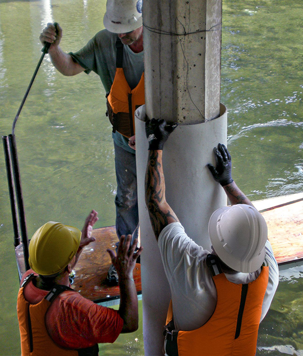
Have you ever had a concrete or masonry design project where rebar was left out of a pour? Chances are, the answer is yes. Did you wish you could solve this problem by putting rebar on the outside of that element? That’s exactly what Simpson Strong-Tie Composite Strengthening Systems™ (CSS) can do for you and your project. In effect, composites act like external rebar for your concrete or masonry element. Composites can be used in similar configurations to rebar but are applied on the exterior surface of the element being strengthened.
The initial offering in our CSS line is our fiber-reinforced polymer (FRP) product group. An FRP composite is created by taking carbon or glass fabric and saturating it with a two-part epoxy which, when cured, creates the composite. Together, the weight of the fabric and the number of layers in the composite determine how much strength it will add to your concrete or masonry element.
Another form of FRP composite is a precured carbon laminate. The carbon fibers are saturated in the manufacturing facility and are attached to the structure using CSS-EP epoxy paste and filler, an epoxy with a peanut butter–like consistency. We also carry paste profilers (pictured below) that help contractors apply the proper amount of paste to a piece of precured laminate.
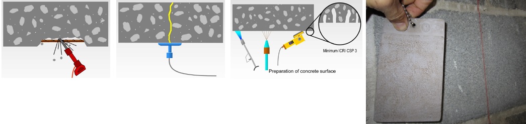
Of course, before any concrete or masonry reinforcement project can succeed, proper surface preparation is of the utmost importance. Without a good bond with the substrate, a composite will not be able to achieve the intended performance. Concrete voids must be repaired, cracks must be injected and sealed, and any deteriorated rebar must be cleaned and coated. Prior to composite placement, the surface of the substrate must be prepared to CSP-3 (concrete surface profile) in accordance with ICRI Guideline No. 310.2. Grinding and blasting are the most common surface-preparation techniques.
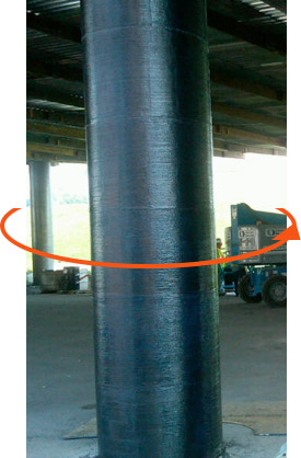
The following are just a few applications where composites can be used for concrete and/or masonry retrofits. The orange arrows show the direction of the fibers in the fabric – in other words, the direction in which the composite provides tension reinforcement.
This is a summary of the basics of composites and their installation on strengthening projects. As composites are not yet in the design codes in the United States, the American Concrete Institute has produced 440.2R-08: Guide for the Design and Construction of Externally Bonded FRP Systems for Strengthening Concrete Structures. This guide has numerous recommendations for using fiber-reinforced polymer systems to strengthen your concrete or masonry construction.
If you would like more information about FRP design, you can learn the best practices for fiber-reinforced polymer (FRP) strengthening design during a recorded webinar offered by Simpson Strong-Tie Professional Engineers. We look at FRP components, applications and installation. We also take you behind the scenes to share the evaluation process informing a flexural beam-strengthening design example and talk about the assistance and support Simpson Strong-Tie Engineering Services offers from initial project assessment to installation.
In this free webinar we dive into some very important considerations including the latest industry standards, material properties and key governing limits when designing with FRCM.
Continuing education credits will be offered for this webinar. Participants can earn one professional development hour (PDH) or 0.1 continuing education unit (CEU).
For complete information regarding specific products suitable to your unique situation or condition, please visit strongtie.com/rps or call your local Simpson Strong-Tie RPS specialist.
Modern code-listed adhesive anchors offer high-strength connection solutions for a variety of applications. However, as in all construction projects, good product performance requires proper selection and installation. In this blog post, we will discuss the challenge of installation orientation and an accessory that can help installers more easily make proper adhesive anchor installations—the piston plug adhesive delivery system.
ACI 318-11 Appendix D (Anchoring to Concrete) calculations use a uniform bond stress model to calculate an adhesive anchor’s resistance to bond failure. According to this theory, an adhesive anchor is assumed to transfer applied loads into the concrete base material uniformly along its effective embedment depth, hef. The equation for an anchor’s basic bond strength (expressed in pounds of force) is simply the adhesive formulation’s bond strength per unit area (λ * τcr) multiplied by the idealized cylindrical surface area of the insert that is in contact with the adhesive (π * da * hef):
Nba = λ τcr π da hef (ACI 318-11, Eq. D-22)
Although the model is a simplification of reality, the mathematical expression represents the core assumption that the adhesive is able to transfer stress completely along the entire depth of the anchorage. This is a key requirement in installation: Anchoring adhesives must be installed such that air entrapment and significant voids are prevented.
Downward installations (Figure 1) have historically presented relatively few challenges for adhesive injection in this regard. In such applications, gravity is helpful; the adhesive naturally flows to the bottom of the drilled hole while being dispensed from the cartridge through a static mixing nozzle. The installer maintains the open end of the nozzle below the free surface of the adhesive until the drilled hole is filled to the desired level. For deep holes, extension tubing is affixed to the open end of the nozzle to increase reach. This procedure avoids entrapping air bubbles in the adhesive material.
Figure 1 – Downward installation orientation
Installations into horizontal, upwardly inclined or overhead drilled holes (Figure 2) require more care on the part of adhesive anchor installers. Although the installation principle to avoid entrapping air is similar for these orientations, a key difference is that gravity does not help to keep the adhesive towards the “bottom” (deepest point) of the drilled hole. At worst, it can work against the installer when ambient temperatures may cause the adhesive to run out of the hole during injection. These adhesive anchor installations can be more difficult for an untrained installer and can slow the rate of work. This is one of the reasons that ACI 318-11 Section D.9.2.4 requires continuous special inspection of adhesive anchor installations in these three orientations when the application is also intended to resist sustained loads.
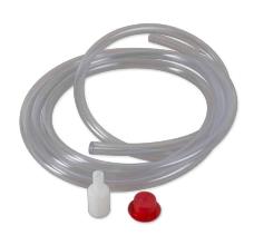
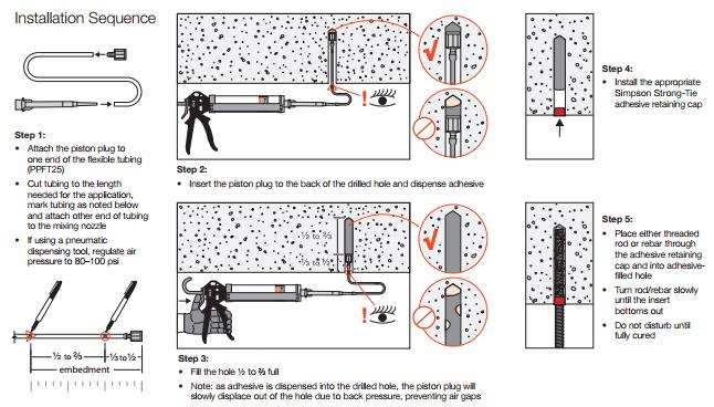
To aid the installer, Simpson Strong-Tie offers a piston plug adhesive delivery system (Figure 3). Consisting of pre-packaged flexible tubing, piston plugs and an adhesive retaining cap, this system allows installers to more easily and consistently make high-quality installations while completing their work efficiently. The installation sequence is provided in Figure 4.
Figure 3 – Piston plug delivery system
The system consists of three components:
Piston plug – The key component of the system, it is slightly smaller in diameter than the drilled hole. As the adhesive is dispensed into the drilled hole, the piston plug is displaced out of the hole by the advancing volume of the injected adhesive. The displacement creates a more positive feel for the installer to know where the free surface of the adhesive is.
Flexible tubing – For use with the piston plug to facilitate injection at the deepest point of the drilled hole.
Adhesive retaining cap – Provided to prevent adhesive material from flowing out of the drilled hole after dispensing and to provide a centering mechanism for the insert. For heavy inserts in overhead conditions, other means must be provided to carry the weight of the insert and prevent it from falling or becoming dislodged from the hole before the adhesive has fully cured.
Figure 4 – Installation sequence
What do you think about the piston plug adhesive delivery system? Let us know by posting a comment below.
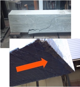
A deck and porch study reported that 33% of deck failure-related injuries over the 5-year study period were attributed to guard or railing failures. While the importance of a deck guard is widely known, there was a significant omission from my May 2014 post on Wood-framed Deck Design Resources for Engineers regarding the design of deck guards.
A good starting point for information about wood-framed guard posts is a two-part article published in the October 2014 and January 2015 issues of Civil + Structural Engineer magazine. “Building Strong Guards, Part 1” provides an overview of typical wood-framed decks, the related code requirements and several examples that aim to demonstrate code-compliance through an analysis approach. The article discusses the difficulties in making an adequate connection at the bottom of a guard post, which involve countering the moment generated by the live load being applied at the top of the post. Other connections in a typical guard are not as difficult to design through analysis. This is due to common component geometries resulting in the rails and balusters/in-fill being simple-supported rather than cantilevered. “Building Strong Guards, Part 2” provides information on the testing approach to demonstrate code-compliance. Information about code requirements and testing criteria are included in the article as well.
Research and commentary from Virginia Tech on the performance of several tested guard post details for residential applications (36” guard height above decking) is featured in an article titled “Tested Guardrail Post Connections for Residential Decks” in the July 2007 issue of Structure magazine. Research showed that the common construction practice of attaching a 4×4 guard post to a 2x band joist with either ½” diameter lag screws or bolts, fell significantly below the 500 pound horizontal load target due to inadequate load transfer from the band joist into the surrounding deck floor framing. Ultimately, the research found that anchoring the post with a holdown installed horizontally provided enough leverage to meet the target load. The article also discussed the importance of testing to 500 pounds (which provides a safety factor of 2.5 over the 200-pound code live load), and the testing with a horizontal outward load to represent the worst-case safety scenario of a person falling away from the deck surface.
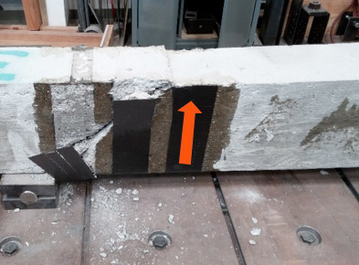
Simpson Strong-Tie has tested several connection options for a guard post at the typical 36” height, subjected to a horizontal outward load. Holdown solutions are included in our T-GRDRLPST10 technical bulletin. In response to recent industry interest, guard post details utilizing blocking and Strong-Drive® SDWS TIMBER screws have been developed (see picture below for a test view) and recently released in the engineering letter L-F-SDWSGRD15. The number of screws and the blocking shown are a reflection of the issue previously identified by the Virginia Tech researchers – an adequate load path must be provided to have sufficient support.
SDWS Detail C: Interior Post on Rim Joist between Joists, at 500-Pound Horizontal Test Target Load
Have you found any other resources that have been helpful in your guard post designs? Let us know by posting a comment.
We use cookies on this site to enhance your user experience. By clicking "I AGREE" below, you are giving your consent for us to set cookies. Privacy PolicyI AGREE
Privacy & Cookies Policy
Privacy Overview
This website uses cookies to improve your experience while you navigate through the website. Out of these cookies, the cookies that are categorized as necessary are stored on your browser as they are essential for the working of basic functionalities of the website. We also use third-party cookies that help us analyze and understand how you use this website. These cookies will be stored in your browser only with your consent. You also have the option to opt-out of these cookies. But opting out of some of these cookies may have an effect on your browsing experience.
Necessary cookies are absolutely essential for the website to function properly. This category only includes cookies that ensures basic functionalities and security features of the website. These cookies do not store any personal information.
Any cookies that may not be particularly necessary for the website to function and is used specifically to collect user personal data via analytics, ads, other embedded contents are termed as non-necessary cookies. It is mandatory to procure user consent prior to running these cookies on your website.


 The most cost-effective Simpson Strong-Tie shrinkage compensation device is the RTUD. This device has the smallest number of components and allows the rod unlimited travel through the device. It is ideal at the top level of a rod system run or where small rod diameters are used. Simpson Strong-Tie RTUDs can now accommodate 5/8″ (RTUD5) and ¾” (RTUD6) diameter rods.