This is Part 1A of a four-part series I’ll be doing on how connectors, fasteners, anchors and cold-formed steel systems are load rated.
I envisioned doing a four-part series on how connectors, fasteners, anchors, and cold-formed steel are load rated. After writing the first installment on connectors, I realized that connectors are a bit more complicated, since the testing and evaluation for joist hangers (or similar devices) is different than testing for holdown devices. And I wanted to discuss holdowns. So without belaboring the apology for my numbering system, this will be part 1A of the series – still discussing wood connectors, but focusing on holdowns and some of the unique requirements in their load rating.
AC155, Acceptance Criteria for Hold-Downs (Tie-Downs) Attached to Wood Members, was first developed in 2005 to better address boundary conditions, deflection limits, and wood post limits. Prior to AC155, holdowns were evaluated based on testing on a steel jig with a safety factor of 3.0 and an NDS bolt calculation. Deflection at the allowable load was simply reported so that it was available for use in design, but there was not a deflection limit that affected the load rating.
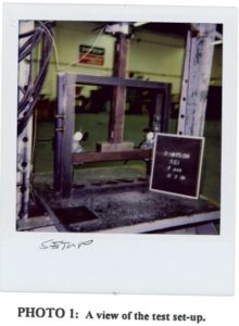
In the steel jig setup shown, the jig keeps the holdowns stationary while the rectangular bar underneath the holdowns is pushed downward to simulate an uplift force. This was (and still is) an effective method of testing the capacity of the steel body of a holdown, but it does not tell you a lot about the deflection of the holdown when installed on a wood member. Since story-drift is such a critical component to shearwall performance and the deflection of holdowns has a significant effect on the total drift, this needed to be address in the holdown test standard.
Continue Reading
Category: Testing/R&D
Simpson Strong-Tie is constantly testing and innovating.
Out-of-Plane Wall Anchorage Design
While the Simpson Strong-Tie Tye Gilb R&D lab in Stockton is a large testing facility, the world’s largest R&D lab is Mother Nature herself. Natural disasters such as earthquakes or storms put our engineering designs to the test. In this week’s blog post, I’ll be turning attention to wall anchorage for out-of-plane forces and the lessons we have learned from Mother Nature so far.
The 1979 building code incorporated many of the lessons learned from the 1971 San Fernando earthquake. In 1994, Mother Nature put the 1979 building code to the test with the January 17 Northridge earthquake. The Northridge earthquake showed that some of the increased design and detailing requirements in the 1979 building code worked well to improve performance over what was observed in 1971. However, it also revealed to researchers that acceleration at the roof level of single story warehouse buildings were three to four times the ground acceleration. The combination of higher than expected acceleration and excessive deformation of the wall anchorage assembly caused many wall anchorage failures.
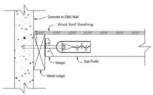
Several changes in the design forces used for wall anchorage and additional detailing requirements were incorporated in the 1997 Uniform Building Code. The requirements have been refined with each new building code, but overall the requirements and design forces have remained about the same under the current International Building Code. Wall anchorage design is governed by ASCE 7-05 and ASCE 7-10 Section 12.11. These provisions aim to mitigate the brittle wall anchorage failures observed in past earthquakes by increasing the design force and in Seismic Design Categories C through F, requiring:Continue Reading
So, What’s Behind A Structural Connector’s Allowable Load?
This is Part 1 of a four-part series I’ll be doing on how connectors, fasteners, anchors and cold-formed steel systems are load rated.
Today I did my presentation for the WoodWorks webinar on Testing and Product Evaluation of Products for Wood-framed Construction. We covered a lot of material regarding code requirements for using alternate materials or construction methods, how testing and evaluation criteria are developed, and some specifics on several Acceptance Criteria (AC’s) that are commonly used for connector evaluations. We also discussed some specific testing requirements, so I thought it would be timely to discuss some of those issues in this week’s blog post.
So, how are structural connectors for light frame wood construction load rated? What’s behind the allowable loads information published in Simpson Strong-Tie literature or wood connector evaluation reports? These are things that you might find yourself wondering while driving to the office or jobsite, or on a Sunday afternoon while enjoying your favorite iced tea or barley-based beverage.
The short answer is: testing, calculations, and of course, sound engineering judgment.
So, What's Behind A Structural Connector's Allowable Load?
This is Part 1 of a four-part series I’ll be doing on how connectors, fasteners, anchors and cold-formed steel systems are load rated.
Today I did my presentation for the WoodWorks webinar on Testing and Product Evaluation of Products for Wood-framed Construction. We covered a lot of material regarding code requirements for using alternate materials or construction methods, how testing and evaluation criteria are developed, and some specifics on several Acceptance Criteria (AC’s) that are commonly used for connector evaluations. We also discussed some specific testing requirements, so I thought it would be timely to discuss some of those issues in this week’s blog post.
So, how are structural connectors for light frame wood construction load rated? What’s behind the allowable loads information published in Simpson Strong-Tie literature or wood connector evaluation reports? These are things that you might find yourself wondering while driving to the office or jobsite, or on a Sunday afternoon while enjoying your favorite iced tea or barley-based beverage.
The short answer is: testing, calculations, and of course, sound engineering judgment.
Continue Reading
Join Me for a WoodWorks Webinar on Acceptance Criteria and Testing Methods for Connectors
I have the privilege of presenting a free WoodWorks webinar, “Testing and Product Evaluation of Products for Wood-framed Construction” on Thursday, October 25 at 10 am PST. Here is the webinar description:
Products that are not covered by the code are used in many if not all buildings. While the code permits a single engineer to review and submit to a building official and a single building official to review and approve a product not covered by the code, many feel a more robust process is needed to ensure that these products meet the code intent. Also, many code or evaluation reports are used not just for one project, but for multitudes of projects in numerous locations. Test setups can affect the performance and load rating of products.
Several private entities have been created over the years to assist the industry by developing public and transparent processes to develop test requirements, load rating requirements, design and detailing requirements, and ongoing quality compliance as well as product evaluation methodologies. This webinar will discuss various acceptance criteria and testing methods used for products used in wood construction, such as ASTM D7147 and ICC-ES AC155 to further advance the knowledge of these test methods and processes for those in the wood construction industry.
This will be a great opportunity for those of us who work in wood frame construction to discuss code and test requirements for connectors and other products for wood. I hope you’ll consider joining us! To register for the webinar, click here.
– Paul
What are your thoughts? Visit the blog and leave a comment!
Designing Steel Roof Deck Attachment for Combined Tension and Shear
In last week’s post I made a reference to California’s golden sunshine. Californians may have to deal with wildfires, earthquakes, and wearing sunscreen year round, but we generally don’t have high wind to worry about. In a previous blog post, Roof Deck Design Considerations for High Wind Events, I discussed some of the general challenges in designing for wind uplift. This week, I wanted to get a little more specific and discuss the standards applicable to steel roof deck attachments.
Historically, procedures for design of structural connections that utilize fasteners recognize the importance of combined loading effects on structural performance. Whether bolts or screws are the connector choice, the metallic structure of steel alloys includes transverse slip planes of relatively low resistance. This results in yield criteria (function that defines the onset of yielding or fracture) that are often limited by load-deformation performance along transverse planes.
What’s Most Important To You As A Structural Engineer?
I am attending the 2012 SEAOC-SEANM Convention in Santa Fe, New Mexico this week. I did not realize that Santa Fe is the oldest state capitol in the U.S., first inhabited by Spanish settlers in 1607, and then settled by Don Pedro de Peralta in 1609-1610. The Palace of the Governors, built in 1610, served as the main government building in Santa Fe for nearly 300 years. The current capitol building, known as the Roundhouse, is the only round state capitol building in the U.S. Our airport shuttle driver used to be a tour guide, so we learned a lot on the drive in.Continue Reading
What's Most Important To You As A Structural Engineer?
I am attending the 2012 SEAOC-SEANM Convention in Santa Fe, New Mexico this week. I did not realize that Santa Fe is the oldest state capitol in the U.S., first inhabited by Spanish settlers in 1607, and then settled by Don Pedro de Peralta in 1609-1610. The Palace of the Governors, built in 1610, served as the main government building in Santa Fe for nearly 300 years. The current capitol building, known as the Roundhouse, is the only round state capitol building in the U.S. Our airport shuttle driver used to be a tour guide, so we learned a lot on the drive in.

The first session I attended today was a discussion of recent earthquakes. James Mwangi Ph.D, PE, Associate Professor of Architectural Engineering at Cal Poly, discussed his project to develop sustainable reconstruction practices for masonry and concrete structures in Haiti following the 2010 earthquake. Then Joe Maffei, Ph.D, SE, talked about lessons learned about concrete wall design from the 2010 Chile earthquake.
Continue Reading
A Little Fun with Testing
My apologies for being late with my blog post this week. We are having our once a year big sales meeting, so I’ve been traveling to the Midwest to participate. Speaking of traveling, several times each year, we invite our newest employees to our home office in Pleasanton, California for a week-long Sales and Product Orientation class. Although originally envisioned as detailed product knowledge training for our sales people, the class has evolved over the years to include people from all areas of our business such as finance, accounting, IT, purchasing, quality, marketing, and (of course) engineering.
I do one presentaton for the class explaining the importance of a continuous load path in a building, and another covering the history of innovation that led to some of our products. It is a great opportunity for me to meet my new coworkers by spending some time with them before they embark on their careers in different parts of the country (or world!).
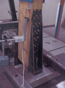
My favorite training session I do for the class is about product development and testing, which includes a tour of our test lab in Pleasanton. We go over a lot of testing basics – how we select lumber, get parts made, build setups and run the tests. For a demonstration, I used to run a simple joist hanger test and also a holdown test. Usually I’ll pick a heavy holdown to test, since those make an impressive bang when the steel breaks, and then everyone jumps and gets a good laugh out of it.
How We Test – Part I: Wood Connectors
If you have followed some of my earlier blog posts, you know I am passionate about testing. In my post, Testing – Then and Now, I said, “There simply is no substitute for a physical test.” Something I haven’t discussed in much detail, however, are some of the complexities involved in a good test.
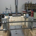
For wood connector testing, we follow ASTM D7147-11 Testing and Establishing Allowable Loads of Joist Hangers. The actual testing is relatively straight forward – build at least three setups, test them, measure the deflection and ultimate loads.
