


Welcome to our second Anchor Anatomy 101 blog post focusing on anchor systems. Each post is designed to clarify anchor components, installation processes, and common applications to help you make informed anchor selection decisions based on your project’s unique requirements. Our first article focused on screw anchors; this blog looks at adhesive anchoring systems.
Post-installed concrete and masonry adhesive anchors consist of a combination of adhesive and threaded rod or reinforcing steel anchor inserts. This combination provides for the ultimate in design flexibility, jobsite versatility, and exceptional performance. In addition, adhesive anchoring systems are often selected by designers and contractors for their ICC-ES evaluation reports, load–carrying capacities, and ease of installation. All three adhesive anchoring solutions in the Simpson Strong-Tie “3G” adhesive family have obtained evaluation reports, published by ICC-ES or IAPMO-UES, which are often necessary to gain building officials’ approval. Let’s take a closer look at the anatomy of the SET-3G® high–strength epoxy adhesive anchoring system (Figure 1).

- Adhesive: This two-component product is the critical agent bonding the steel anchor element to the concrete or masonry substrate. The adhesive fills the voids between the concrete and the anchor, ensuring maximum surface contact and consequent load resistance after it is fully cured. SET-3G epoxy adhesive is an injectable, two-component, 100%-solids, epoxy-based adhesive mixed at a 1-to-1 volume ratio of hardener-to-resin. The two chemicals combine as they move through the static mixing nozzle element. SET-3G is available in 8.5-ounce, 22-ounce, and 56-ounce cartridges. The shelf life of SET-3G in unopened cartridges is two years from the date of manufacture when stored at temperatures between 45°F and 90°F. The expiration date is printed on the cartridge label and should be verified before use.
- Static Mixing Nozzle: Figure 1 shows the mixing nozzle, width, shape, and internal helical-shaped mixing element. The static mixing nozzle is exclusive to the adhesive anchor system. The unique nozzle mixing element design ensures a proper ratio of the hardener and resin materials as they are pushed through the nozzle length by the dispensing tool. The initial mixed adhesive material is dispensed off to the side until a uniform, solid-color material is visible. A visibly uniform color confirms a proper mixture. SET-3G is gray in color when properly mixed.
Steel Anchoring Element: Either nonproprietary threaded steel rod, proprietary ATR (all thread rod), or deformed reinforcing steel (rebar) is used to transfer the load from the fixture to the substrate. (See Figure 2 for standard nonproprietary steel types allowed by ESR reports.) Inserts develop a strong mechanical interlocking bond to the adhesive. The adhesive in-turn chemically bonds to the concrete or masonry substrate completing the continuous load path. Threaded steel anchor rods must be carbon steel or stainless steel, clean, oil-free, straight, and free of indentations or other defects along their lengths. They must be continuously threaded rod (all-thread) having thread characteristics complying with ANSI B1.1 UNC coarse thread series. The embedded length of steel rebar must be straight and free of mill scale, rust, mud, oil, and other coatings that may impair the bond to the adhesive. Rebar is allowed to be used for either post-installed anchorage or post-installed rebar doweling type connections. Rebar design development and splice lengths are determined by ACI 318 Chapter 25 provisions. If you haven’t seen it, check out our Web App for RDLC calculations.

4. Steel Screen Tubes: For unreinforced clay brick masonry (URM) substrates only, a steel screen tube was used in testing to guarantee performance of the anchor system (Figure 3). The screen tube prevents adhesive from spilling into voids in the mortar and keeps the brick from absorbing all the adhesive around the anchor, ensuring a proper bond to both the anchor insert and the interior of the brick and mortar. The steel mesh spacing is designed to allow only the right amount of adhesive to flow through the screen tube to bond with the URM. The screen tube SKU and mesh size are unique to the adhesive and substrate. For example, ET-3G™ epoxy adhesive requires the plastic ETS screen tube (ETSxxxP) for hollow masonry substrates and the carbon–steel screen tubes (ETSxxx) for unreinforced masonry (URM). See our other SE Blog post, “Which Anchoring Adhesive Installation Method Is Faster: A Comparison of Core Drilling vs. Carbide Drilling into URM” for more information.

5. Opti-Mesh Screen Tube: For hollow CMU substrates only, a screen tube is essential for the overall performance of the anchor system (Figure 4). The screen tube’s integral cap, flanges, and open-mesh collar limit the adhesive around the anchor, ensuring a proper bond to the anchor insert and face shell, while positioning the anchor in the center of the hole and in contact with the face of the wall. The integral cap displays the anchor rod diameter, drill bit diameter, and the Simpson Strong-Tie “≠” symbol for inspection after installation. The space between the woven mesh insert and the plastic screen tube is designed to allow only the right amount of adhesive to flow through the screen tube to bond with the base material while the balance remains in the screen to bond the anchor rod. The screen tube SKU, color, and mesh size are unique to the adhesive. For example, SET-3G® requires a grey screen tube (3GWSxxxP) while ET-3G™ (EWSxxxP) is used with a black screen tube.

Installation Steps
The images shown in Figures 5, 6, and 7 are for a vertically oriented installation using a coaxial cartridge of SET-3G® adhesive, a standard threaded rod anchor, solid concrete substrate, and dry/damp hole. Please visit Strongtie.com for additional adhesive anchor installation types and requirements. Prior to installation, always confirm the product expiration date and determine the concrete substrate temperature. SET-3G requires a minimum substrate temperature of 40°F and a maximum of 100°F during the entire cure time.
Hole Preparation
- Drill: Installation starts with drilling a pilot hole using a rotary hammer drill with a standard carbide-tipped drill bit (ANSI B212.15) to the specified nominal embedment depth. The drill bit diameter varies and ranges from 1/16″ to 1/8″ larger than the nominal anchor diameter. See strongtie.com for drill bit diameter requirements.
- Blow: The hole is blown with oil-free compressed air for a minimum of two seconds to remove dust and debris. The compressed air nozzle must be long enough to reach the bottom of the hole.
- Brush: The hole is manually cleaned using a steel wire brush and two vertical strokes. The brush must reach the bottom of the hole on each stroke.
- Blow: The hole is blown with oil-free compressed air again for a minimum of 2 seconds to remove any remaining dust and debris. The compressed air nozzle must be long enough to reach the bottom of the hole.

Figure 5 – Hole Preparation Coaxial Cartridge Preparation
- Check: Read the expiration date on the cartridge label. Do not use an expired product.
- Open: Turn the cap counterclockwise to remove, then remove plastic plug. No cutting required.
- Attach: Screw the static mixing nozzle onto the threaded end.
- Insert: Place cartridge into dispensing tool.
- Dispense: Using dispensing tool, dispense adhesive off to the side until the color is uniform, indicating a proper mix.
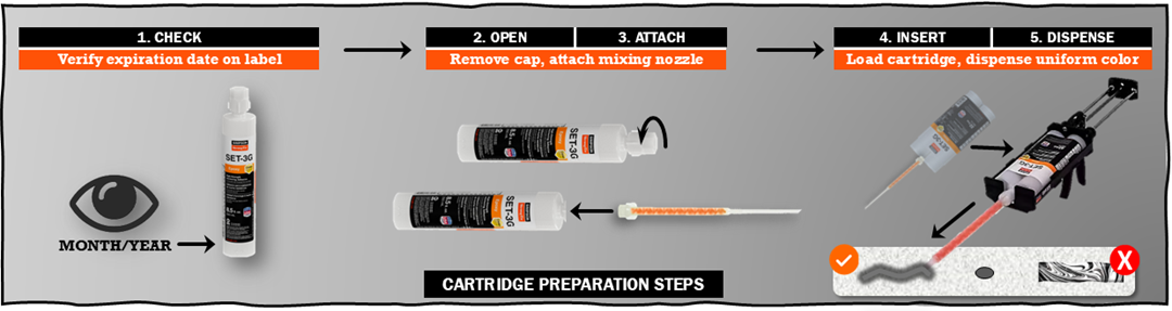
Figure 6 – Cartridge Preparation Filling the Hole
- Fill: Insert the mixing nozzle tip down to the bottom of the hole and dispense adhesive while slowly withdrawing the nozzle. Holes should be filled with adhesive from about half full to 2/3 full.
- Insert: Slowly push and turn the anchor insert clockwise down until it contacts the bottom of the hole.
- Do not disturb: Leave insert and adhesive alone until the full required cure time has been reached.


Typical Adhesive Anchor System Applications
Adhesive anchors are used in a variety of structural applications for attaching threaded rods and reinforcing bars to concrete and masonry base materials. Adhesives can be installed vertically, overhead, upwardly inclined, or horizontally to resist uplift, shear, and tension loads. They typically have smaller edge distance and anchor spacing requirements than mechanical anchors. These anchors are helpful in addressing situations where cast-in-place (CIP) anchors are missing, damaged, or incorrectly located and are often in retrofit and renovation projects. Figure 8 highlights some adhesive anchor application examples per market sector.

Conclusion
Post-installed adhesive anchor systems utilizing threaded rod or rebar anchors are a versatile and high-performing solution for structural connections to concrete and masonry elements. By understanding the individual system components, installation process, and structural applications, you can confidently select, design, and specify the appropriate anchor type to meet your project’s challenges. Stay tuned for the next Anchor Anatomy 101 blog post featuring mechanical expansion (wedge) anchors. For any questions about anchoring products or project applications, please contact your local Simpson Strong-Tie field engineer.
