


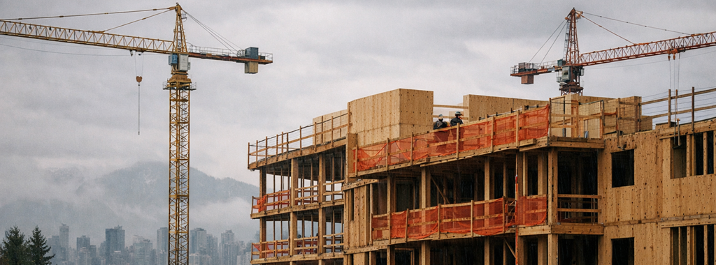
When I graduated from university in 2013, British Columbia had already been allowing six-storey light-frame wood buildings via its provincial building code for a few years. Shortly thereafter, I joined Simpson Strong-Tie and became more familiar with practices in the other western provinces (Alberta, Saskatchewan, and Manitoba) which took a bit longer to embrace these six-storey structures. Over the past twelve years, it’s been interesting to watch their popularity rise due to increased demand for housing and sustainability, with the industry’s confidence growing alongside this evolution.
Colloquially referred to as “mid-rise,” these buildings have their own set of design and construction considerations. More storeys mean higher seismic and wind forces, shearwalls must resist larger overturning demands, and cumulative deflection becomes a more important design consideration. In addition, multistorey wood structures are more affected by material properties such as shrinking and settling, which must be accounted for to ensure performance during their lifecycle.
NBCC 2020
More recently, Part 4 of the 2020 edition of the National Building Code of Canada (NBCC) received major updates to its seismic provisions. We’re now seeing the impact as each province adopts this into their own provincial code updates (for example, British Columbia in 2024). For context, Part 4 covers any building greater than three storeys or 600 square meters (6,460 square feet), while any building smaller than that falls under the category of Part 9. In short, these changes have intensified the above-mentioned challenges associated with mid-rise construction.
The increases in seismic hazard values stem from several sources. Recently available data have allowed researchers to update ground motion models (GMMs), which predict the level of ground shaking using recorded motions from regions with similar tectonic conditions. More recent GMMs also implement the average shear wave velocity in the immediate 30 meters below the ground (98 feet, and commonly denoted as “Vs30”). Additionally, events like the Christchurch earthquake in 2011 have popularized the concept of seismic resilience — designing buildings not just to avoid collapse, but also to limit the damage and repair work needed after the event.
Anecdotally, in meetings with hundreds of structural engineering consultants over the last couple of years, I’ve found these changes to be a frequent topic of discussion. Force magnitude depends heavily on geographic location and site conditions, with most engineers estimating that local shear forces have increased in the range of 10% to 40%. As expected, coastal regions such as Vancouver Island are experiencing trends at the higher end of that range. With regard to shearwalls and their holdowns, in many cases this means going bigger.
Traditional Holdowns
Holdowns have traditionally been used to anchor each end of a shearwall to the concrete below to help it resist overturning, racking, and sliding. They’re generally cost-effective, familiar to installers, and straightforward to detail and inspect. Below is a picture of a Simpson Strong-Tie® HDUE™ holdown connector, which was recently introduced in 2025 to replace the older iteration called HDU.

As an example, the largest model HDUE17 has a maximum factored resistance of 21,000 lb. (94 kN) when fastened to Douglas fir studs, or a maximum of 18,000 lb. (80 kN) when fastened to spruce-pine-fir. This is effectively the cutoff point for traditional holdowns, and beyond that an alternative method would have to be considered (such as a continuous rod tiedown system, which is described later below). Resistance demand is the primary criterion for choosing one of these methods over another.
In Canada, the limit for lateral deflection of a building is determined by NBCC, and there are numerous factors contributing to that determination. One of the components of the deflection calculation is denoted as “da,” which is defined as the total vertical elongation of the wall anchorage or holdown system. When loaded to its maximum factored resistance, the HDUE17 holdown deflects 0.128″ (3.3 mm), which can be linearly interpolated for lower demand levels. This is less than its previous iteration, the HDU14, which has been phased out. This reduction is beneficial because we want to minimize the amount that vertical elongation contributes to our shearwall deflection.

However, it should be noted in the table that not every HDUE connector deflects less than its HDU counterpart. There are also a few cases where the factored resistance of an HDUE is slightly less than an HDU, most notably in the replacement of the HDU8 with the HDUE9 when attached to wood of 4 1/2″ (114 mm) thickness. Please note there are further footnotes and information about HDUE design values available in this engineering letter.
Rod Systems
When factored tensile load exceeds the limits of the above-mentioned holdowns, we must look at alternative methods such as rod systems (also known as continuous anchor tiedown systems or ATS). They can be thought of as “heavy-duty” holdowns that usually run from the foundation to the upper level, tying down every storey in between. Much of the information referenced in the following paragraphs can be found in our design guide for the Canadian market .

Twelve years ago, the maximum diameter of rod I would see was 1 1/8″ (29 mm). These days, because of changes to the building codes, we’re frequently seeing 1 1/2″ (38 mm) diameters and sometimes even 2″ (51 mm) diameters being used. For context, a 2″-diameter threaded rod made of high-strength steel (ultimate strength, Fu = 125,000 psi or 860 MPa) has a factored resistance of 234,000 lb. (1,040 kN).
While these values are proportioned to the scale of forces these systems need to accommodate, the rod sizes are often purposely oversized to reduce deflection. The amount of deflection is calculated with the equation PL/AE, where P is the axial load, L is the initial rod length between restraints at the storey under consideration, A is the net tensile area of the rod, and E is the constant modulus of steel (29,000,000 psi or 200,000 MPa). As a result, upsizing the diameter increases “A” in the denominator of the equation, hence reducing deflection. Anecdotally, we see these threaded rods generally deflect in a similar range to the traditional holdowns mentioned in the previous section — so roughly in the 0.1″ to 0.3″ ballpark (2.5 mm and 7.6 mm respectively), depending on the factors in the equation.
With rod systems, there’s a further consideration for calculating deflection as well, which is the take-up devices (TUDs). The main purpose of TUDs is to adjust for the fact that steel doesn’t shrink like wood does — further information can be found in a previous SE Blog post (https://seblog.strongtie.com/2016/02/shrinkage-compensation-devices/). Ratcheting take-up devices (RTUDs) are illustrated to the left below, and pin-activated take-up devices (ATUDs) are to the right.

ATUDs require a pin to be pulled for their spring to activate, which is an extra step to consider on the jobsite, and for that reason installers often prefer RTUDs. However, ATUDs generally deflect less under loading (see the tables below), so they are sometimes preferred by engineers in their shearwall calculations. Please note that the seating increment (denoted as ΔR below) is a constant, which represents the initial movement of the ATUD’s spring activating or the RTUD’s ratcheting teeth engaging. Meanwhile, the deflection at factored resistance (denoted as ΔF) can be interpolated based on the actual loading, as with conventional holdowns. The seating increment and interpolated deflection shall be summed together, then accumulated at each level along with the rod deflection.

The NBCC 2020 seismic updates underscore the importance of selecting the right holdown system for multistorey wood construction. Conventional holdowns such as the HDUE remain an effective choice for smaller projects, while rod systems shine when higher capacities are required. Ultimately, the decision depends on the number of storeys, the expected loading, and the project goals.
We offer design guides and other resources to help you meet these new requirements with confidence. For a deeper dive into this topic, including detailed comparisons, design examples, and case studies, please don’t hesitate to reach out to Simpson Strong-Tie at (800) 999-5099.