


The anchorage of nonstructural components like mechanical and electrical equipment is an important element of ensuring life safety that doesn’t always get the same attention as the structural engineering required for the building itself. The key standard that governs design loads is ASCE 7. This blog post explores updated equations in the newest edition of the standard, ASCE 7-22, specifically Chapter 13, which covers seismic design of nonstructural components. We’ll walk step by step through an example of anchoring a piece of equipment to a concrete slab inside a Risk Category IV building in a high seismic area.
Design Example
Let’s go through this together and assume we need to anchor a piece of equipment (4′ x 2′ x 2′ tall) that weighs 2,000 lb. We’re attaching it to a concrete slab on metal deck inside the building. The ASCE 7 Hazard Tool is used to obtain design criteria. If you haven’t used this free online tool yet, it’s published by ASCE 7 and essential for determining design loads in accordance with the newest code (especially updated LRFD snow values, but I will save that for another blog post). If this were a real project, it would also be important to check with your Authority Having Jurisdiction (AHJ) to see whether they have any additional criteria or a local code to abide by, such as the California Building Code. Throughout the calculations, I will list values, references, and assumptions.
Load Development
The first thing that needs to be determined is which loads apply. I chose to anchor the component inside the building for this example so I could focus on seismic design. Wind and snow loading would play a role for equipment anchored outside the structure, and those loads would need to be determined in accordance with Chapters 7 and 29 in ASCE 7-22. I’ll soon publish a follow-up post that covers updates in these chapters as they pertain to loads on equipment attached to the outside of a building. It’s important to consider the location of the equipment relative to your structure when beginning your design. The figure below from ASCE 7 illustrates different locations of components to consider.

Now to focus on seismic loads. When looking at seismic design of equipment, many nonstructural components are exempt as detailed in ASCE 7 Table 13.1-1, including all mechanical and electrical components in Seismic Design Category (SDC) A & B. For this example, we are in high seismic area, SDC D. There are some situations in which you are exempt from seismic requirements for SDC D. However, these situations are tied to the weight of the component being less than 400 lb., and in this example I decided our component was heavy for its size and weighs 2 kips, so seismic loads need to be considered.
Seismic Load Development
Now that we’ve determined that seismic loads need to be developed, I need to go through Chapter 13 to calculate the horizontal design force, Fp, from Equation 13.3-1.
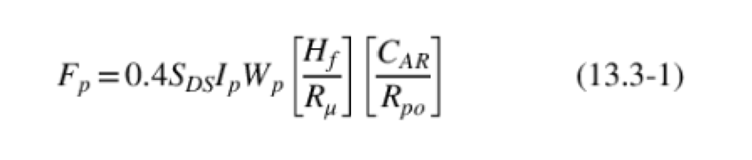
You may notice this equation looks quite a bit different from Equation 13.3-1 in ASCE 7-16 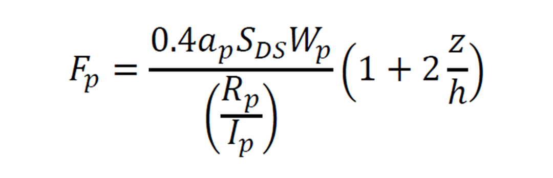
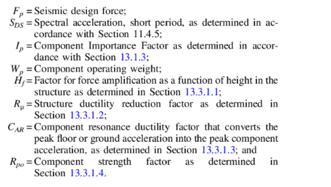
This new equation is due to research in the Applied Technology Council ATC-120 project that resulted in NIST GCR 18-917-43, Recommendations for Improved Seismic Performance of Nonstructural Components (2018). In this updated study, they investigated the effects of both building and component properties, including the seismic-force-resisting system (SFRS) of the building, modal period, ductility, and vertical location of the component within the building. New factors Rµ and CAR, which I will discuss later in more detail, have been added to the force equation based on the results of these studies.
Spectral Acceleration, SDS, and Component Weight, Wp
The spectral acceleration short period, SDS, is a property based on the building’s location. For our site, I’ll use an SDS = 0.80g, which is obtained from the ASCE 7 Hazard Tool. Typically, a value above 0.5g would be considered high. I covered the component weight, Wp = 2 kips, earlier in the blog.
Component Importance Factor, Ip
The Component Importance Factor, Ip, can be determined based on Section 13.1.3. This factor is unique to the component and is separate from the building’s seismic importance factor, Ie. It is tied to the performance requirements for a component based on the functionality of the structure to which it is attached.
Since our example is for equipment anchored in a Risk Category (RC) IV building, I referenced Section 13.1.3 and saw Ip = 1.5, when the component is required for continued operation of a structure designated as an Essential Facility. If your RC IV building is an Essential Facility (e.g., a hospital), the equipment is designed with an Ip of 1.5. Another example of a component designed with an Ip of 1.5 is fire sprinkler piping, since the system is essential for life safety.
Height Amplification Factor, Hf
This is a new term in the equation that relates the Ratio of Peak Floor Acceleration (PFA) to Peak Ground Acceleration (PGA) at different heights in the building. As you can see, Equation 13.3-4 includes building period.
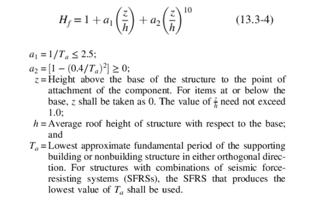
I am going to assume the SFRS is a buckling-restrained braced frame (BRBF) in both directions, and the building is 60‘ tall, so the Ta = 0.65 seconds according to Section 12.8. 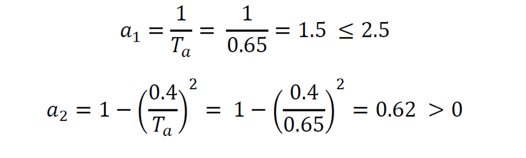
Let’s assume our component is anchored on the second floor, which is at about z = 12‘. 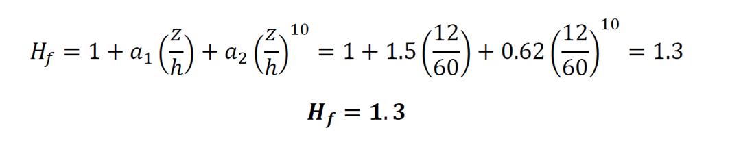
There is another equation in this section that allows you to calculate Hf when the building period is unknown, Equation 13.3-5. You’ll notice this term matches the end of the original equation from ASCE 7-16 where you used to multiply everything by this number. In essence, Hf has always existed, only now engineers can be more precise and include the building period in calculations.
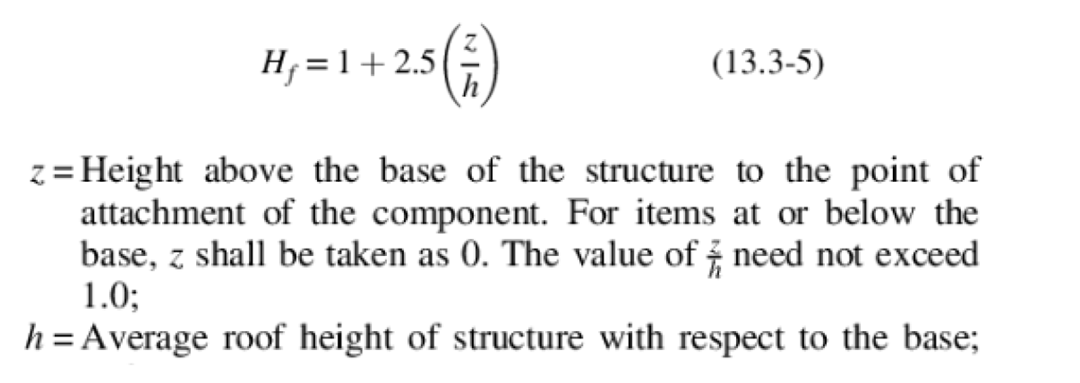
If we did not know our building’s period and instead used Equation 13.3-5 for our example, z/h = 12/60 = 0.2 and Hf =1.5. This approximation for Hf Hf is larger and would result in a larger overall seismic force and therefore a more conservative design.
Structure Ductility Reduction Factor, Rµ
This new factor is calculated per Equation 13.3-6 and is based on the SFRS of the structure the component is attached to, i.e., the building. This factor was added because studies found that increasing the building’s ductility generally reduced seismic demands on nonstructural components. We previously established that the SFRS is a BRBF system, where R = 8 and Ω0 = 2.5 per table 12.2-1. The building’s Importance Factor, Ie, is 1.5 per Table 1.5-2. Note that while this number does happen to be the same as Ip in this case, they are separate Importance Factors.
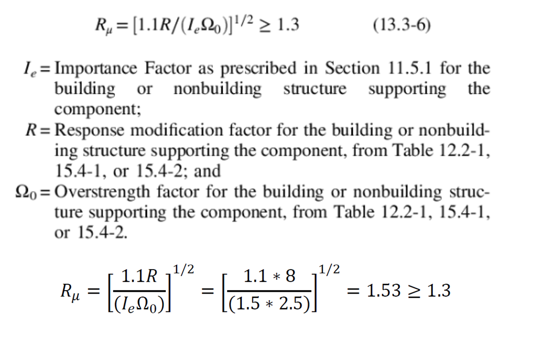
Note that if the SFRS is unknown and the component is located above the grade plane, Rµ can be taken as 1.3. When equipment is at or below the grade plane, Rµ is 1.0.
Component Resonance Ductility Factor, CAR, and Component Strength, Rpo
These two final new factors are all about the component itself instead of the structure. The first factor, 𝑪𝑨𝑹, is the relationship between the Peak Component Acceleration (PCA) to the Peak Floor Acceleration (PFA). This ratio is affected by both the building period and component ductility. When the period of the building and the component are similar, response is increased due to resonance. For this factor, a value of 1.0 indicates resonance is unlikely between the building and component whereas likelihood is increased with the value. Rpo is the reduction factor to account for the inherent overstrength of the component.
The values can be found in Table 13.5-1 for Architectural Components like cabinets, and Table 13.6-1 for Mechanical and Electrical Components. You’ll notice for mechanical and electrical equipment, 𝑪𝑨𝑹 is higher for components supported by integral supports, sheet metal, or skirts as these supports often have a lower ductility and a higher probability of overlap with the building period. Alternative 𝑪𝑨𝑹 values can be developed for components not listed in the table by conducting shake table component tests.
I am going to use the values for a generator, which are 𝑪𝑨𝑹=𝟏 𝑎𝑛𝑑 𝑹𝒑𝒐=𝟏.𝟓. From this table, we also obtain the overstrength factor, 𝛀𝒐𝒑=𝟐. This factor is required to apply to design forces for anchorage to concrete and masonry when complying with ACI 318-19 Section 17.10.5.3 (d) and 17.10.6.3 (c). This factor will be revisited shortly once we start evaluating the load combinations in the next section.
In previous versions of the code, the equation had the component amplification factor ap, and a response modification factor Rp relating to the component. While these factors also considered overstrength, deformability, and dynamic amplification, they have been removed since the release of ATC-120 results and the new equation.
Calculating Seismic Forces
Now that we have all our factors, we can calculate our seismic forces. We’ll start with the horizontal component, Fp:
We also need to check the minimum and maximum values according to Section 13.3: 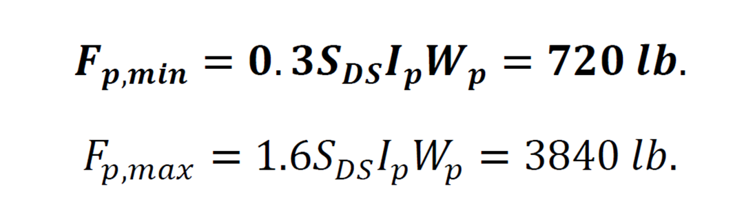
In this case, the minimum value controls for our horizontal force.
The vertical component of our seismic force is calculated according to Section 12.4.2.2: 
Anchoring Equipment
Determine Applied Loads
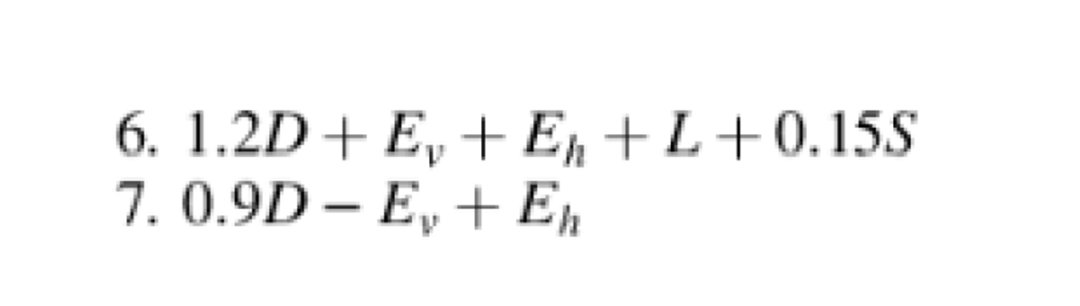
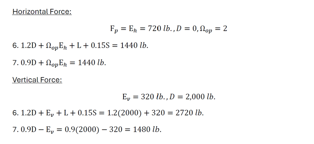
Now that we know what forces we’re dealing with, let’s move on to the next step for designing our anchorage: factoring loads. In concrete anchor design, we use LRFD load combinations in accordance with ACI 318-19 Chapter 17 which can be found in Section 2.3 of ASCE 7-22. Since this example component is anchored indoors, we only have seismic and dead loads we need to account for, so our controlling combination will be 6 or 7 from Section 2.3.6.
Furthermore, Section 13.4.2 indicates that seismic load effects including overstrength in Section 12.4.3 shall be applied.

Now for the load application, we reference Section 13.3.1, which describes the horizontal component of seismic to be applied at the center of gravity of the piece of equipment based on its mass distribution. This is typically provided by equipment vendors on cut sheets and is unique to the units themselves. For simplicity, I have placed the center of gravity at the center of this example generator, hcg = 2.5′ = 30″.
Section 13.3.1 also states the direction of Fp shall be that which produces the most critical load effects. Alternatively, it is permitted to look at 100% of the load in one direction and 30% in the other (Case 1), which I’ve opted to do for this example.
30% of 1,440 lb. (Vy) gives 432 (Vx) applied concurrently. 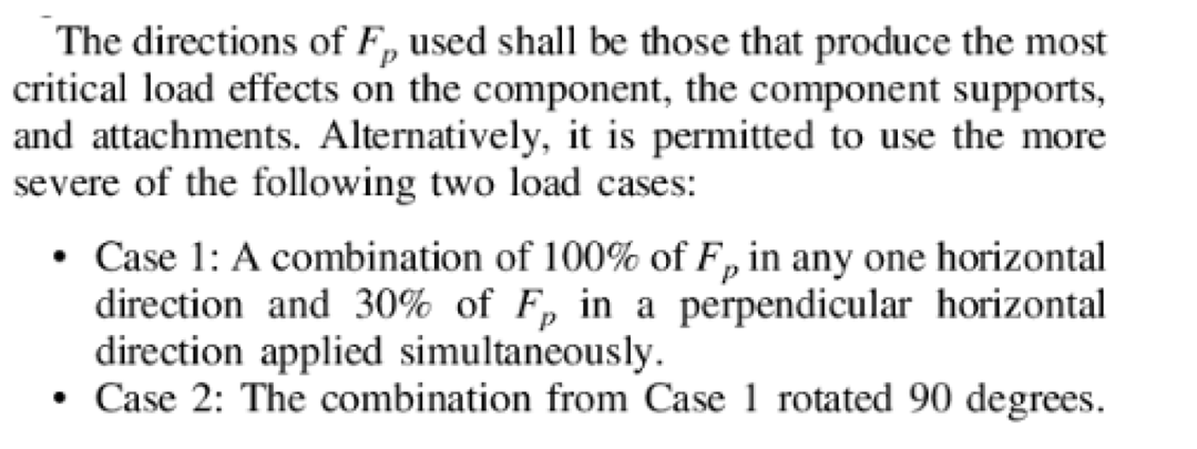
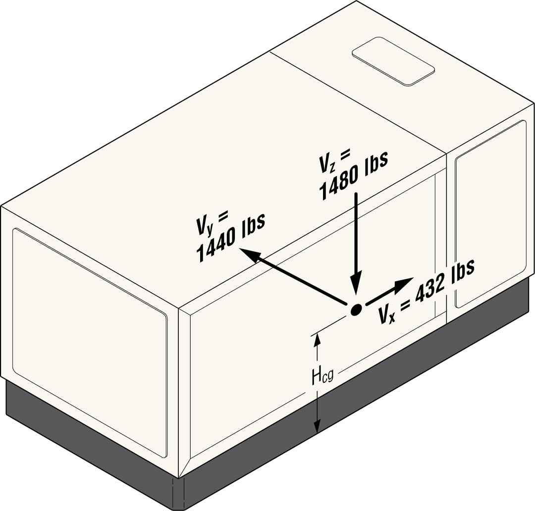
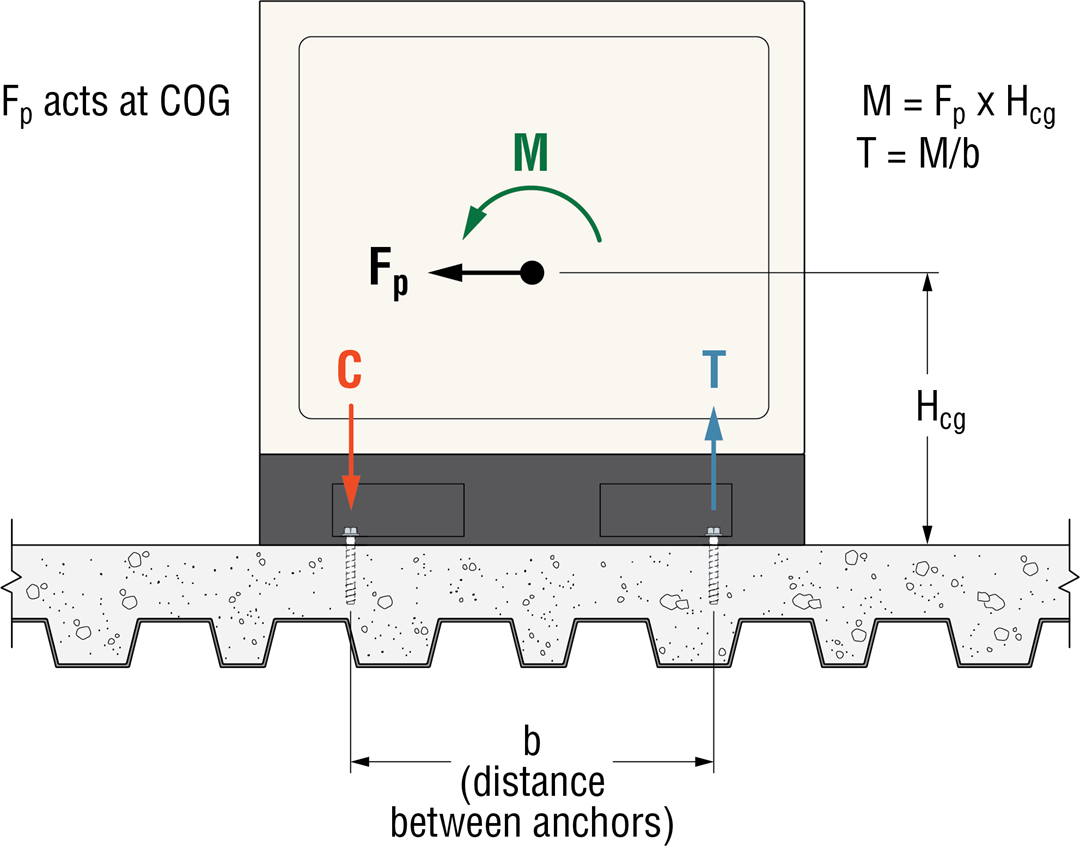
As these horizontal forces are applied at the center of gravity, when designing our anchors, anchor forces need to consider the loads resulting from an applied moment using the height of the center of gravity hcg as the moment arm.
My = 432 * 1 = 432 lb.-ft.
Mx = 1440 * 1 = 1,440 lb.-ft.
We can now move on to creating our anchor model in Simpson’s free Anchor Designer™ for Concrete (ADC) software. Below is a screen clip from the design result showing the applied loads.
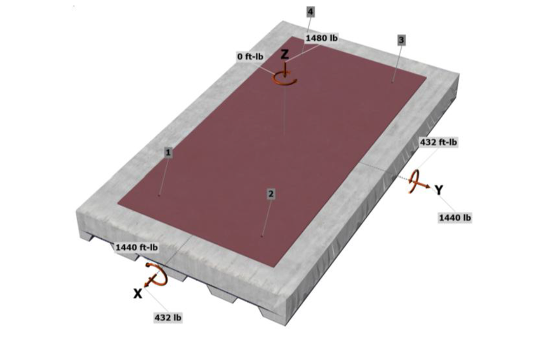
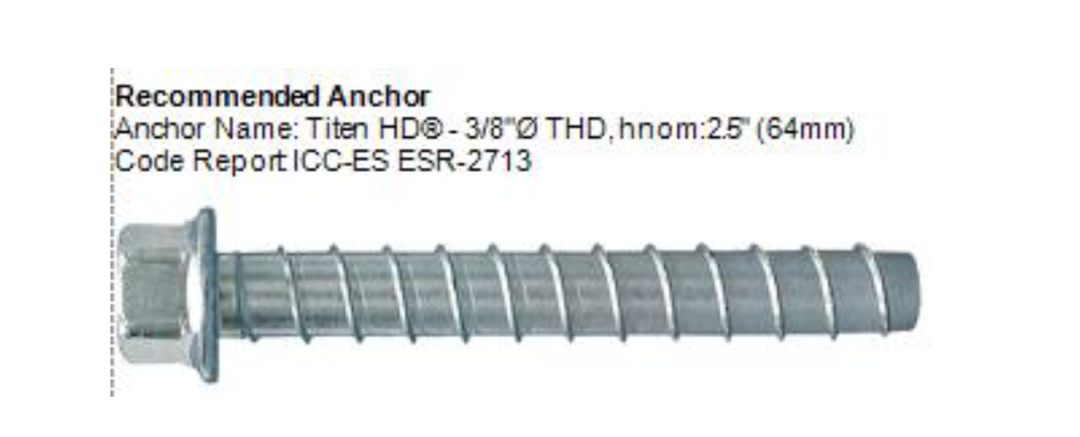
By inputting the base material information, loads, and geometry requirements, I found that (4) 3/8“–diameter Titen HD® heavy-duty screw anchors with 2.5“ nominal embedment depth placed near the corners of the unit (40” x 16“) are sufficient to resist the loads. Note that anchor spacing is typically dictated by the equipment manufacturer.
Since the equipment dimensions are not symmetrical, we do want to make sure the loads are applied in each direction to find the controlling load combination. This can be done using the project tree in the newest version of ADC.
ADC Project Tree:
Seismic Max in Y loads:
Seismic Max in X loads:
From the ADC Design Result:
The Titen HD is a great option for equipment anchorage as it is post installed and has great minimum edge distances and seismic approvals. You can find more information on the Titen HD and other post-installed anchor solutions at strongtie.com.
In summary, ASCE 7-22 introduced changes to the way we look at equipment anchorage by addressing behaviors of both the component and the support. Understanding these updates and using Simpson resources can help you design safer, stronger structures.
