The HDUE holdown is a steel connector system supplied with Strong-Drive® SDS Heavy-Duty Connector screws and engineered to provide high-capacity, efficient steel-to-wood post connections. An earlier blog post, “Unveiling the HDUE Holdown: Engineering Marvels and Rigorous Testing,” introduced the principal features of the HDUE product line and the engineering rationale underlying its development, including the use of angled screws to enhance load distribution within the connection.
This structural report extends the preceding discussion by presenting a technical assessment of HDUE screw installation direction based on physical testing and finite element analysis (FEA). The study evaluates the influence of screw orientation on the behavior of steel-to-wood holdown connections for three installation angles relative to the applied tensile load: 90° perpendicular, 45° downward away from the load, and 45° upward toward the load. The physical testing of the HDUE7 holdown was conducted using upward-oriented screws, and the resulting data were used to calibrate the finite element model. The calibrated model was subsequently applied to HDUE7 configurations incorporating both upward- and downward-oriented screws to assess how the single-fastener observations translate to full-connector behavior. Connection performance is evaluated in terms of deformation response, ultimate load capacity, and governing failure mode.
Mechanical Behavior of Screws
When tensile load is transferred from the wood post to the fasteners, the force demand in each screw is governed by its installation orientation. For a screw installed at an angle relative to the applied load, the resultant force may be resolved into two principal components: an axial component associated with withdrawal and a transverse component associated with shear. These components act simultaneously through the fastener and surrounding wood to resist the applied tensile demand.
For screws installed at an inclination relative to the applied load, the axial force component may additionally induce secondary bending in the fastener. This response occurs when the transferred load acts through an eccentric lever arm at the wood surface. The resulting bending moment is governed in both magnitude and direction by whether the screw is oriented toward or away from the applied load path.
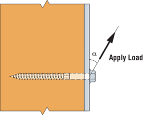 Figure 1: Screw Installed at an Angle to the Load
Screw Physical Testing and Finite Element Analysis
Physical testing and finite element analysis were conducted using the SDS25300 screw installed through a single-hole steel plate to evaluate deformation response, ultimate load capacity, and governing failure modes. The fastener test assemblies were constructed in accordance with ICC-ES AC233 Acceptance Criteria for Dowel-type Threaded Fasteners Used in Wood (Figure 2).

Figure 2: Physical Test Set–up
For screws installed at a 90° angle perpendicular to the applied load (Figure 3), force transfer is governed primarily by lateral shear in the screw shank and bearing at the wood interface. With increasing tensile demand, this shear-dominated mechanism promotes progressive fastener bending and may ultimately lead to screw failure. The screw bending also induces high stress in the surrounding wood, thereby increasing the likelihood of wood splitting (Figure 4).

Figure 3: Screw Installed at a 90° Perpendicular Angle

Figure 4: Failure Modes in Physical Testing and FEA for Screws Installed at 90° Perpendicular
For screws installed at a 45° angle downward relative to the applied load (Figure 5), the axial force component tends to draw the fastener toward the wood surface while simultaneously increasing bending demand in the shank near the loaded edge. This orientation produces concentrated tensile and flexural stresses in the near-surface region, thereby increasing the susceptibility to pullout and shear-related failure. Physical testing indicated fracture near the transition between the shank and threaded portion, where stress concentration was most pronounced (Figure 6).
Figure 5: Screw Installed at a 45° Downward Angle
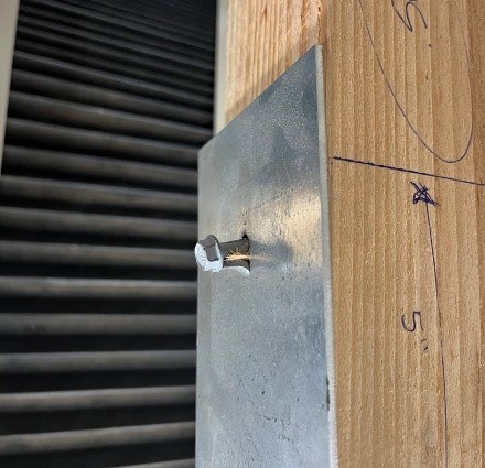
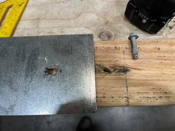

Figure 6: Failure Modes in FEA and Physical Testing for Screws Installed at 45° Downward
The results indicate that screws installed at a 45° angle upward relative to the applied load (Figure 7) transfer force deeper into the wood member and utilize both thread withdrawal resistance and shank shear resistance. This force-transfer mechanism distributes load over a larger effective wood volume and reduces stress concentration near the loaded edge. Consequently, bending demand near the screw head is reduced. In physical testing, the governing failure mode was screw bending accompanied by deformation of the positive-angle nailing (PAN) hole tab (Figure 8).
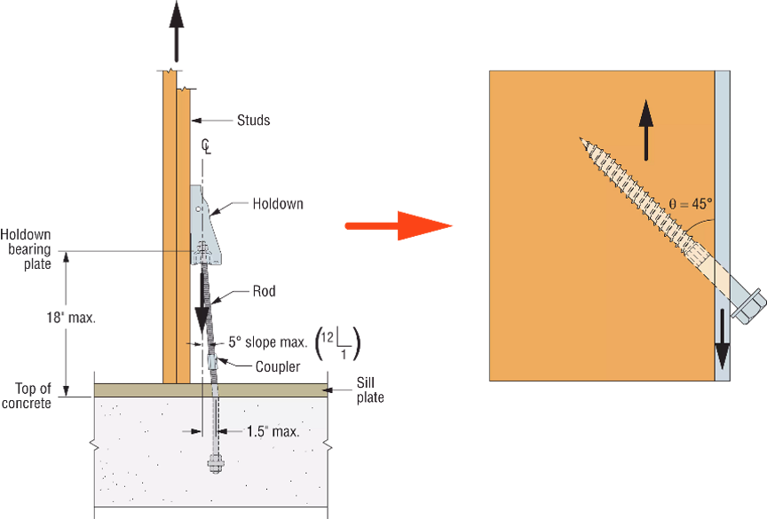
Figure 7: Screw Installed at a 45° Upward Angle

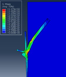

Figure 8: Failure Modes in FEA and Physical Testing for Screws Installed at 45° Upward
Table 1 summarizes the design values of SDS25300 screws for different installation angles relative to the load direction. The design values are based on the average ultimate test loads divided by a factor of 5.0. The results indicate that installation orientation has a significant effect on connection performance. The 45° upward configuration provides the highest capacity, while the perpendicular (90°) configuration represents an intermediate condition. In contrast, the 45° downward configuration shows a substantial reduction in capacity.
Table 1: Comparison of Test Results for Screws Installed at Different Angles
| Wood Fastener’s Installed Angle Relative to Applied Load |
Design Values (lb.) | % Capacity Compared with Lateral Design Values (Z) for Steel-to-Wood Shear (ICC-ES ESR-2236) |
| 90° Perpendicular | 420 | 100 |
| 45° Downward | 205 | 48 |
| 45° Upward | 595 | 142 |
Holdown Connector Physical Testing and Finite Element Analysis (FEA)
Physical testing was conducted on the HDUE7 holdown installed in a Douglas fir–larch post using a combination of 90° perpendicular screws and 45° upward-oriented screws. The tested configuration achieved a load capacity of 7,015 lb. On the basis of these results, the FEA model was calibrated to replicate the connection geometry and loading conditions employed in the test program. The FEA analytical predictions showed strong agreement with the physical testing. Concentrated high stress and deformation were observed in both the screws and the holdown body, indicating that the applied load was shared by both components.

Figure 9: Von Mises Stress and Screw Failure for Scenarios with Perpendicular Screws Combined with 45° Upward Screws
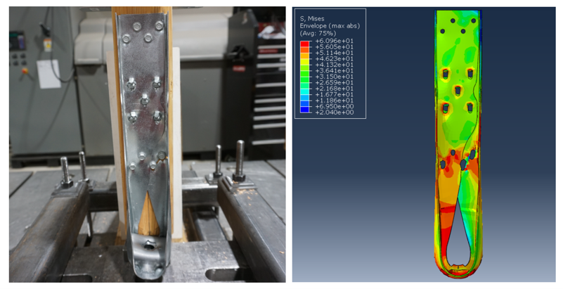 Figure 10: Failure Modes in Physical Testing and FEA
Using the same calibrated FEA model, the configuration with all screws installed at 90° perpendicular was evaluated. The predicted load capacity was 5,895 lb., approximately 16% lower than the configuration incorporating 45° upward-oriented screws. In this case, the screw governed the overall connection response.

Figure 11: Von Mises Stress and Screw Failure for Scenarios with 90° Perpendicular Screws
For the 45° downward-oriented screw configuration, the analysis predicted a load capacity of 4,180 lb., approximately 40% lower than the 45° upward-oriented configuration. The governing failure mode was bending of the inclined fastener, whereas the holdown body exhibited neither significant damage nor elevated stress.

Figure 12: Von Mises Stress and Screw Failure for Scenarios with Perpendicular Screws Combined with 45° Downward Screws
Table 2: Load Capacity of HDUE7-SDS3 Assemblies with Screws Installed at Different Angles
| HDUE7-SDS3 Assembly Configuration | Allowable Tension Loads (160) (lb.) | Deflection at Allowable Load (in.) |
| 90° Perpendicular | 5,895 | 0.043 |
| 45° Downward | 4,180 | 0.110 |
| 45° Upward | 7,015 | 0.154 |

Figure 13: Load-Displacement Curves of HDUE7-SDS3 Assemblies with Screws Installed at Different Angles
Conclusion
Screw installation angle exerts a substantial influence on the structural performance of the HDUE holdown. Both physical testing and finite element analysis demonstrate that screws installed at 45° upward relative to the applied load provide the highest ultimate capacity and the most favorable deformation response. On the basis of these findings, HDUE7 and higher-capacity HDUE holdown configurations incorporate PAN holes for combination of 45° upward-oriented screws and perpendicular screws to maximize load-transfer efficiency.