


This is the fourth Anchor Anatomy 101 blog post focusing on anchor systems. The goal of each post is to review anchor components, installation processes, and common applications to help you make informed anchor selection decisions based on your project’s unique requirements. The prior Anchor Anatomy 101 blog post focused on wedge type anchors. This blog post “drills down” into helical wall ties.
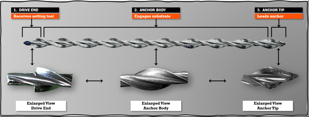
Stainless-steel helical wall ties were introduced in the late 20th century to anchor existing building façades to structural backup substrates and to stabilize existing multiwythe brick walls. They are a cost-effective and structurally sound solution that avoids the labor-intensive process of façade removal and replacement. Helical wall ties are designed as a post-installed mechanical anchor connection, sometimes referred to as a post-installed brick veneer tie. During installation, the outer fins of the tie undercut the masonry and/or grout, creating an expansion-free anchorage. In cases where the façade is detaching or otherwise showing instability, the helical wall tie re-establishes structural connection between the exterior veneer and the supporting substrate. The singular stainless-steel helical wall tie does not require epoxy, grout, or a bonding agent. Figure 1 shows the anchor anatomy of the Simpson Strong-Tie Heli-Tie™ helical wall tie (HT). The three key components pictured all contribute to its performance. Let’s take a closer look!
![Figure 2 — Heli-Tie™ Helical Wall Tie Installation Tool [HELITOOL37A]](http://seblog.strongtie.com/wp-content/uploads/2025/12/Figure-2-—-Heli-Tie™-Helical-Wall-Tie-Installation-Tool-HELITOOL37A-.png)
- Drive End: The first 1/2″ of the HT anchor body inserts into a proprietary installation setting tool (Figures 1 & 2). At this location, the helical fins are not present. The anchor body is a smooth solid section which allows it to rotate freely in the installation tool, HELITOOL37A. The installation tool and drive end work in tandem to drive the HT into the substrate and provide a 1/2″ countersink below the surface. This feature allows the drill hole to be patched and creates an inconspicuous repair preserving the façade’s appearance.
- Anchor Body: The main HT anchor body section follows the drive end. It consists of an inner solid round section circled by spiraling fins. Thanks to an advanced manufacturing process, the helical fins run continuously along the HT shaft length. The outside diameter of the HT is 3/8″ (9 mm). The large-diameter solid core gives the HT the ability to resist high torsion load and minimizes deflection due to “uncoiling” under load. The unique helical shape enables installations into various substrates with minimal substrate damage. The helical fins develop a “screw-like” threading effect that engage tightly into the substrate along the length of the HT. The result is an expansion-free connection which minimizes the potential for stress concentrations and provides both tension and compression load resistance.
- Anchor Tip: At the HT’s lead end, the helix tapers to a sharp tip. The tapering facilitates insertion into the predrilled substrate hole and helps penetrate any remnant drill hole debris.
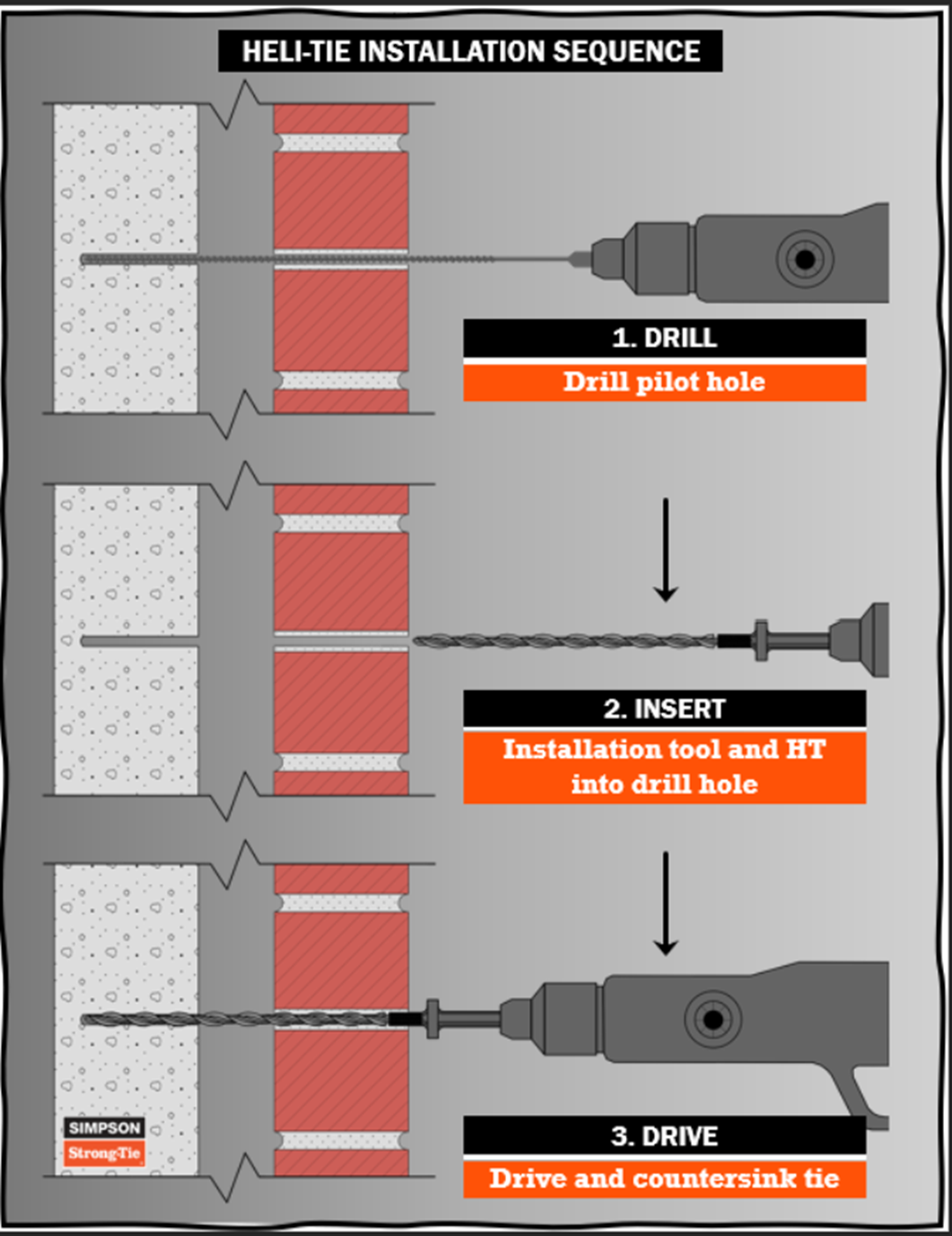
Installation Process (Figure 3)
- Drill: Installation starts with drilling a horizontal pilot hole through the façade and into the backup material to the required embedment depth plus an additional 1″. Next, a rotary hammer drill equipped with a carbide-tipped drill bit and set to rotation-only mode is used to drill the pilot hole. It is good practice to drill in rotation mode only when anchoring into soft masonry or hollow block to minimize cracking of the substrate. The drill bit diameter is either 7/32″ or 1/4″. Notably, the published values are greater when utilizing the smaller 7/32″ drill bit, but often contractors prefer the more commonly available 1/4″ drill bit. Due to the uncertain structural condition of the existing base material, a site-specific tension pull test is often used to verify substrate conditions, embedment depth, drill bit diameter, and structural performance. Contact your local Simpson Strong-Tie field engineer for guidance and support of Heli-Tie pull tests as desired. It should be noted that a specific Heli-Tie™ wall tie tension tester apparatus [HELITEST37A] is required for testing of the product.
- Insert: Next, place the HT installation tool’s SDS-plus® shank into the rotary hammer chuck. Place the HT drive end into the installation tool. Insert the rotary hammer with HT anchor tip into the pilot hole. (Note: SDS-plus is a trademark of the Robert Bosch Tool Corporation.)
- Drive: Set the rotary hammer to hammer mode, then drive the HT into the hole until the tip of the installation tool enters the exterior surface of the masonry and countersinks below the surface. Note that the drill mode is hammer mode during installation, not rotation only. Repoint the drill hole with proper matching material.
Heli-Tie™ Helical Wall Tie Applications
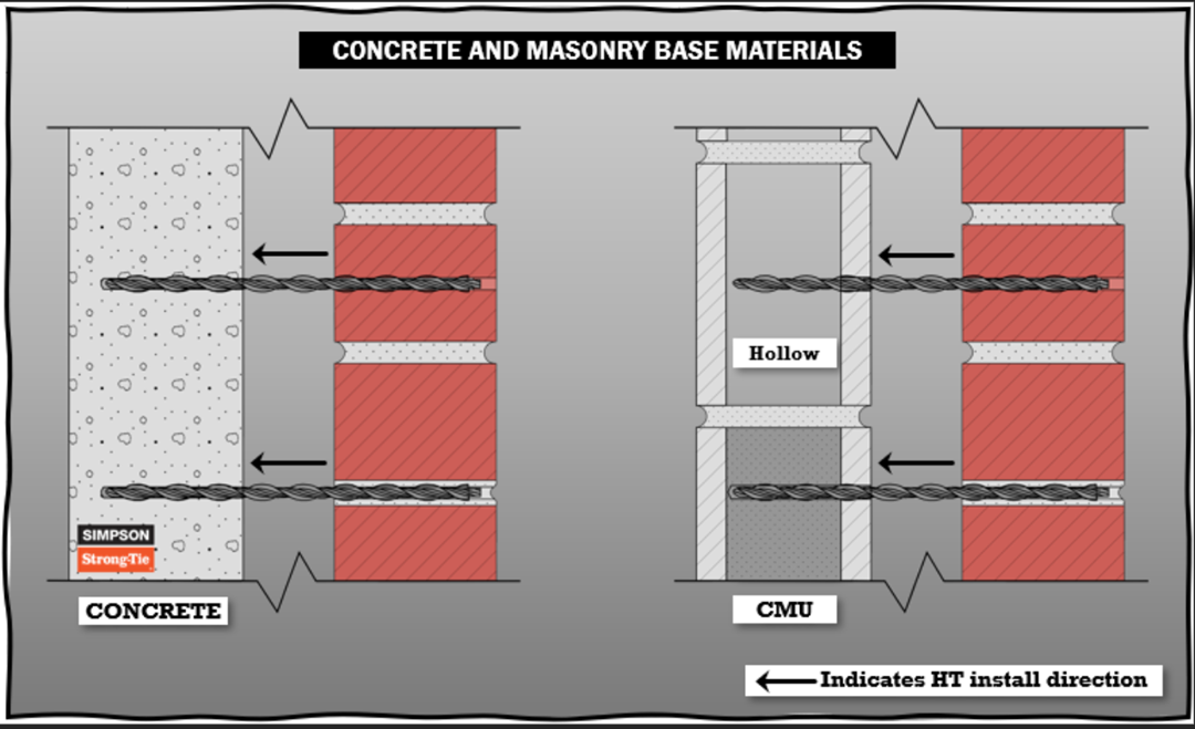
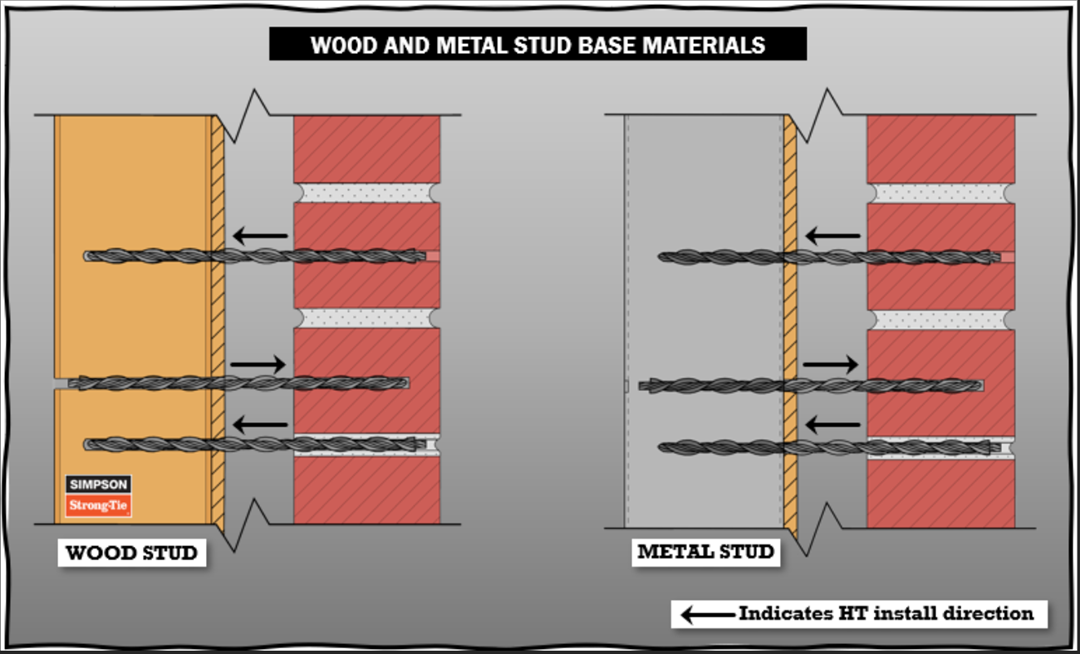
The most common HT application is anchoring an existing building façade back to a structural element (e.g., a wall, beam, column, or stud). The façade material is typically hollow or solid red brick, and often the structural element material is concrete. However, the HT’s expansion-free mechanical connection and installation method provide the opportunity for structural performance in a variety of façade and structural base materials. HTs can be installed in the mortar joint or the brick/CMU face and either from the inside of the structure or from outside the façade. Figures 4 and 5 display installation into concrete elements, grout-filled or hollow CMU block, wood studs, and light gauge metal (CFS) studs. Notably, for use connecting to wood studs or CFS studs, it’s easier to install the Heli-Tie from the interior of the structure, but installation from either side is allowed.
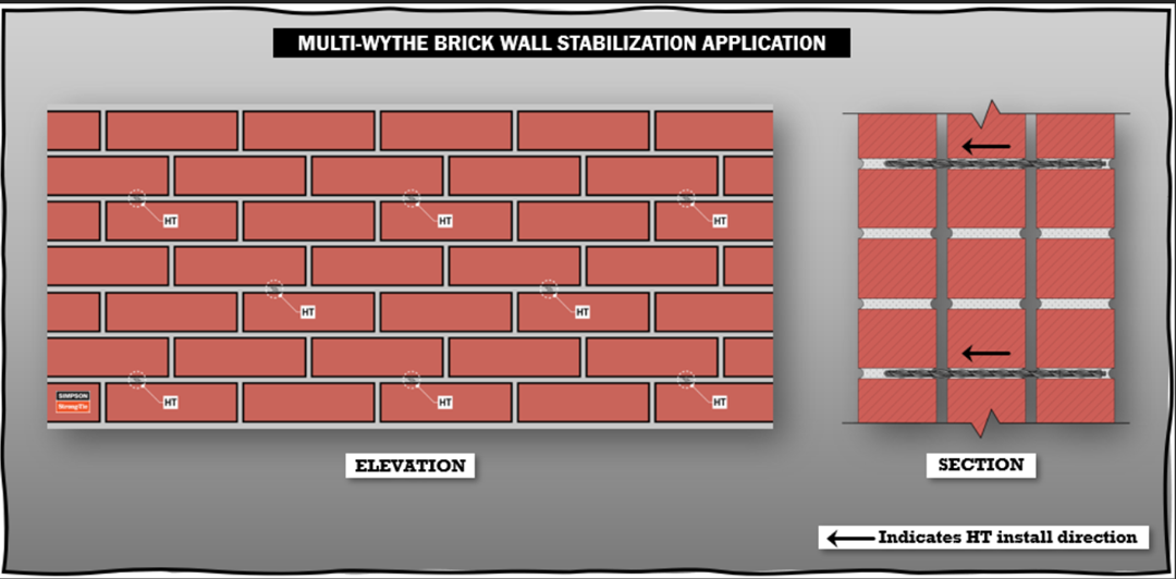
Another frequent HT application is stabilizing existing multiwythe brick walls (Figure 6). When the individual brick wythes are tied together, the wall acts as a larger assembly and gains stability. HTs are typically installed perpendicular to the wall in horizontal mortar joints with uniform spacing both vertically and horizontally along the entire wall, or sometimes only within designated sections to address specific wall conditions. This application is often used during seismic retrofits when a lateral–force–resisting system is installed at only the inside of the existing URM wall.
Other HT applications may include anchoring architectural quoins (masonry corner blocks), acting as a dowel to support new patching materials, reinforcing archways, connecting a new brick veneer to an existing brick wall, and pinning partially deteriorated veneers back to the structure. Specific conditions will necessarily govern the fitness for a given application.
Conclusion
Stainless-steel helical wall ties are a versatile, easy-to-install, cost-effective solution for anchoring veneers, stabilizing brick walls, and other repair or restoration applications. By understanding the Heli-Tie™ features, installation procedures, and structural applications, you can confidently specify it as appropriate on your next façade repair project. Note, refer to this SE blog for information on suggested HT design and spacing values.
Please stay tuned for the next Anchor Anatomy 101 blog post, featuring drop-in anchors. For questions about anchoring products or project-specific applications, please contact your local Simpson Strong-Tie field engineer.
