
[Simpson Strong-Tie note: Sam Hensen is the Simpson Strong-Tie Engineering Manager for the Southeast U.S. and the latest blogger for the Structural Engineering Blog. For more on Sam, see his bio here.]
Just as bending and shear checks performed on gravity loaded beams do not ensure that the beam will comply with required deflection limitations, adherence to allowable shears and aspect ratio limits on shearwalls does not mean the structure will comply with required drift limitations. Shearwalls that are too flexible may prevent the structure from meeting drift limitations even if the shearwall design has adequate strength.
Seismic
For seismic load applications, section 12.12.1 of ASCE7-10 states that the design story drift of the structure shall not exceed the allowable drift listed in table 12.12-1. For light-frame buildings, the maximum permitted drift is 2.5% of the story height. This limitation is put in place not merely for serviceability reasons, but is an inherent effect of current seismic design provisions that is required to be checked to ensure life safety.
Current seismic design provisions do not use the Maximum Considered Earthquake (MCE) response, but instead design procedures are in place to allow for a much smaller seismic force to be utilized based on the ability of the lateral resisting system to absorb and dampen the energy during the seismic event. This process requires the structure to deflect under each cycle of loading, but not deflect enough for a collapse to occur, so this method relies heavily on ductility inherent in the chosen lateral resisting system. More ductile systems can undergo larger deflections when loaded and the benefit is a lower seismic design force. A simple steel frame and yield curve is shown below to further clarify the definition of ductility.
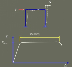
An increase in the lateral resisting system ductility means a lessened seismic design force for the structure (see graph below). On a separate note, the reliance on ductility for seismic design is one reason seismic detailing and limitations must be followed even when wind controls the design. Take a look at Paul’s previous blog post, Ignore Seismic Requirements When Wind Controls?
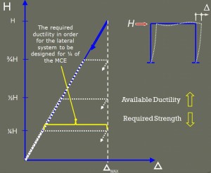
Okay, back to our original discussion. Since the amount of deflection the lateral system will undergo is not just a serviceability issue, the required deflection check is even more critical than for gravity loaded systems due to P-Delta effects. Although deflection checks including P-Delta effects are included in most structural analysis software, this design check is often omitted in structures analyzed by hand.
Wind
Traditionally, for high wind design, we used the actual pressures the building is expected to experience. The building was expected to perform well not just for life safety, but also to sustain minimal cosmetic damage and protect the contents and belongings. Currently ASCE7-10 requires all building envelope openings be protected from flying debris in wind-borne debris regions, allowing the designer to use a much smaller internal pressure (3x less than when not protecting the openings.) This measure was put in place in ASCE7-05 and was a result of losses realized when the building envelope is penetrated during the wind event and significant damage occurring from water intrusion.
One of the most popular methods used to protect openings is to use impact-resistant glazing systems. There are racking limitations for this type of opening protection in order for them to work properly and maintain their structural integrity. In my opinion, this issue is addressed in section 4.1.3 of the Special Design Provisions for Wind and Seismic (SDPWS). It states, “Deformation of connections within and between structural elements shall be considered in design such that the deformation of each element and connection comprising the lateral force-resisting system is compatible with the deformations of the other lateral force-resisting elements and connections and with the overall system.”
The only way for a design to be in conformance with these wind or seismic requirements is for the designer to check building drift and ensure that the components within the lateral force-resisting system are all compatible and do not exceed the allowable drift. If they are not compatible or have excessive drift, then additional considerations must be made, just as we would increase the depth of a beam to comply with serviceability deflection requirements.
What are your thoughts? Let us know by posting a Comment.
– Sam
What are your thoughts? Visit the blog and leave a comment!




Based on my review of many designs for residential construction by different engineers, I have found that drift calculations are not being performed. I think a great article for you to write would be a practical example on how to perform the calculation.
Most of the values used to check deflection requirements are educated guesses at best checking a building for deflection is a moot point. You’ll never know where chord splices occur and I doubt that the contractor would follow a detail for one if it was provided.
How do I calculate the interstory drift ratio for wind for a steel frame with CBFs
You would typically use analysis software, such as SAP2000, ETABs, Risa, STAAD, etc, to determine the building story deflections for steel frames. It can be done by hand for simpler building geometries, but it can be quite time consuming.
Once you have overall deflections, calculating the story drifts is simply taking the story deflection and subtracting the deflection of the story below. Although some analysis software will output story drift directly.
I do not see a recommendation for allowable wind drift
Calculation of drift is very important on limited lot location. And for residentials, it is very infinitismal at the adjacent building. Base on the formula drift (max.) = 4% x ht.and ht usually and normally only 3 mtrs per storey.