


Unreinforced masonry (URM) buildings in moderate- to high-seismic areas can be a disaster in waiting. These types of structures have very little of the ductility required of structures to prevent loss of life or business disruption in a seismic event. (Consult our Structural Engineering Blog post “Building Drift – Do You Check It?” for a discussion on ductility.) Many of these buildings are in densely populated areas, have historical meaning, provide important living or business spaces, and can be costly to retrofit. In this blog, Simpson Strong-Tie engineers discuss tools available for engineers to assess these buildings and design the retrofits needed to mitigate a potential loss of life and increase seismic resiliency.
Author: Sam Hensen
I graduated from USC (University of Southern California), and am a licensed Civil Engineer in California and 11 other states including Texas, Florida and South Carolina. Currently, I'm the engineering manager for Simpson Strong-Tie in the Southeastern U.S., and consider myself fortunate to work with a very talented group of engineers and technical staff that provide support for Simpson Strong-Tie on all technical-related issues in the Southeastern region.
The Southeast has a mix of all the design challenges Mother Nature can throw at us. From high seismic areas, like the New Madrid and Charleston faults, to hurricane-prone regions, like the Gulf and Eastern coast, to tornado-prone areas, like the South and Midwestern states. This wide array of external structural design challenges provides Simpson Strong-Tie with many opportunities to offer technical support to the construction industry – whether it is seismic or wind related – and demands engineers in this area to be proficient in all of them.
I began my career with Simpson Strong-Tie in 2000 at our Southern California branch and was privileged to work with many incredible engineers that Simpson Strong-Tie employs there. I moved to Texas in 2005 to manage the engineering department in the Southeast and began to hone my skills on wind related design challenges. Having an understanding of both seismic and wind design challenges makes it much easier to handle the technical demands in the Southeast.

Open Front Structure Wind Pressure Design
We received a request from Martin H., one of our blog readers, to discuss the method for determining roof wind pressures on an open front agricultural building. The inquiry was regarding clarification on analyzing the roof pressure when a combined external and interior pressure exists and whether these are additive.
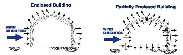
As can be seen in the above illustrations, the net design pressure on the roof is the sum of the uplift on the exterior surface and the uplift on the interior surface from any internal pressure. ASCE 7 provides a method for determining this pressure. Specifically, ASCE 7-22 will be used for the remainder of this post. Assuming the three remaining sides of the open front structure are walls without openings, the building will be classified as partially enclosed by the definitions of Section 26.2.
ASCE 7-22 provides for two methods for determining the Main Wind Force Resisting System (MWFRS) wind loads for partially enclosed buildings, the Directional Procedure in Chapter 27, and the Envelope Procedure in Chapter 28.
When using the Directional Procedure, the net wind load is calculated using the following equation:
P = qGCp – qi(GCpi)
When using the Envelope Procedure, the net wind load is calculated using the following equation:
P = qh[(GCpf) – (GCpi)]
In each of these equations, the first portion determines the pressure on the exterior surface, and the second portion determines the pressure on the interior surface. So the variable for calculating the internal pressure is the internal pressure coefficient GCpi.
The internal pressure coefficient is provided in Table 26.11-1 based on three different categories of building enclosure.
|
Enclosure Classification |
(GCpi) |
| Open Buildings |
0.00 |
| Partially Enclosed Buildings |
+0.55 -0.55 |
| Enclosed Buildings |
+0.18 -0.18 |
Table 26.11-1
In the case of an open front structure, it is assumed that the partially enclosed internal pressure coefficient must be used. This coefficient is 3x greater than when the building envelope is classified as enclosed. Use of this higher coefficient in the design will account for the interior pressure on the underside of the roof combined with the exterior pressure.
MWFRS versus C&C
Another somewhat related question: to what level loads should the roof anchorage forces be calculated, MWFRS or C&C (Component and Cladding)? I have often been asked this question, and wrote a Technical Note published by CFSEI (Cold-Formed Steel Engineers Institute) in July 2009.
What are your thoughts?
– Sam
What are your thoughts? Visit the blog and leave a comment!

Building Drift – Do You Check It?

[Simpson Strong-Tie note: Sam Hensen is the Simpson Strong-Tie Engineering Manager for the Southeast U.S. and the latest blogger for the Structural Engineering Blog. For more on Sam, see his bio here.]
Just as bending and shear checks performed on gravity loaded beams do not ensure that the beam will comply with required deflection limitations, adherence to allowable shears and aspect ratio limits on shearwalls does not mean the structure will comply with required drift limitations. Shearwalls that are too flexible may prevent the structure from meeting drift limitations even if the shearwall design has adequate strength.
Seismic
For seismic load applications, section 12.12.1 of ASCE 7-22 states that the design story drift of the structure shall not exceed the allowable drift listed in table 12.12-1. For light-frame buildings, the maximum permitted drift is 2.5% of the story height. This limitation is put in place not merely for serviceability reasons, but is an inherent effect of current seismic design provisions that is required to be checked to ensure life safety.
Preventing Roof Tiles from Becoming Wind-Borne Debris in High Wind Regions
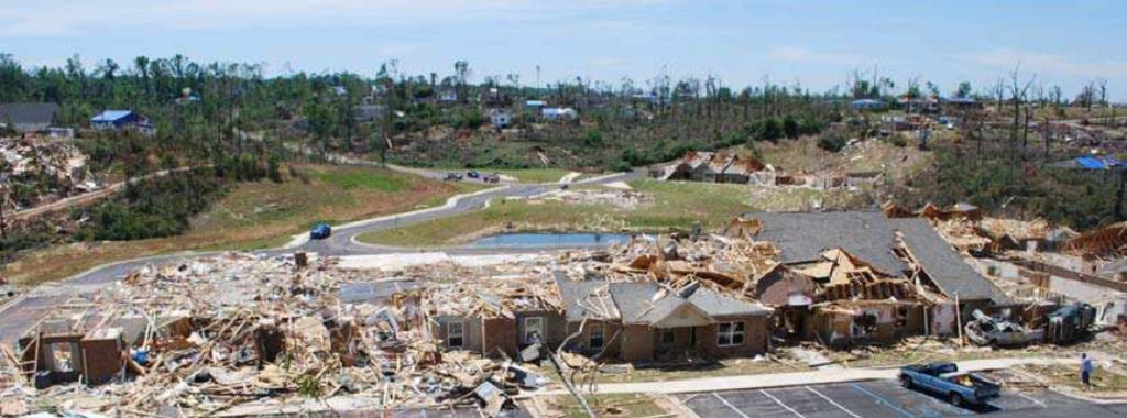
I tend to think of designers as dealing with either wind or seismic design, yet the Southeast region contains everything that Mother Nature can throw at a building. This includes high seismic areas along the New Madrid and Charleston faults, hurricanes along the Gulf and Eastern coast, and tornado prone areas throughout the South and Midwest. Sam participated in the investigation and was a co-author of the Damage Study and Future Direction for Structural Design Following the Tuscaloosa Tornado of 2011, which gives him some very recent experience with tornado damage. This week, Sam will be discussing a topic not often thought about by structural engineers – the importance of proper roof tile attachments. Here is Sam’s post:
According to recent studies by the Insurance Institute for Business Home and Safety (IBHS), roof coverings are a major problem area in wind-related events and account for 95% plus of home claims after the event.
Preventing roof tiles from becoming wind-borne debris in high wind regions is essential for several reasons, and may also have an effect on insurance premiums. In this post, I’d like to discuss two reasons that roof tiles can pose a significant threat to life safety: