In last week’s post I made a reference to California’s golden sunshine. Californians may have to deal with wildfires, earthquakes, and wearing sunscreen year round, but we generally don’t have high wind to worry about. In a previous blog post, Roof Deck Design Considerations for High Wind Events, I discussed some of the general challenges in designing for wind uplift. This week, I wanted to get a little more specific and discuss the standards applicable to steel roof deck attachments.
Historically, procedures for design of structural connections that utilize fasteners recognize the importance of combined loading effects on structural performance. Whether bolts or screws are the connector choice, the metallic structure of steel alloys includes transverse slip planes of relatively low resistance. This results in yield criteria (function that defines the onset of yielding or fracture) that are often limited by load-deformation performance along transverse planes.
Under the action of uniaxial tension or compression, internal shear stresses develop even in the absence of externally applied shear. A logical (or maybe not so logical) conclusion is that when considering combined loading, the application of axial tension or compression will take-up a portion of the shear capacity that was originally available to resist externally applied shear forces. Case made regarding the importance of combined loading effects.


So what defines the Standard of Practice for combined loading in connection design? The answer depends on the specific material type.
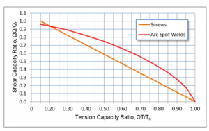
For cold-formed steel, refer to the North American Specification for Design of Cold Formed Steel Structural Members S100-07 by the American Iron and Steel Institute (AISI). The International Building Code references ANSI/SDI RD1.0 and the Steel Deck Institute (SDI) – Diaphragm Design Manual (DDM) for design of steel deck diaphragms. Specifically, section 4.10 of the SDI DDM 3rd edition presents equations for design of deck connections under the combined effect of tension and shear. These equations were developed from single fastener testing consisting of the application of concentric tension loads over a range of angles (0° to 90°). Equations were derived from best fit curves of the test data as a function of fastener type. Of the fastener types available, arc spot welds (best known as puddle welds), screws and powder actuated pins (PAP) were considered.
Several points are worth noting regarding the SDI DDM equations:
- The interaction relationship is linear for screws and exponential for welds. A side by side comparison of the two equations (see figure) indicates better combined capacity results from a welded connection, in other words, for a given tension ratio (ΩT/Tn), higher shear ratios (ΩQ/Qf) are permitted for welds than for screws. The equations were determined from testing under “ideal” laboratory conditions which are much more difficult to replicate in the field with welds than with screws. The obvious question: Should the interaction relationship account for installation quality? For allowable stress design, safety factors are usually included to account for issues such as installation quality. The tension safety factors in SDI DDM are 2.5 for welds and 3.0 for screws. The safety factor for shear is based on load type and is the same for both welds and screws. Based on current code defined safety factor values, the current design process doesn’t seem to account for installation quality.
- The terms Q and Qf in the SDI DDM interaction equations define the shear service load demand and nominal shear capacity of support connections, respectively. To design an adequate deck fastening pattern (with capacity greater than or equal to service shear load demand Q), load capacity contributions from both support fasteners (Qf) and side lap fasteners (Qs) must be considered. The available shear capacity of support fasteners (Qf) should be reduced under the application of uplift loads as a result of load interaction. The load capacity provided by sidelap connections is unaffected by load interaction. Values of Qf and Qs for screws must be determined from equations defined in SDI DDM, section 4.5.
- The terms T and Tn in the interaction equations define the tension service load demand and nominal tension capacity of support connections. Tension service load demand must be determined by multiplying component and cladding roof uplift pressures by the tributary area of support fasteners. Nominal tension capacity values for screws must be the minimum from tension pullout and pullover determined by either testing or equations presented in the S100-07 AISI specification, section E4.4. Similarly, the tension capacity of arc spot welds is defined in section E2.2 of the S100-07 specification.
Refer to the Steel Deck Institute website for information related to the Diaphragm Design Manual.
Standard ANSI/SDI RD1.0 can be downloaded from SDI Publications.

– Paul
What are your thoughts? Visit the blog and leave a comment!


