

Launched in January 2013, the Simpson Strong-Tie® Strong Frame® special moment frame (SMF) has been successfully used on many projects around the country. We’ve explored several aspects of the frame in previous blog posts, including beam bracing requirements, soft story retrofits, and the San Francisco retrofit ordinance. If you have specified the Strong Frame SMF on your project, here are a few helpful items to review during your structural observations at installation.
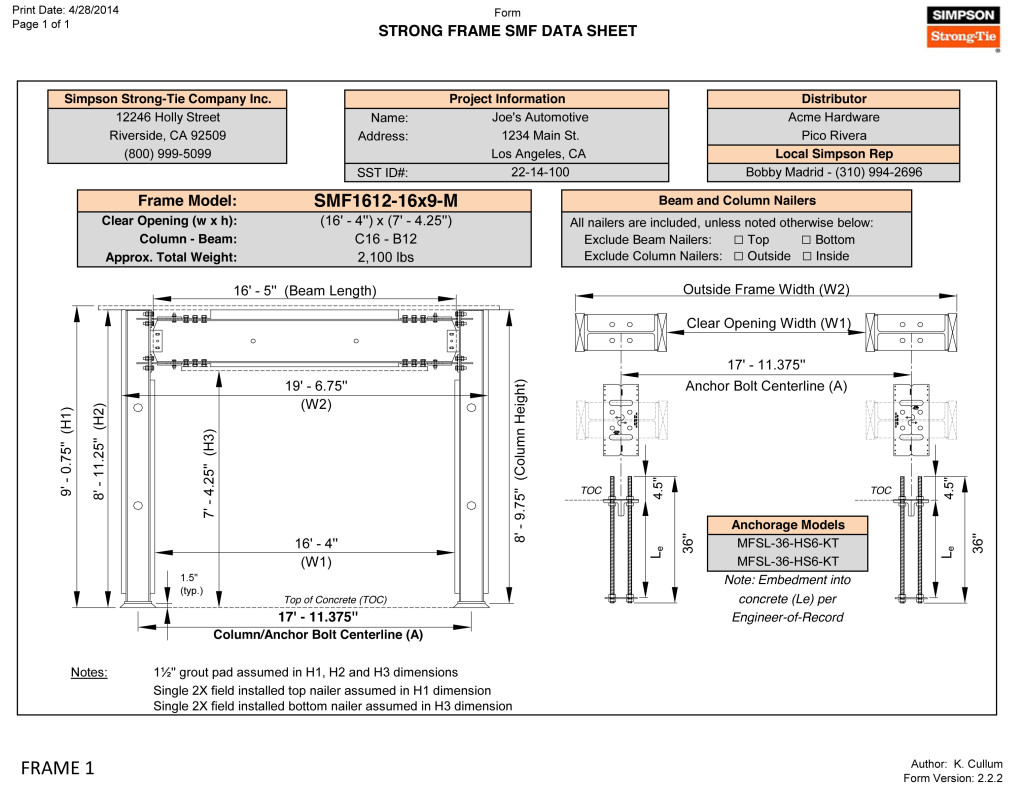
When the special moment frame is ordered, Simpson Strong-Tie sends the contractor a frame verification sheet to verify the dimensions (Figure 1). It is not uncommon for minor adjustments to be made to accommodate specific field conditions. We recommend the framer follow up with the Designer to ensure the needed modifications do not alter the design of the frame based on deflection or strength stand point limitation(s). Once we receive the signed verification, we begin fabricating the frame. The accompanying concrete anchors are usually shipped before the frame so they can be placed ahead of time.
 It all starts with the concrete! The majority of misinstallation issues involve anchorage placement. Anchors not placed correctly can alter the frame that’s already been ordered, affecting lead times or requiring retrofit to properly transfer the frame forces into the concrete. Contact your local Simpson Strong-Tie sales rep to help with any questions.
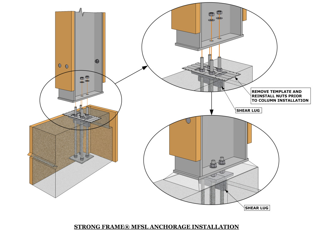
Placement of the Moment Frame Shear Lug (MFSL) is critical to ensure proper transfer of shear forces into the foundation. If you are visiting the jobsite prior to concrete placement, take a look at the orientation of the MFSL. The MFSL contains back-to-back structural angles placed at the top of concrete to transfer the shear component of the Strong Frame SMF forces into the concrete. Figure 2 shows the proper placement of the MFSL and template in relationship to the direction of the column.
The template has a similar appearance to the shape and size of the column base plate, which sometimes leads to the tendency to orient the template 90 degrees from its proper installation, as shown in Figure 3. The template has two half circles at the center of the anchor bolts for proper measurement (center-to-center of columns) by the contractor, as shown in Figure 4.
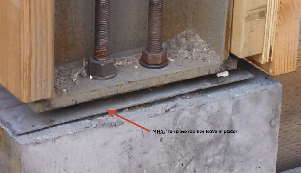

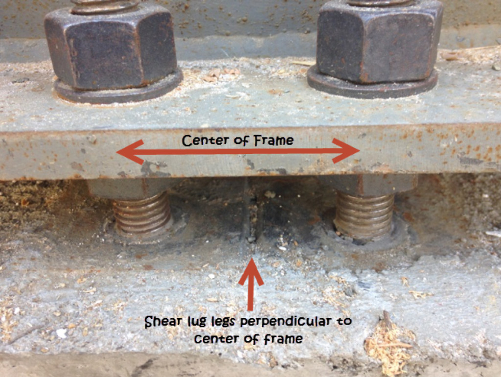
The templates are temporary and intended to be removed prior to frame installation (unlike the case in Figure 3). So placement of the shear lugs is more critical to verify than the direction of the template, since the contractor may remove the template and reinstall it in an alternate orientation. The vertical legs of the two structural angles should intersect the column’s weak axis (perpendicular to center of frame) as shown in Figure 5, and should not be placed parallel to the strong axis.
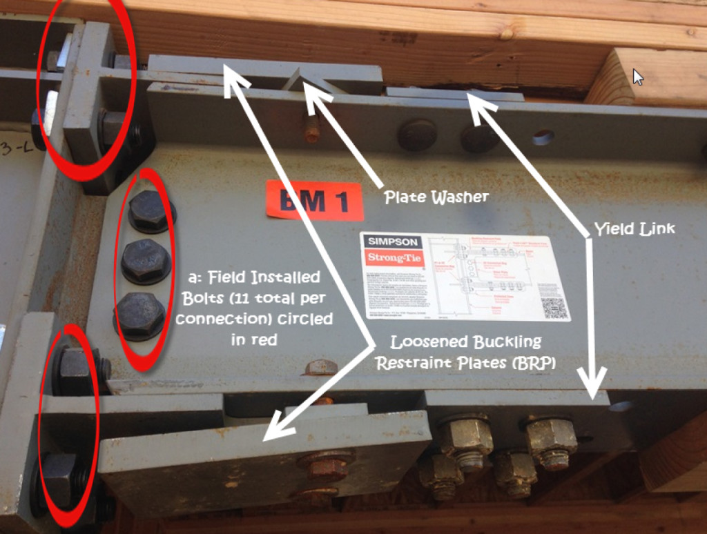
According to ASTM A325, installation requires 11 bolts snug tight at each beam-column connection (labeled “a” in Figure 6), and the column needs to be attached to the four anchor bolts into the base of each column. Many components of the Strong Frame SMF are factory-installed, including the Yield-LinkTM structural fuses, Buckling Restraint Plates (BRP), and nailers. The Yield-Link fuses and BRP should not be disassembled. Figure 6 illustrates an instance where the BRP was loosened during erection. The BRP prevents the Yield-Link fuses from buckling when the frame is subjected to compression forces. Contact Simpson Strong-Tie if you encounter this in the field.
The wood nailers may be replaced in kind. It is important to note that attachment of the nailers may not utilize all available bolt holes on the column and beam. Various holes are left unused for flexibility with installation of utilities and electrical wiring.
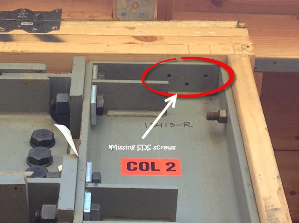
Lastly, often overlooked at installation are the required SDS screws through the column cap plate into the framing above (Figure 7). The SDS screws are included with the installation kit. They are required for bracing of the column on both faces of the column.
How is the Strong Frame special moment frame working for you? Please let us know in the comments!

1 thought on “Special Moment Frame Installation: What Structural Engineers Should Watch For”
Comments are closed.