A previous blog post described how Simpson Strong-Tie tests and loadrates connectors used with cold-formed steel structural members per acceptance criteria ICC-ES AC261.
This week, I would like to describe how we test and determine engineering design values for RCKW, Rigid Connector Kneewall, in a CFS wall assembly and how the data can help designers perform engineering calculations accurately and efficiently.
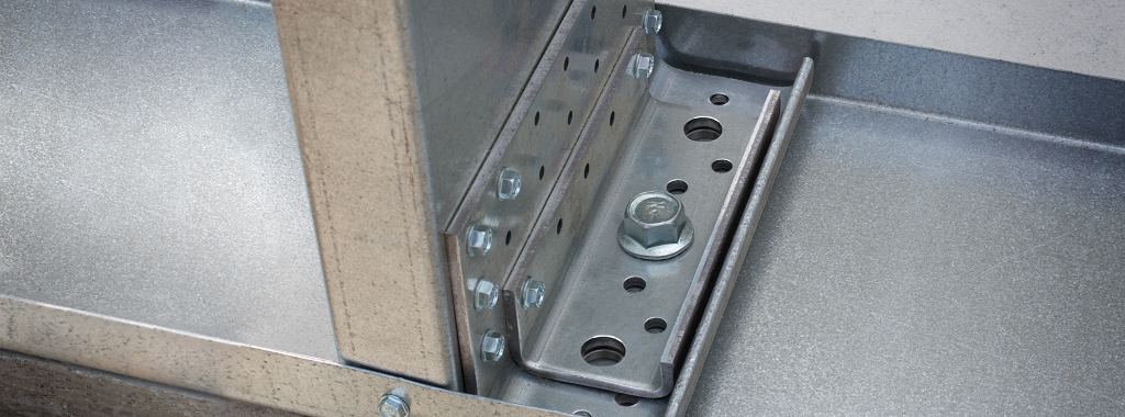
The RCKW was developed to provide optimal rotational resistance at the base of exterior kneewalls, parapets, handrail and guardrail systems as well as interior partial-height walls.
RCKW connectors were tested in CFS wall assemblies for 33 mil, 43 mil, and 54 mil steel thicknesses and in stud members with depths from 3½ to 8 inches. RCKW connectors with stiffeners, RCKWS, were also tested in CFS wall assemblies for 43 mil, 54 mil, and 68 mil stud thicknesses.
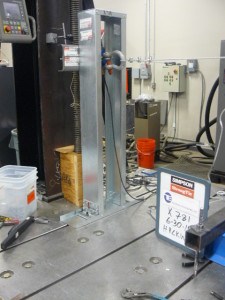
The wall assembly is built using CFS stud framing, bottom and top tracks simulating the kneewall application in the field. The RCKW connectors are fastened to a stud using self-drilling screws and an anchor to the test bed foundation. The horizontal load (P) is applied to the CFS wall assembly at a height (hwall) of 38 inches. The instruments are also placed at the same height as the applied load to measure wall deflection. The load and deflection data are recorded concurrently until the wall assembly fails.
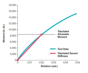
The allowable moment, MASD, is determined by multiplying PASD, the allowable horizontal load, by hwall, wall height (MASD = PASD * hwall).
PASD is calculated from peak load or nominal load, PNominal, divided by Ω, a safety factor per AISI 100 Chapter F. The blog post on Cold-Formed Steel Connectors discusses safety factors for CFS testing.
Similarly, the allowable rotational angle, θASD, is also determined by wall deflection at allowable load, ∆ASD, divided by hwall (θASD = ∆ASD / hwall).
So the assembly rotational stiffness, β, is calculated by MASD, divided by θASD (β = MASD / θASD).
The typical test performance curve for moment versus rotational angle is concave down and increasing as shown in the blue color curve. As a result, the rotational stiffness for RCKW is established by the secant stiffness, which is a red color straight line from zero to the allowable moment as shown below.
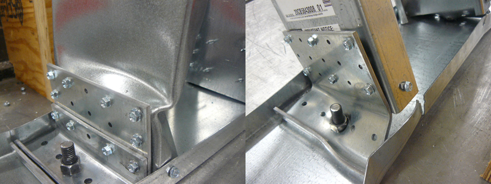
The rotational stiffness captures connector deflection, stud deflection and fastener slip in various stud thicknesses. Whereas when the connectors are tested in a steel jig fixture, the rotational stiffness includes connector deflection only and not the fastener and stud deflection behaviors. The photos below are examples of member failures which include stud buckling, bottom track tearing, and screws tilting and bearing. These failure modes are reflected in our tabulated loads because of our assembly testing.
Designers might wonder why the rotational stiffness is so important and how significant it is in Engineering Design. The IBC 2012 Building Code, Section 1604.3 indicates that structural systems and members shall be designed to have adequate stiffness to limit deflections and lateral drift. Table 1604.3 also provides deflection limits for various construction applications to which the Engineer must adhere.
For example, one of many common applications in CFS construction is the exterior kneewall system below a large window opening subject to the lateral pressure load. This kneewall system must not only be designed to provide moment strength to avoid the hinging failure at the base, but it must also be designed for deflection limits to prevent excess lateral drift that could result in cracking from various types of finish materials.
Since we performed comprehensive testing of full assemblies, engineers do not need to add stud deflection and fastener slip to the calculation. This saves time and eliminates guesswork with their specifications in a common 38 inch kneewall height.
Furthermore, we analyzed the test data to determine connector rotational stiffness, βc, which includes connector deflection, fastener slips, but not the stud deflection. Connector rotational stiffness allows engineers to perform deflection calculations for assemblies of any height. Design examples are available in the RCKW Kneewall Connectors flier.
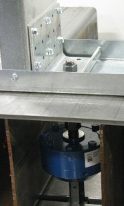
Simpson Strong-Tie recognizes the complexity of performing hand calculations to accurately determine the anchorage reactions for the RCKW connectors. This post on Statics and Testing described how we established loads for our CFS SJC products through testing. We have also provided anchor reaction loads for connectors at allowable moments so engineers could skip this step in the calculations. We measure the anchor reactions by connecting the calibrated blue load cells with the threaded rod that anchors the RCKW connector. The load cell measures the tension forces in the rod directly.
Connector strength and stiffness are critical for RCKW products where calculation or interpolation cannot capture the true performance accuracy the same way that testing would. For this reason, we have tabulated values for various stud member depths and thicknesses. Like Paul, I am amazed at the number of tests that go into this product. Ultimately, we can provide complete Engineer Design values that our specifiers can trust in determining adequate strength and stiffness to meet the code requirement.



I like the use of a load cell on the anchor side.