Jhalak Vasavada is currently a Research & Development Engineer for Simpson Strong-Tie. She has a bachelor’s degree in civil engineering from Maharaja Sayajirao (M.S.) University of Baroda, Gujarat, India, and a master’s degree in structural engineering from Illinois Institute of Technology, Chicago, IL. After graduation, she worked for an environmental consulting firm called TriHydro Corporation and as a structural engineer with Sargent & Lundy, LLC, based in Chicago, IL. She worked on the design of power plant structures such as chimney foundations, boiler building and turbine building steel design and design of flue gas ductwork. She is a registered Professional Engineer in the State of Michigan.
At Simpson Strong-Tie, we strive to make an engineer’s life easier by developing products that help with design efficiency. Our products are designed and tested to the highest standards, and that gives structural engineers the confidence that they’re using the best product for their application.
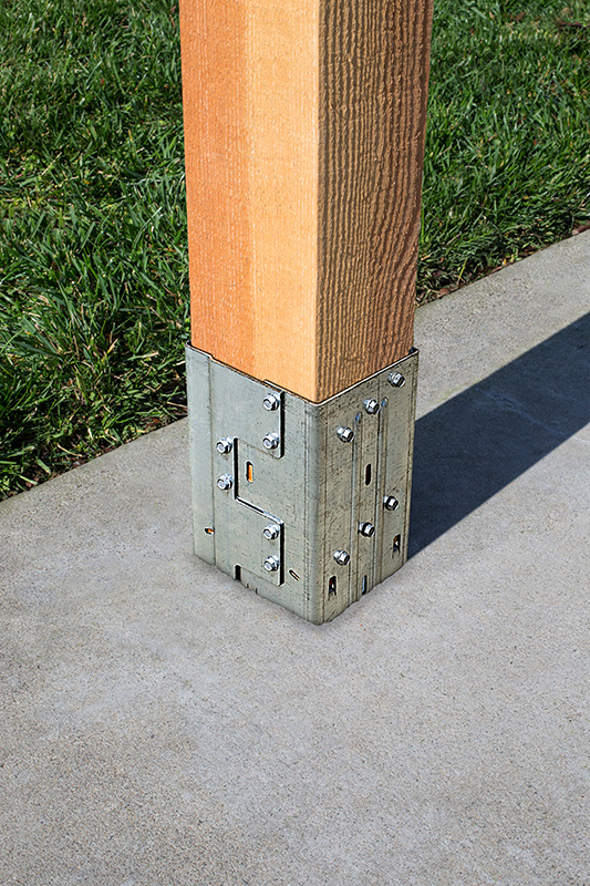
Having worked in the design industry for almost a decade, I can attest that having a catalog where you can select a product that solves an engineer’s design dilemma can be a huge time- and money-saving tool. Design engineers are always trying to create efficient designs, although cost and schedule are always constraints. Moment connections can be very efficient — provided they are designed and detailed correctly. With that in mind, we developed a moment post base connector that can resist moment in addition to download, uplift and lateral loads. In this post, I would like to talk about moment-resisting/fixed connections for post bases and also talk about the product design process.
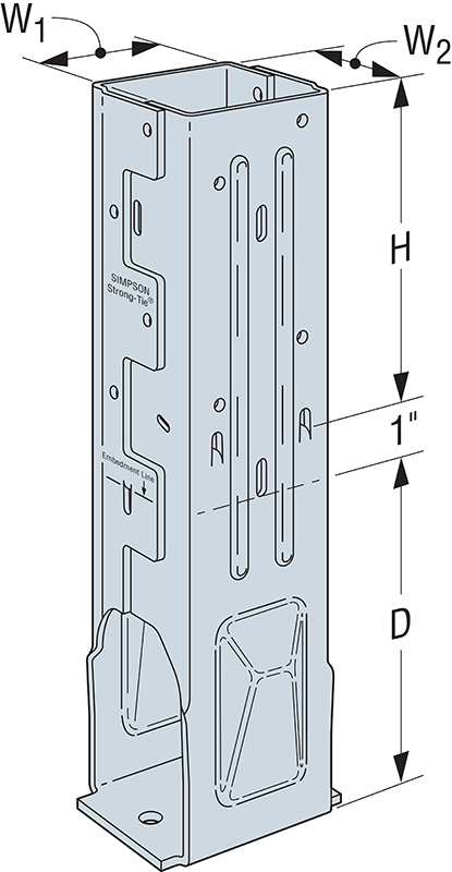
Lateral forces from wind and seismic loads on a structure are typically resisted by a lateral-force-resisting system. There are three main systems used for ordinary rectangular structures: (a) braced frames, (b) moment frames and (c) shearwalls. Moment frames resist lateral forces through bending in the frame members. Moment frames allow for open frames by eliminating the need for vertical bracing or knee bracing. Moment resistance or fixity at the column base is achieved by providing translational and rotational resistance. The new patent-pending Simpson Strong-Tie® MPBZ moment post base is specifically designed to provide moment resistance for columns and posts. An innovative overlapping sleeve design encapsulates the post, helping to resist rotation at its base.
The allowable loads we publish have what I call “triple backup.” This backup consists of Finite Element Analysis (FEA), code-compliant calculations and test data. Here are descriptions of what I mean by that.
Finite Element Analysis Confirmation
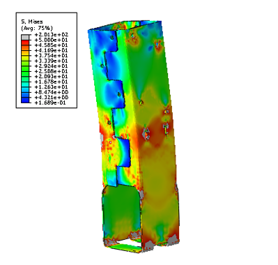
Once a preliminary design for the product is developed, FEA is performed to confirm that the product behaves as we expect it to in different load conditions. Several iterations are run to come up with the most efficient design.
Code-Compliance Calculations
Load calculations are prepared in accordance with the latest industry standards. The connector limit states are calculated for the wood-post-to-MPBZ connection and for MPBZ anchorage in concrete. Steel tensile strength is determined in accordance with ICC-ES AC398 and AISI S100-07. Wood connection strength is determined in accordance with ICC-ES AC398 and AC13. Fastener design is analyzed as per NDS. SDS screw values are analyzed using known allowable values per code report ESR-2236. The available moment capacity of the post base fastened to the wood member is calculated in accordance with the applicable bearing capacity of the post and lateral design strength of the fasteners per the NDS or ESR values. Concrete anchorage pull-out strength is determined in accordance with AC398.
Test Data Verification
The moment post base is tested for anchorage in both cracked and uncracked concrete in accordance with ICC-ES AC398.
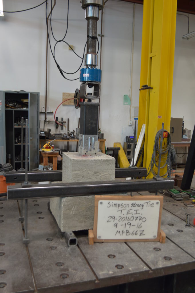
The moment post base assembly is tested for connection strength in accordance with ICC-ES AC13.
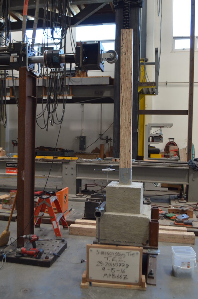
The assembly (post and MPBZ) is tested for various loading conditions: download, uplift and lateral load in both orthographic directions and moment. Applicable factor(s) of safety are applied, and the controlling load for each load condition is published in the Simpson Strong-Tie Wood Construction Connectors Catalog.
Now let’s take a look at a sign post base design example to see how the MPBZ data can be used.
Design Example:
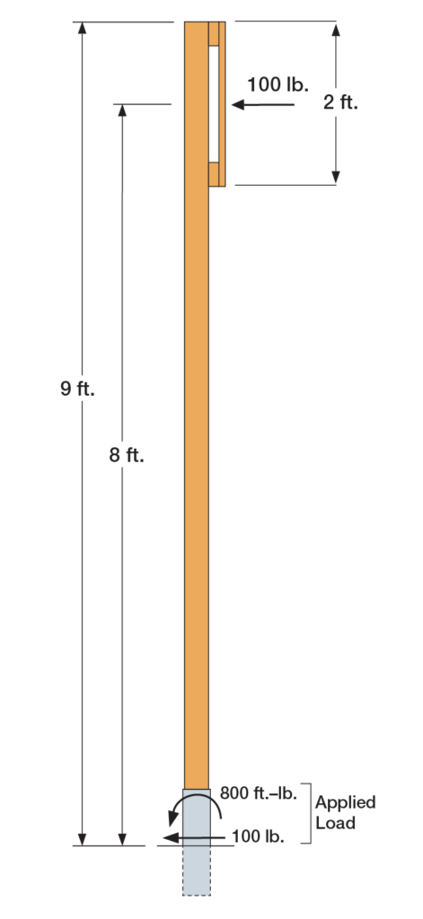
The MPB44Z is used to support a 9ʹ-tall 4×4 post with a 2ʹ x 2ʹ sign mounted at the top. The wind load acting on the surface of the sign is determined to be 100 lb. The MPB44Z is installed into concrete that is assumed to be cracked.
- The design lateral load due to wind at the MPB44Z is 100 lb.
- The design moment due to wind at the MPB44Z is (100 lb.) x (8 ft.) = 800 ft.-lb.
- The Allowable Loads for the MPB44Z are:
- Lateral (F1) = 1,280 lb.
- Moment (M) = 985 ft.-lb.
- Simultaneous Load Check:
- 800/985 + 100/1,280 = 0.89. This is less than 1.0 and is therefore acceptable.
We are very excited about our new MPBZ! We hope that this product will get you excited about your next open-structure design. Let us know your thoughts by providing comments here.


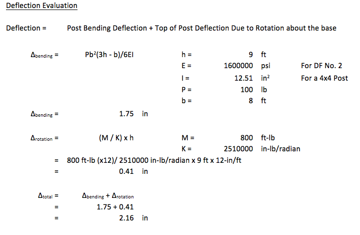

Why do you not have to use a K factor of 2.1x 8′-0″ x 12 = 201.6″ for L ?
Good observation, Joe. It will be dependent on the nature of the frame system containing the post. Here, K was just assumed to be unity for illustration purposes.
It seems that the head of the column is touching the ground, or am I wrong?
Would be fun to visit that lab!
I could imagine that the bottom end of the post extends to the bottom of the sleeve. Am I correct?
Look at figure number 2, the post sits 1 inch above the concrete pour.
Really? Thanx!
Has shrinkage of the wood been considered? It would seem that the even a small amount of shrinkage would have a significant effect on performance and large shrinkages could strip the threads of the SDS screws. This could be a concern for low humidity environments.