Wood shearwalls are typically used as a lateral-force-resisting system to counter the effects of lateral loads. Wood shearwalls need to be designed for shear forces (using sheathing and nailing), overturning (using holdowns), sliding (using anchorage to concrete) and drift, to list some of the main dangers. The Simpson Site-Built Shearwall Designer (SBSD) web app is a quick and easy tool to design a wood shearwall based on demand load, wall geometry and design parameters.
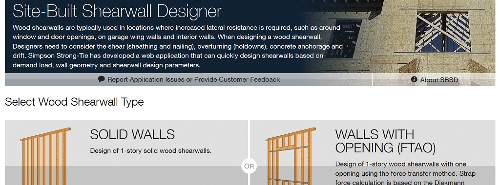
The web application provides two options for generating an engineered shearwall solution: (1) Solid Walls; and (2) Walls with Opening using the force-transfer-around opening (FTAO) method. Both options generate solutions that offer different combinations of sheathing, nailing, holdowns, end studs and number/type of shear anchors. The app can generate a PDF output for each of the possible solutions. Design files can be saved and reused for future projects.
App Overview
Design Input:
Figure 1 shows the input screens for the “Solid Walls” and “Walls with Opening” designs with common wall parameters that are applicable to both design options. The user interface uses quick drop-down menu and input fields for the designer to select the different options and parameters. Unless otherwise noted, all the input loads are to be nominal (un-factored) design loads. The application will apply load combinations to determine the maximum demand forces for the shearwall design.
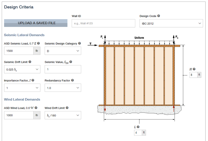


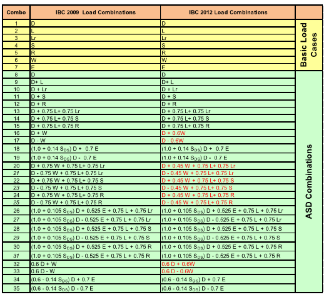
Figure 2 shows the allowable stress design (ASD) load combinations used for calculating the demand loads for the different components of the wood shearwall (i.e., holdown, compression post, sheathing and nailing design, etc.).
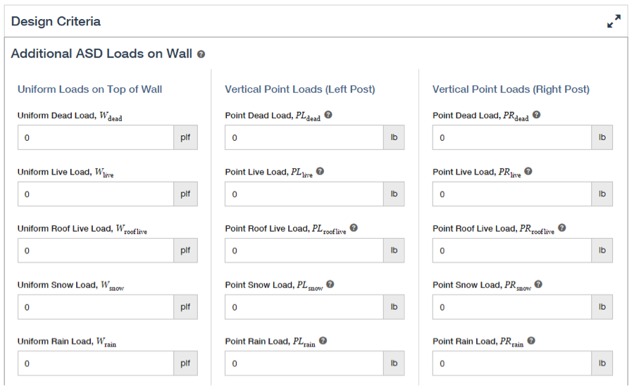
In addition to the lateral loads (wind and seismic) applied at the top of the wall and the wall’s own weight, uniform loads on top of the wall and concentrated point loads at the end posts can also be modeled. (See Figure 3.)
Embedded anchor or embedded strap holdowns can be modeled by the app. (See Figure 4.) For the embedded strap option, additional input parameters are required since they will affect the allowable load of the selected strap holdown.

The Designer has the option to include additional sources of vertical displacement for drift calculation. (See Figure 5.)

Design Calculations:
For hand-calculated design when the demand forces are determined, the holdown size and shear anchorage can be selected from tabulated values. Design for the sheathing/nailing and compression post is relatively straightforward as well; however, the shearwall drift calculation may take a bit more work. This is where the SBSD app comes in handy. Below are two sections on the shearwall drift and strap force calculations and assumptions used in the SBSD application. If you are interested, please contact Simpson Strong-Tie for other design assumptions used in designing the SBSD app.
Shearwall Deflection Calculations:
Equation 1 shows the shearwall deflection equation from the 2008 Edition of Wind & Seismic Special Design Provisions for Wind and Seismic (SDPWS).
The Δa value from the third term of the equation is the total vertical elongation of the wall holdown system from the applied shear in the shearwall. The third term accounts for the additional displacement from holdown displacement. For holdown deflection, the deflection value depends on the post size used with the holdown size. When hand-calculating shearwall drift, Designers may have to perform a couple of iterations to come to the final post and holdown size. The SBSD app accounts for the holdown displacement and the post size used for overturning force calculation.
For shearwall-with-opening deflection calculation, EQ-2 is used in the SBSD app.
The solid wall, ∆solid wall, term is calculated using EQ-1 above. For the window strip and wall pier deflection terms, the height “h” used in EQ-1 is taken as the height of the window opening. ∆a is the deflection from nail slip in the shearwall. For more information regarding shearwall deflection with opening, please refer to Example 1 in Volume 2 of the 2015 IBC SEAOC Structural/Seismic Design Manual.
Strap Force Calculations:
For the Wall with Opening design option, there are several methods (Drag Strut, Cantilever Beam, SEAOC/Tompson, Diekmann) to calculate the force transfer around the opening. In the SBSD app, the Diekmann technique is used to calculate the pier forces in the shearwall and the strap forces around the opening. When calculating the strap forces, the SBSD app assumes they are the same at the top and bottom of the opening. In addition, contribution of the gravity load only affects the overturning forces in the holdown and post design but not the wall pier forces or strap forces.
Design Output:
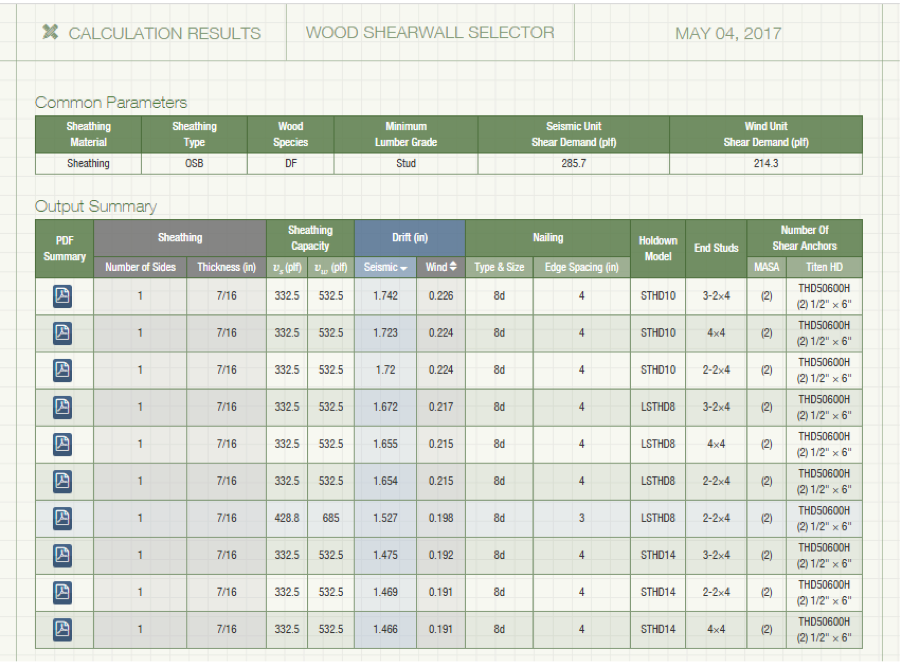
Once all design parameters are entered and calculated, a list of possible solutions (where available) will be shown. (See Figure 6.) Common parameters such as sheathing material and type, wood species, minimum lumber grade, etc., are shown first, followed by other design parameters. The user can filter the solutions by seismic drift or wind drift.
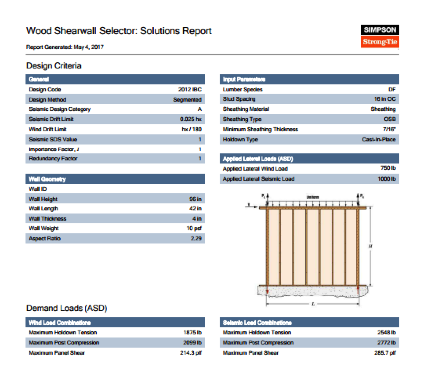
The Designer can select the PDF button next to the desired solution to see a PDF design file on a separate screen. (See Figure 7.) The PDF design file contains the detailed design criteria input by the Designer, calculated demand loads, shearwall material summary, and a design summary for holdown, sheathing, and compression post design. A detail summary for shearwall deflection is also shown, with each term of the shearwall deflection equation (EQ-1) separated. Shear anchorage and design assumption notes follow the design summary section. This PDF file can be saved and printed by the Designer.
I hope you find the SBSD web app helpful for your day-to-day wood shearwall design needs. If you have any questions or comments, please leave them in the comments section below.




Are there any plans to add site-built portal frame shear walls as allowed by code?
Interesting.