

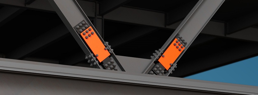
The Yield-Link brace connection (YLBC) from Simpson Strong-Tie is an innovative solution for isolating damage to ensure that braced frames within structural steel buildings remain intact during a seismic or wind event. With predesigned, bolted connections, the YLBC simplifies design work, eliminates the need for field welding, and is easy to incorporate into new builds or retrofits.
With the introduction of the Simpson Strong-Tie Yield-Link® brace connection for steel construction, the engineering and software development teams at Simpson Strong-Tie created multiple software tools to support users in their specification and detailing of the Yield-Link brace connections. The Yield-Link brace connection simplifies structural steel design while providing a connection that keeps steel buildings strong and safe.
We’re hosting a series of webinars to help the structural steel community learn about the Yield-Link brace connection and how to use our software tools to incorporate the connection into their structural steel designs and details.
This webinar series covers the topics below. Each webinar will include a live Q&A session with the speakers.
#1: Simpson Strong-Tie Webinar: Design a Highly Resilient Steel Structure
On May 25, we hosted part one of our four-part webinar series on the latest design solutions for braced frame connections. In this webinar, we discuss our innovative solutions such as the use of predesigned bolted connections that simplify design work and eliminate the need for any field welding, thereby ensuring a highly resilient steel structure, improving safety, and reducing overall project schedules and costs.
If you missed or would like to revisit this webinar, a recording is available for viewing at the above link. As with our previous webinars, we ended with a Q&A session for the attendees. Our Business Development Manager, Tim Ellis, and Engineer, Mary Nunneley, answered as many questions as they could in the time allowed. Now we are back to recap some of the commonly asked questions and their answers, but if you’d like to see the full list, click here.
- Please describe the stiffness of the Simpson brace compared to a BRB with equal force resistance. Are the total inelastic strains equivalent?
- The equivalent stiffnesses of the BRB and YLBC are generally similar for typical brace configurations. That said, the stiffness for each varies by bay configuration and other parameters such that they are not analogous across structures. One advantage of YLBC is that the stiffness can be determined with certainty upon selection of a fuse configuration and brace size (no stiffness modifier is needed).
- Design with YLBC is not dependent on a calculated strain as it is with a traditional BRBF. Adjusted fuse configuration strength (maximum force the fuse can deliver to the system) can be determined from fuse deformations associated with the design story drift (no strain calculation is required). The axial force action in the brace induces internal shears and flexure within the fuse component, rather than axial strain in a BRB core. As a result, there is no direct correlation of inelastic strains between the two products.
- Are these restricted in use to wide flange shapes? Or could they be used with other shapes?The brace is limited to a W14x wide flange member. The beams, columns, and struts could be used with a HSS member. That detailing would be very similar to what you would see on any other system. The proprietary portion of the YLBC is the brace-to-gusset connection.
- In full-scale tests, did both ends yield? If they did, were the peak and residual strain equal in both? Are links required at both ends?
- Yes, both ends yielded. The intent of the loading protocol in AISC 341 Section K3 is that the first two cycles are meant to yield the product.
- The peak and residual strain are fairly similar up until the larger deformation demands, then they begin to vary based on whether the fuses were in compression or tension.
- In seismic design categories A, B, and C, configurations are only required on one end of your brace. In higher seismic design categories, there is an option to use one or two based on the story drift of the structure. We’ve outlined those requirements in our code report ICC-ES ESR-4342.
- Would you recommend using these in buildings that are controlled by wind loading?Yes, this can be designed for an R=3; or if you want a more robust wind design, you can bump it up to an R=8. Even in a low seismic or wind area, using that larger R=8 could really be beneficial for your project in reducing the base shear, which results in more economical drag connections and foundations.
- What is the maximum building height these brace systems can apply?The maximum height that we are qualified for is consistent with the system limitations that are stated in ASCE 7-16 for BRBF. There are multiple variables such as vertical loading, architectural design, and seismic loads that affect the applicability of any lateral system. We see this consistently being able to capture the four- to five-story, mid-height steel structures.
#2: Simpson Strong-Tie Webinar: Enhancing Structural Performance: Exploring the Yield-Link® Brace Connection Design
On June 27, we hosted part two of our four-part webinar series on the latest design solutions for braced frame connections. In this webinar, we take a more in-depth look into the design requirements of the Yield-Link® brace connection. We discuss the various product configurations, the ICC report and how the Yield-Link® brace connection can benefit your structural steel design.
If you missed or would like to revisit this webinar, a recording is available for viewing at the above link. As with our previous webinars, we ended with a Q&A session for the attendees. Our Group Product Manager, Clifton Melcher, and Engineer, Mary Nunneley, answered as many questions as they could in the time allowed. Now we are back to recap some of the commonly asked questions and their answers, but if you’d like to see the full list, click here .
- Do fuse pairs need to be on 2 sides, or can they be on one side?The YLBC fuse plates must be used in pairs and installed symmetrically on each side of the brace web in accordance with ICC-ES ESR-4342.
- Are fuse plates only designed for LRFD or are there product guides for a design using ASD?The available strengths of the YLBC in ESR-4342 are currently only provided in LRFD. There’s no reason you couldn’t design using ASD loads, but we would need to provide those capacities to you. Please reach out to your local Simpson Strong-Tie representative to request the ASD design strengths.
- After the fuse was activated by a seismic event, how is the connection restored? Does one replace the fuse section, and if so, how does one align the new fuse into the place of the old one, as the beams may no longer be exactly aligned after the seismic event?This can vary depending on the situation, and the realignment of the building would need to be determined on a case-by-case basis. This issue is not unique to the YLBC system, and a solution would need to be evaluated for each structure. When compared to other concentric braced frames, the YLBC has the benefit of utilizing relatively small replaceable parts at the end of the brace. We successfully proved in our full-scale test program that the fuse plates protect the brace, columns, beams, and gusset plates as intended and you will simply have to replace the fuses.
- Fuses compress and extend to dissipate energy, so how do they add stiffness to the structure? In the case of torsion control, we need stiffness.The fuse plates have an elastic axial stiffness, as provided in table 1 of ESR-4342, that will be applied to the bay that includes the YLBC. The addition of the brace and YLBC will make the bay stiffer than it would be without these elements. Although the amount of lateral stiffness of the bay is important, the location of the LFRS bays relative to the center of mass and the other LFRS elements will affect your torsional stiffness as well. Care must be given to the layout of each LFRS element to control torsion.
- Can we combine the Yield-Links with BRBs instead of wide flanges so we can have a potentially shallower brace member?A more economical solution would be to use the YLBC with HSS braces. We are currently exploring this for potential revisions to the ESR.
#3: Simpson Strong-Tie Webinar: Yield-Link® Brace Connection Software Demonstration
On July 26th, we hosted part three of our four-part webinar series where we discussed how to incorporate the Yield-Link brace connection using your current software. In this session, we demonstrated our Tekla and ETABS-SAP2000 plugins, as well as the RAM Structural System. We used project examples to show how seamlessly our various software tools and plugins work together to help you quickly and comprehensively model, analyze, design, and detail the Yield-Link brace connection.
If you missed or would like to revisit this webinar, a recording is available for viewing at the above link. As with our previous webinars, we ended with a Q&A session for the attendees. Our Software Project Manager, Vince Yang, answered as many questions as he could in the time allowed. Now we are back to recap some of the commonly asked questions and their answers, but if you’d like to see the full list, click here.
- Are all of these calculations always done by the EOR, or is there a portion of this that is deferred and designed by Simpson like it is for a BRB?All our tools are intended to provide solutions that the engineer can design completely on their own. However, Simpson engineers are available to help you optimize the design. If it’s your first time using the software, we can help walk you through how to use it for your specific project all the way to detailing.
- Similar question to the one asked above. If we are going to use this system, is it intended that we incorporate Simpson’s standard details into the stamped construction documents, or is that more of a shop drawing item?The standard details are intended to be on the stamped drawings that you submit to the city, so you would want to include that on your submittal package to the city plan check department. The Tekla plugin will help the fabricators create the shop drawings, which you can then review. Simpson can help take a look at that, as well.
- Is there a plan to integrate with SDS2?Yes, we are working on a plugin/script for SDS2. It should be available by the end of the year.
- Is the Excel file required for the complete design of frames?Currently, RAM can perform and design the members (beam/column/brace) and the YLBC fuses. It can’t do the connection design. This is where our Excel tool comes in. You can export data from RAM and import it into our Excel tool to finish the connection designs.
- Will this be available in RISA 3D?We initiated a discussion with RISA. But if you would like to see YLBC in RISA 3D, please email RISA and put in a new feature request.
https://training.strongtie.com/courseware/Webinars/VCYLBCD23/WebinarQ&A_0000031809.PDF
#4: Simpson Strong-Tie Webinar: Seismic Resilience and Risk Assessment of the Yield-Link® Brace Connection
On September 14th, we hosted the final webinar of this series where we discussed how to achieve seismic resiliency in steel construction with the Seismic Performance Prediction Program (SP3) by Haselton Baker Risk Group. In this session, we learned about the new Yield-Link brace connection (YLBC) addition into the SP3 software, including the methodology and research behind the SP3 assessment, the structural fragility of the YLBC, structural response prediction engine, and how the YLBC can be used for resilient design for functional recovery in structural steel buildings.
If you missed or would like to revisit this webinar, a recording is available for viewing at the above link. As with our previous webinars, we ended with a Q&A session for the attendees. Our Director of Strengthening, Jeff Ellis, and the Founder and CEO of Haselton Baker Risk Group, Curt Haselton, answered as many questions as they could in the time allowed. Now we are back to recap some of the commonly asked questions and their answers, but if you’d like to see the full list, click .
- As most building interiors are finished, are YLBC locations typically marked for quick identification, checking, and replacement after an event?
This wouldn’t be a requirement for a building owner; however, it would be beneficial to know the location of the braces for repair. FEMA recently developed and published FEMA P-2005, which is a guide for accelerated building re-occupancy programs. This lays out best practices for agreements between the building owner, design professional, engineer, and the local government to allow building owners to get back up and running soon after a seismic event. The following Simpson Strong-Tie SE Blog goes into further detail on this.
2. Is there any limit to the number of stories in an existing building to make it resilient?
The SP3-RiskModel can analyze any building height, although >100 stories will require some technical support from the HB-Risk team (since we put some limits in the user-interface). The tallest resilient design/assessment we have supported to date is ~60 stories, but this is not a limit and buildings taller than this also work. (In fact, we find that it is easier to make most code-compliant tall buildings resilient, as compared with low-rise and mid-rise.)
3. It’s my understanding that Japan has been building seismic resiliency into its buildings for years. How do the US codified efforts compare to what’s been in place overseas?
Japan designs for higher forces and less ductility demand. Although this design methodology can result in a more resilient lateral-force-resisting system, there may be issues with the nonstructural components of the building and therefore longer time to functional recovery. The current effort for US codification of seismic resiliency will address both the structural and nonstructural components of the building in order to improve community resiliency. For a fun side note, the SP3-RiskModel is also enabled in Japan, and Japanese companies and researchers were involved in extending the methods and automation to support Japanese construction.
4. If the residual story drift exists, does the replacement of YLBC include the replacement of the W14 brace? Note that with residual deformation, the new YLBCs should not be able to be directly fit into the deformed frame. The bolt spacing between the brace end and the gusset plate got changed!
No, the W14 brace would not need to be replaced because it is designed to be elastic. The concern of residual drift is present for all lateral systems. However, the information that was presented in this webinar using the SP3 program shows that buildings using the Yield-Link® brace connection have less residual drift than code-specified LFRS. Furthermore, the YLBC in combination with a welded backup frame reduces the likelihood of residual drift being an issue post-earthquake. The fit-up of the YLBC connection after an event would involve an evaluation from the EOR and contractor to determine the means and methods of replumbing the building.
5. Where do we get SP3 software?
The link to SP3 website can be found here.
