


It is hard to believe it has been almost two years since I posted The Anchorage to Concrete Challenge – How Do You Meet It? That post gave a summary of the challenges engineers face when designing anchorage to concrete. Challenges include just doing the calculations (software helps), developing a high enough load, satisfying ductility requirements or designing for overstrength. Over the past several years, Simpson Strong-Tie has worked closely with the Structural Engineers Association of Northern California (SEAONC) to help create more workable concrete anchorage solutions for light-frame construction.

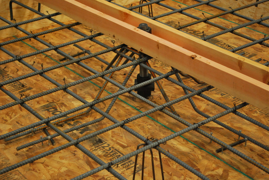
This month’s issue of Structure magazine has an article, Testing Tension-Only Steel Anchor Rods Embedded in Reinforced Concrete Slabs, which provides an update on the ongoing work of SEAONC and Simpson Strong-Tie. The goal of the testing program is to create a useful design methodology that will allow structural engineers to develop the full tensile capacity of high-strength anchor rods in relatively thin (10” to 14”) podium slabs.
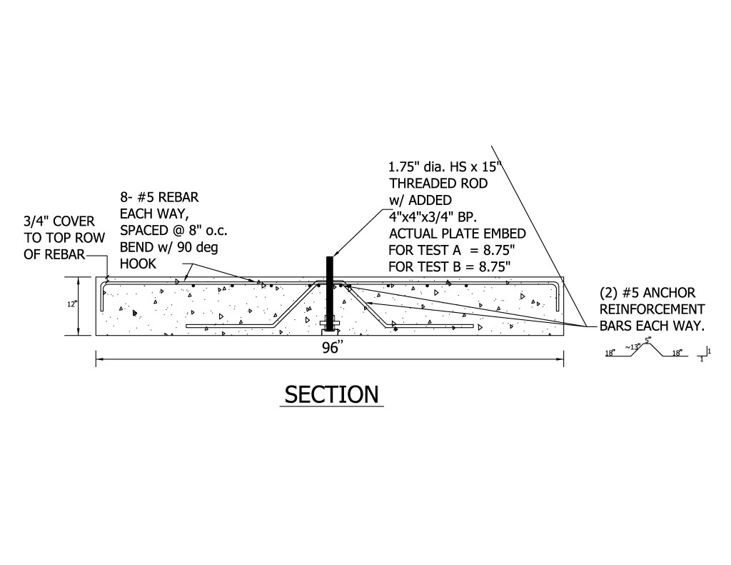
Anchor capacity is limited by steel strength, concrete strength, embedment depth, and edge distances. One way to achieve higher anchor strengths is to design anchor reinforcement per ACI 318-19 Chapter 17.
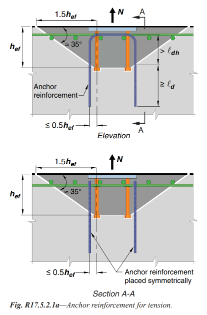
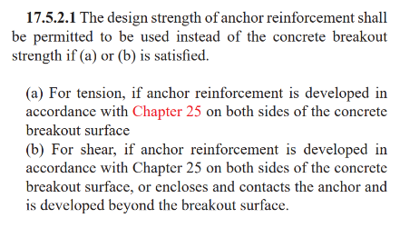
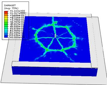
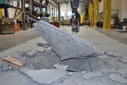
Section 17.5.2.1 requires anchor reinforcing to be developed on both sides of the breakout surface. Since this is not practical in thin podium slabs, alternate details using inclined reinforcing perpendicular to the breakout plane were developed and tested.
This month’s Structure magazine article summarizes the test results for anchors located at the interior of the slab, away from edges. Additional testing is needed for anchor solutions at the edge of slab. The anchor reinforcement concepts are similar, yet additional detailing is required to prevent side-face blowout failure modes. This testing is in progress at the Tyrell Gilb Research Laboratory and will be completed later this year.
Did you read the Structure article? What are your thoughts?