

With the use of engineering software tools, structural engineers can design buildings faster and more efficiently than ever before. In this blog post, Clifton Melcher, P.E., a senior project manager for cold-formed steel connectors, discusses the various enhancements included in version 2.5 of Simpson Strong-Tie® CFS Designer™ software.
Continue Reading
Tag: anchorage
Holdown Anchorage Solutions
A couple years ago, I did a post on selecting holdown anchorage solutions. At the time, we had created a couple engineering letters that tabulated SSTB, SB and PAB anchor solutions for each holdown to simplify specifying anchor bolts. About a year later, a salesperson suggested we tabulate SSTB, SB and PAB anchor solutions for each holdown. You know, to simplify specifying anchor bolts…
This conversation reminded me of the difficulty in keeping track of where design information is. In the C-C-2024 Wood Construction Connectors catalog, we have added this material on pages 46-47. Which should make it easier to find. I thought I should update this blog post to correct the links to this information.
A common question we get from specifiers is “What anchor do I use with each holdown?” Prior to the adoption of ACI 318 Appendix D (now Chapter 17 – Anchoring to Concrete), this was somewhat simple to do. We had a very small table in the holdown section of our catalog that listed which SSTB anchor worked with each holdown.
Continue Reading

Considerations for Designing Anchorage in Proximity to Abandoned Anchor Holes
 This week’s post comes from Dan Harmon, an R&D engineer for Simpson Strong-Tie’s Infrastructure-Commercial-Industrial (ICI) group. Dan specializes in post-installed concrete anchor design and spent a decade managing Simpson’s anchor testing lab, where he developed extensive knowledge of anchor behavior and performance. He has a Bachelor of Science in mechanical engineering from the University of Illinois Urbana-Champaign.
Designers and engineers can spend hundreds of hours on detailed drawings of structures, but there are often conditions and coordination that can change well-planned details and drawings. As we all know, paper and reality don’t always agree. Anchorage locations can move as a result of unforeseen circumstances such as encountering reinforcing bars in an existing concrete slab or interference between different utility trades.
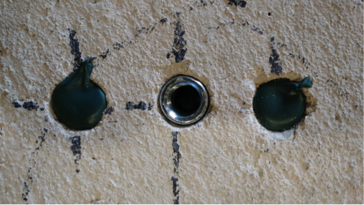
With post-installed anchors, one particular jobsite change may require abandoning a hole that has been drilled, leaving the final anchor location adjacent to the abandoned hole. When a hole for an anchor is drilled but never used, it essentially creates a large void in the concrete. Depending on where this void is located in relation to an installed anchor, there is potential for the capacity of that anchor to be reduced. To give guidance on this situation to specifiers, users and contractors, Simpson Strong-Tie conducted a large series of tests in their ISO 17025–accredited Anchor Systems Test Lab in Addison, Illinois.
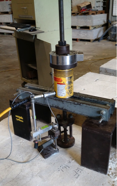
To evaluate the effect of abandoned holes located adjacent to post-installed anchors, we performed tension tests meeting the requirements of ASTM E488-15 (see Figure 1). A variety of anchor types with common diameters were tested:
- Drop-in anchors (1/2″ and 3/4″ diameter)
- Wedge-type anchors (1/2″ and 3/4″ diameter)
- Concrete screws (1/2″ diameter)
- Adhesive anchors with threaded rod (1/2″ diameter)
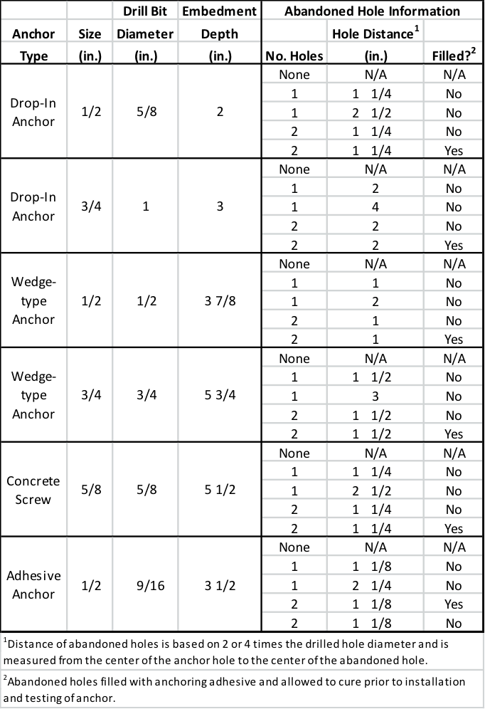
Each anchor type and diameter was tested under five different conditions:
- No abandoned hole near the installed anchor. This is considered the reference condition to which other tests are to be compared.
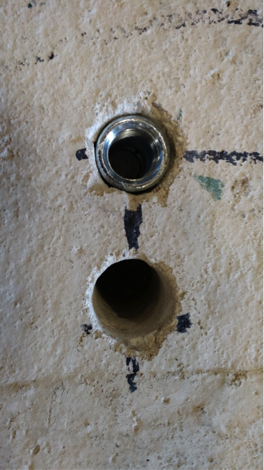
- One abandoned hole at a distance of two times the hole diameter (2d) away from the installed anchor. See Figure 2.
- One abandoned hole at a distance of four times the hole diameter (4d) away from the installed anchor.
- Two abandoned holes, each at a distance of two times the hole diameter (2d) away from the installed anchor. In test conditions with two holes, the holes were located on either side of the installed anchor, approximately 180º from each other. See Figure 3.
- Two abandoned holes, each at a distance of two times the hole diameter (2d) away from the installed anchor, with the holes refilled with a concrete anchoring adhesive that was allowed to cure fully prior to testing. See Figure 4.

This test program is summarized in Table 1. In all cases, the abandoned hole was of the same diameter and depth as the hole prescribed for the installed anchor.
Five tests for each anchor under each condition were tested, and the mean and coefficient of variance of each data set were calculated. These calculated values were used to compare the different conditions.
Across the different anchor types and diameters, the test results showed a number of general rules that held true.
Summary Results
Abandoned holes that are 2” or more away from the anchor have little to no effect on the tension performance of the anchor. Compared to the reference condition with no abandoned hole near the anchor, conditions where the abandoned hole was sufficiently far away were found to be essentially equivalent. This equivalence held true even for anchor types that create expansion forces (drop-in and wedge-type anchors) during their installation.
Two abandoned holes have the same effect on performances as one, regardless of distance from the anchor. This testing showed that adding a second abandoned hole near an installed anchor did not adversely affect tension performance in a significant way. Even within distances of 2 inches, performance did not drop substantially – if at all – in conditions involving two abandoned holes as compared to one.
Filling abandoned holes with an anchoring adhesive prior to installation of the anchor improves performance. In all cases tested, filling abandoned holes with adhesives resulted in increased performance compared to leaving the holes empty. In a majority of cases, performance with filled holes was equivalent to performance in the reference condition regardless of the distance from the anchor.
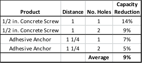
When the abandoned hole is more than two times the drilled hole diameter but less than 2″from the anchor – and left unfilled – the testing showed a loss in performance. Not surprisingly, the degree of that loss was dependent on the type of anchor. Table 2 shows the capacity reduction compared to the reference condition in testing with expansion anchors. Table 3 shows the same results for concrete screws and adhesive anchors. Conservative suggested performance reductions in these conditions would be 20% for expansion anchors and 10% for concrete screws and adhesive anchors.

In an ideal world, the engineer’s designs could be followed at all times at the jobsite. But we don’t live in an ideal world. Good engineering judgment is needed in situations where variation is required, and having data to support those decisions is always helpful. In the case of abandoned holes near post-installed anchors, it’s Simpson Strong-Tie’s hope that this testing provides additional guidance for the designer, inspector, and jobsite worker.

Concrete Anchorage for ASD Designs
One of the first things I learned in school about using load combinations was that you had to pick either Load and Resistance Factor Design (LRFD)/Strength Design (SD) or Allowable Stress Design (ASD) for a building and stick with it, no mixing allowed! This worked for the most part since many material design standards were available in a dual format. So even though I may prefer to use LRFD for steel and ASD for wood, when a steel beam was needed at the bottom of a wood-framed building that was designed using ASD load combinations, the steel beam could easily be designed using the ASD loads that were already calculated for the wood framing above since AISC 360 is a dual- format material standard. And when the wood-framed building had to anchor to concrete, ASD anchor values were available in the IBC for cast-in-place anchors and from manufacturers for post-installed anchors in easy-to-use tables, even though ACI 318 was not a dual-format material standard. (Those were good times!)
Then along came ACI 318-02 and its introduction of Appendix D – Anchoring to Concrete, which requires the use of Strength Design. The 2003 IBC referenced Appendix D for Strength Design anchorage, but it also provided a table of ASD values for some cast-in-place headed anchors that did not resist earthquake loads or effects. This option to use ASD anchors for limited cases remained in the 2006, 2009 and 2012 codes. In the 2015 IBC, all references to the ASD anchor values have been removed, closing the book on the old way of designing anchors.
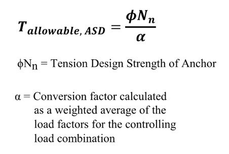 So what do you do now? Well, there is some guidance provided by ICC-ES for manufacturers to convert calculated SD capacities to ASD allowable load values. Since there is no conversion procedure stated in the IBC or referenced standards, designers may want to use this generally accepted method for converting anchor capacities designed using ACI 318. ICC-ES acceptance criteria for post-installed mechanical and adhesive anchors (AC193 and AC308) and cast-in-place steel connectors and proprietary bolts (AC398 and AC399) outline a procedure to convert LRFD capacities to ASD using a weighted average for the governing LRFD/SD load combination. So if the governing load combination for this anchor was 1.2D + 1.6L and the dead load was 1,000 pounds and the live load was 4,000, then the conversion factor would be (1.2)(0.2) + (1.6)(0.8) = 1.52 (keep in mind that the LRFD/SD capacity is divided by the conversion factor in the ICC-ES equation shown here for tension).
Right away, there are a few things that you may be thinking:
- What about load factors that may exist in ASD load combinations?
- It may just be easier to just recalculate my design loads using LRFD/SD combinations!
- The resulting allowable loads will vary based on the load type, or combination thereof.
- If the ACI 318 design strength is limited by the steel anchor, then the conversion will result in an allowable load that is different from the allowable load listed for the steel element in AISC 360.
Let’s take a look at these objections one by one.
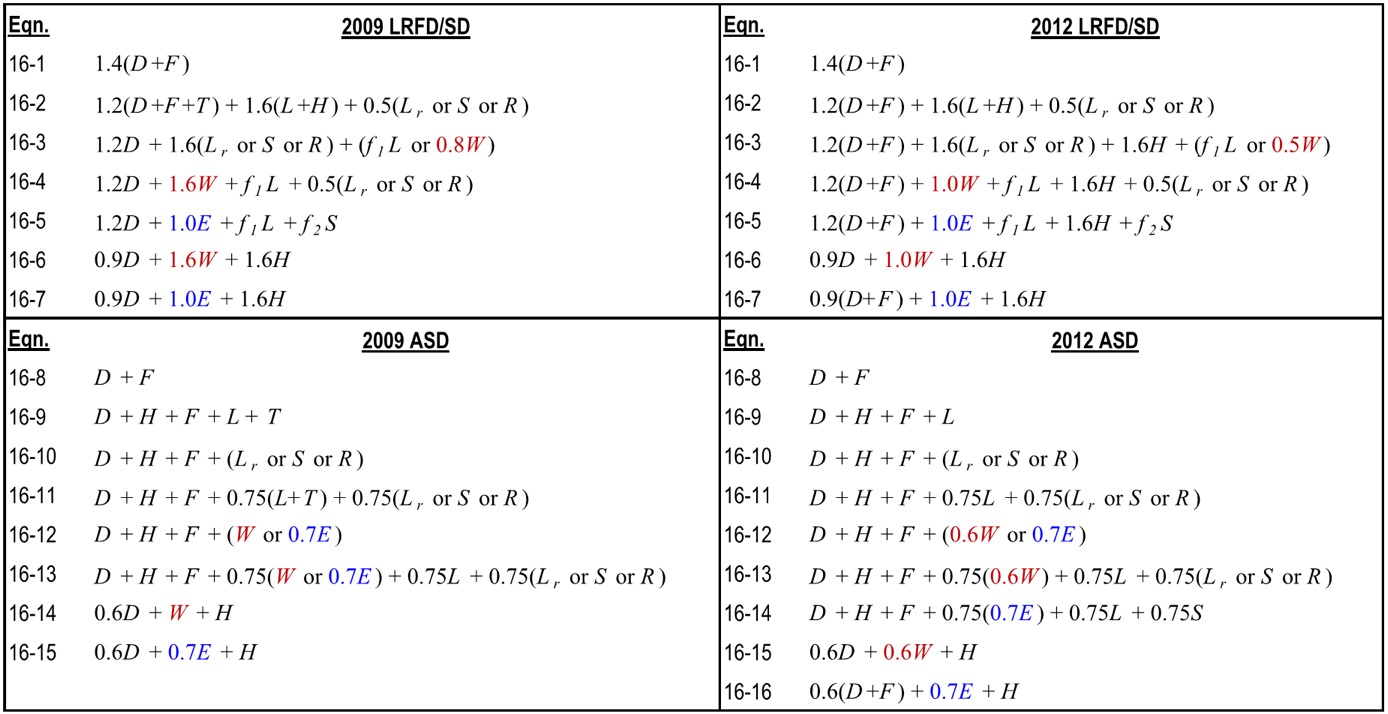
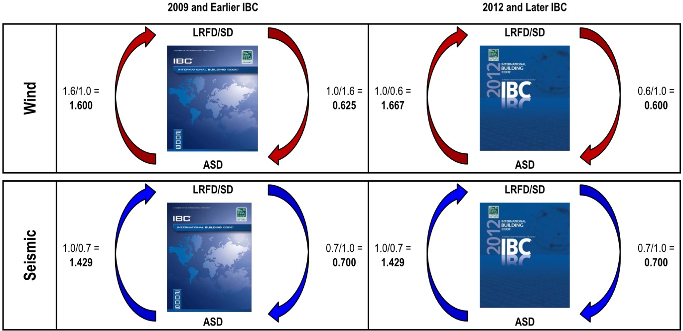
Item 1: Since unfactored earthquake loads are determined at the ultimate level in the IBC, they have an LRFD/SD load factor of 1.0 and an ASD load factor less than 1.0, which is also true for wind loads in the 2012 and 2015 IBC (see graphic below). Using the LRFD/SD load factor of 1.0 obviously does not convert the capacity from LRFD to ASD so you must also account for ASD load factors when calculating the conversion factor. To do so, instead of just using the LRFD load factor, use the ratio of LRFD Factor over ASD Factor. So if the governing load combination for an anchor was 0.9D + 1.0E and the dead load was 1,000 pounds and the seismic load was 4,000, then the conversion factor would be (0.9)(0.2) + (1.0/0.7)(0.8) = 1.32.
Item 2: Even though the weighted average conversion requires you to go back and dissect the demand load into its various load types, often this can be simplified. ICC-ES acceptance criteria permit you to conservatively use the largest load factor. The most common application I run into is working with ASD-level tension loads for wood shearwall overturning that must be evaluated using SD-level capacities for the concrete anchorage. Since these loads almost always consist of wind or seismic loads, using the largest factor is not overly conservative. Depending on the direction in which you are converting the demand loads or resistance capacities, the adjustment factors are as shown in the figure below. Affected Simpson Strong-Tie products now have different allowable load tables for each load type. (For examples, see pp. 33-36 of our Wood Construction Connectors catalog for wind/seismic tables and pp. 28-30 of our Anchoring and Fastening Systems catalog for static/wind/seismic tables.)
Item 3: I am unsure whether there is any sound rationale for having allowable loads for an anchor resisting 10% dead load and 90% live load differ from those of an anchor that resists 20% dead load and 80% live load. Perhaps a reader could share some insight, but I just accept it as an expedience for constructing an ASD conversion method for a material design standard that was developed for SD methodology only.
Item 4: We have differing opinions within our engineering department on how to handle the steel strength component of the various SD failure modes listed in ACI 318. Some believe all SD failure modes in ACI 318 should be converted using the load factor conversion method. I side with others who believe that the ASD capacity of a steel element should be determined using AISC 360. So when converting SD anchor tension values for a headed anchor, I would apply the conversion factor to the concrete breakout and pullout failure modes from ACI 318, but use the ASD steel strength from AISC 360.
Finally, I wanted to point out that the seismic provisions in ACI 318, such as ductility and stretch length, must be considered when designing anchors and are not always apparent when simply converting to ASD. For this reason, I usually suggest converting ASD demand loads to SD levels so you can use our Anchor Designer™ software to check all of the ACI 318 provisions. But for some quick references, we now publish tabulated ASD values for our code-listed mechanical and adhesive anchors in our C-A-2016 catalog — just be sure to read all of the footnotes!

Understanding and Meeting the ACI 318 – 19 Chapter 17 Ductility Requirements – A Design Example
If you’re one of the many engineers still sorting through the anchorage design provisions in ACI 318-19 Chapter 17, this blog will help clarify what’s required to achieve a ductile-performing anchorage. Current building codes (such as the 2024 IBC) reference ACI 318-19 Chapter 17 as the governing provisions for designing a wide variety of anchor types, including expansion, undercut, adhesive, screw, and cast-in-place anchors in concrete. This blog post will focus on Section 17.10.5.3(a) for anchors located in regions of moderate to high seismic risk. We’ll walk through what these requirements mean using a simple design example.
Ductility is a benefit in seismic design. A ductile anchor system is one that exhibits a meaningful degree of deformation before failure occurs. However, ductility is distinct from an equally important dimension called strength. Add strength, and a ductile steel element like the one shown in Figure 1 can now exhibit toughness. During a serious earthquake, a structural system with appreciable toughness (i.e., one that possesses both strength and ductility in sufficient degree) can be expected to absorb a tremendous amount of energy as the material plastically deforms and increases the likelihood that an outright failure won’t occur. Any visible deformations could help determine if repair is necessary.

Let’s start off with a simple example that will cover the essential requirements for achieving ductility and applies to any type of structural anchor used in concrete. We’ll arbitrarily choose a post-installed adhesive anchor. This type of anchor is very common in concrete construction and is used for making structural and nonstructural connections that include anchorage of sill plates and holdowns for shear walls, equipment, racks, architectural/mechanical/electrical components and, very frequently, rebar dowels for making section enlargements. We’ll assume the anchor is limited to resisting earthquake loading in tension only and is in seismic design category C – F. Section 17.10.5.2 requires that if the strength-level earthquake force exceeds 20% of the total factored load, that the anchor be designed in accordance with section 17.10.5.3 and 17.10.5.4. We will focus on achieving the ductility option, (a), of 17.10.5.3.
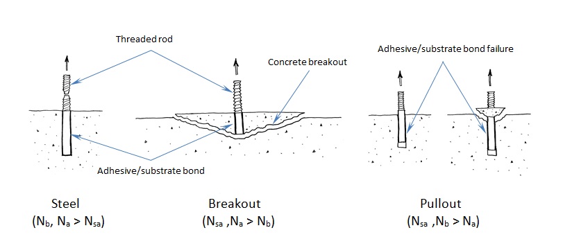
To understand anchor ductility we need to first identify the possible failure modes of an anchor. Figure 2 shows the three types of failure modes we can expect for an adhesive anchor located away from a free edge. These three failure modes generically apply to virtually any type of anchor (expansion, screw, cast-in-place or undercut). Breakout (Nb) and pullout (Na) are not considered ductile failure modes. Breakout failure (Nb) can occur very suddenly and behaves mostly linear elastic and consequently absorbs a relatively small amount of energy. After pullout failure (Na) has been initiated, the load/displacement behavior of the anchor can be unpredictable, and furthermore, no reliable mechanism exists for plastic deformation to take place. So we’re left with steel (Nsa). To achieve ductility, not only does the steel need to be made of a ductile material but the steel must govern out of the three failure modes. Additionally, the anchor system must be designed so that steel failure governs by a comfortable margin. Breakout and pullout can never control while the steel yields and plastically deforms. This is what is meant by meeting the ductility requirements of Chapter 17.
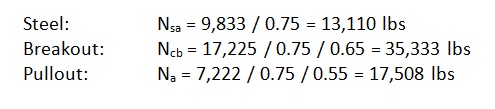
Getting back to our design example, we have a single post-installed 5/8” diameter ASTM F1554 Gr. 36 threaded rod that’s embedded 12” deep, in a dry hole, in a concrete element that has a compressive strength of 2,500 psi. The concrete is 18” thick and we assume that the edge distance is large enough to be irrelevant. For this size anchor, the published characteristic bond strength is 743 psi. Anchor software calculations will produce the following information:

The governing design strength is compared to a demand or load combination that’s defined elsewhere in the code.
Here’s the question: Before proceeding with the remainder of this blog, judging by the design strength values shown above, should we consider this anchorage ductile? Your intuition might tell you that it’s not ductile. Why? Pullout clearly governs (i.e., steel does not). So it might come as a surprise to learn that this adhesive anchor actually is ductile!
To understand why, we need to look at the nominal strength (not the design strength) of the different anchor failure modes. But first let’s examine the equations used to determine the design strength values above:
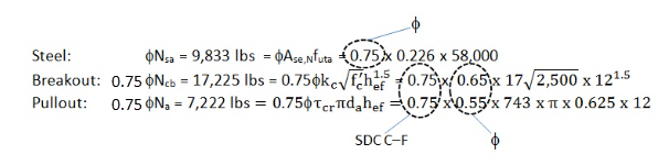
The above values incorporate the notation φ (“phi”) and a mandatory 0.75 reduction factor for nonductile failure modes (Ncb ,Na) for applications located in high seismic areas (seismic design category C–F). The φ factor is defined in section 17.5.3. However, manufacturers will list factors specific to their adhesive based on anchor testing. The mandatory 0.75 reduction comes from section 17.10.5.4 and is meant to account for any reduction associated with concrete damage during earthquake loading. The important thing to remember is that the nominal strength provides a better representation of the relative capacity of the different failure modes. Remove these reduction factors and we get the following:
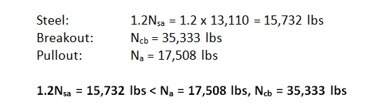
Now steel governs since it has the lowest strength. But we’re not done yet. Section 17.10.5.3.(a).(i) of Chapter 17 requires that the expected steel strength be used in design when checking for ductility. This is done by increasing the specified steel strength by 20%. This is to account for the fact that F1554 Gr. 36 threaded rod, for example, will probably have an ultimate tensile strength greater than the specified 58,000 psi. (Interestingly, the ultimate strength of the ½” threaded rod tested in Figure 1 is roughly 74 ksi, which is about 27% greater than 58,000 psi.) With this in mind, the next step would be to additionally meet section 17.10.5.3.(a).(ii) such that the following is met:

By increasing the steel strength by 20%, the nominal strength of the nonductile failure modes (Ncb ,Na) must be at least that much greater to help ensure that a ductile anchor system can be achieved. The values to compare finally become:
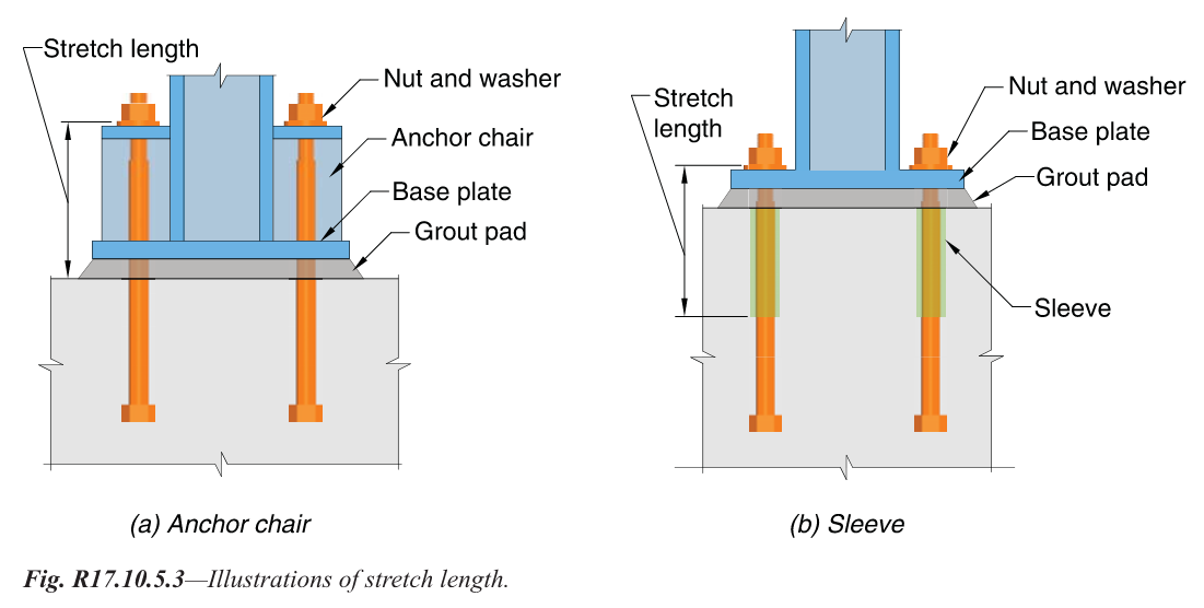
 Now steel governs, but one more thing is required. As shown in Figure 3, Section 17.10.5.3.(a).(iii) of Chapter 17 also requires that the rod be made of ductile steel and have a stretch length of at least eight times the insert diameter (8d). Chapter 17 defines a ductile steel element as exhibiting an elongation of at least 14% and a reduction in area of at least 30%. ASTM F1554 meets this requirement for all three grades of steel (Grade 36, 55 and 105) with the exception of Grade 55 for anchor nominal sizes greater than 2”. Research has shown that a sufficient stretch length helps ensure that an anchor can experience significant yielding and plastic deformation during tensile loading. The threaded rod shown in Figure 1 was tested using a stretch length of 4” (8d). Lastly, section 17.10.5.3.(a).(iv) requires that the anchor be engineered to protect against buckling.
Chapter 17 of ACI 318-19 doesn’t require that an anchor system behave ductilely. Three additional options exist for Designers in section 17.10.5.3. Option (b) allows for the design of an alternate failure mechanism that behaves ductilely. Designing a base plate (or support) that plastically hinges to exhibit ductile performance is one example. Option (c) involves a case where there’s a limit to how much load can be delivered to the anchor. Although option (c) under 17.10.5.3 falls under the tensile loading section of Chapter 17, the best example would apply to anchorage used to secure a wood sill plate or cold-formed steel track. We know from experiments that the wood crushes or the steel yields and locally buckles at a force less than the capacity of the concrete anchorage. Clearly energy is absorbed in the process. The most commonly used option is (d), which amplifies the earthquake load by Ωo. Ωo can be found in ASCE 7 – 16 for both structural and nonstructural components. The value of Ωo is typically taken to be equal to 2.5 (2.0 for storage racks) and is intended to make the anchor system behave linear elastically for the expected design-level earthquake demand.
These same options exist for shear loading cases. However, achieving system ductility through anchor steel is no longer an option for shear loading according to ACI 318 – 19, because the material probably won’t deform appreciably enough to be considered ductile.
While factors such as edge-distance and embedment-depth restrictions make achieving ductility difficult for post-installed anchors, it should come as some consolation that in many cases the Designer can achieve ductile performance for cast-in-place anchors loaded in tension through creative detailing of reinforcing steel (section 17.5.2.1) to eliminate breakout as a possible failure mode. This has been explored in some detail in two previous Simpson Strong-Tie blogs titled “Anchor Reinforcement for Concrete Podium Slabs” and “Steel Strong Wall Footings Just Got a Little Slimmer.”
What are your thoughts? Visit the blog and leave a comment!

Podium Anchorage – Structure Magazine
It is hard to believe it has been almost two years since I posted The Anchorage to Concrete Challenge – How Do You Meet It? That post gave a summary of the challenges engineers face when designing anchorage to concrete. Challenges include just doing the calculations (software helps), developing a high enough load, satisfying ductility requirements or designing for overstrength. Over the past several years, Simpson Strong-Tie has worked closely with the Structural Engineers Association of Northern California (SEAONC) to help create more workable concrete anchorage solutions for light-frame construction.
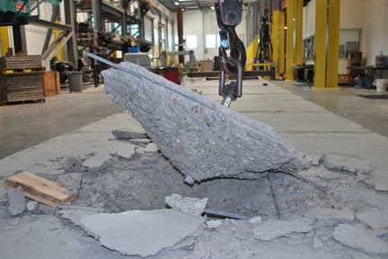

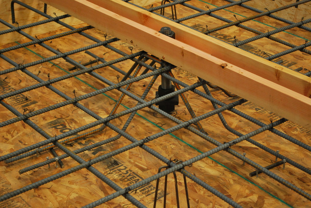
This month’s issue of Structure magazine has an article, Testing Tension-Only Steel Anchor Rods Embedded in Reinforced Concrete Slabs, which provides an update on the ongoing work of SEAONC and Simpson Strong-Tie. The goal of the testing program is to create a useful design methodology that will allow structural engineers to develop the full tensile capacity of high-strength anchor rods in relatively thin (10” to 14”) podium slabs.
Anchor capacity is limited by steel strength, concrete strength, embedment depth, and edge distances. One way to achieve higher anchor strengths is to design anchor reinforcement per ACI 318-19 Chapter 17.
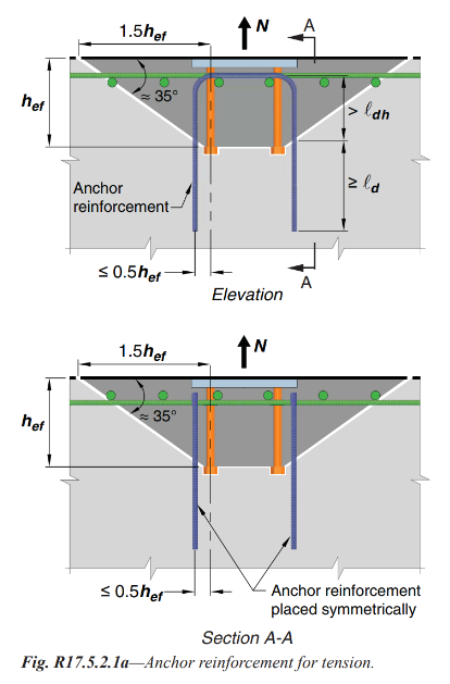
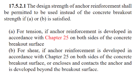
Section 17.5.2.1 requires anchor reinforcing to be developed on both sides of the breakout surface. Since this is not practical in thin podium slabs, alternate details using inclined reinforcing perpendicular to the breakout plane were developed and tested.
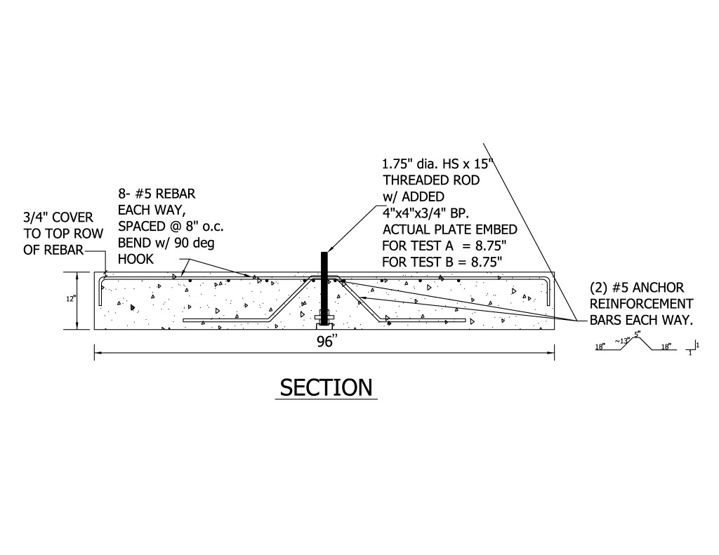
This month’s Structure magazine article summarizes the test results for anchors located at the interior of the slab, away from edges. Additional testing is needed for anchor solutions at the edge of slab. The anchor reinforcement concepts are similar, yet additional detailing is required to prevent side-face blowout failure modes. This testing is in progress at the Tyrell Gilb Research Laboratory and will be completed later this year.
Did you read the Structure article? What are your thoughts?

The Anchorage to Concrete Challenge – How Do You Meet It?
We structural engineers here at Simpson Strong-Tie have a love/hate relationship with anchorage to concrete. Ever since the introduction of the strength design provisions in the 2024 IBC and ACI 318 Chapter 17, anchorage to concrete has been a challenge for designers, building officials and manufacturers. SEAONC’s recent testing and the resulting code changes offer some relief to wood-frame designers for sill-plate anchor design at the edge of concrete, but many challenges remain.

With the increasing demand for high-density housing and urban infill projects, designers are now faced with anchoring multi-story wood-framed shear walls to relatively thin elevated concrete slabs (typically referred to as podium slabs). Overturning tension anchorage forces at the ends of shear walls in these projects can routinely be in the 40 kip range and even get as high as 60 kips or more.