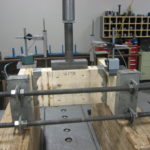
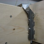
If you have followed some of my earlier blog posts, you know I am passionate about testing. In my post, Testing – Then and Now, I said, “There simply is no substitute for a physical test.” Something I haven’t discussed in much detail, however, are some of the complexities involved in a good test.

For wood connector testing, we follow ASTM D7147-11 Testing and Establishing Allowable Loads of Joist Hangers. The actual testing is relatively straight forward – build at least three setups, test them, measure the deflection and ultimate loads.

It actually was that simple years ago, but modern test standards have more requirements than just breaking the part. First off, the steel used in the connector is important. To prevent overestimating a connector’s performance, ASTM D7147 has limits on the strength and thickness of steel used for testing relative to the specified material.

The test standard acknowledges that actual steel strength will exceed the specified strength and the 3/2.5 term in the reduction factor gives you 20% leeway to exceed the specified minimums and not take reductions in allowable loads. Locating production parts made with the right strength steel requires a little bit of searching and we need to do a base metal thickness test on production parts. Prototype parts are somewhat easier because we can hand pick the steel used for making them.

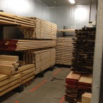
Once we have the parts made with the correct steel in the test lab, we need the right wood. Two properties that affect hanger performance are specific gravity and moisture content of the wood. Moisture content is simply a measure of how wet the lumber is, and the test standards require load reductions if testing is done on wood at less than 11% moisture content. We test the moisture content and specific gravity of every board we receive prior to building test setups. All the good wood is stored in the conditioning room.

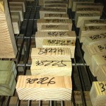
Specific gravity is a measure of how dense the wood is – denser wood usually means better test performance. Similar to steel, the test standard requires reductions if your tested specific gravity exceeds the specified. Unlike steel, there is no 20% fudge factor. Once a test is run, specific gravity samples are taken, numbered, measured, and then put in the oven to dry. With testing complete, we can finish the test report and do the calculations to load rate the product. It is a lot of work to create one allowable load for a table in a catalog or a flier – and I still love testing!
– Paul
What are your thoughts? Visit the blog and leave a comment!


I enjoy your articles. They are short but informative.
Thank you!
What safety factor do you use based on your ultimate load results.
I know for sheet metal screws in light gage metal some manufactures recommend a safety factor of 3 and others recommend 4. I have never understood why the difference.
Maybe on tested more samples or had a smaller standard deviation?
For wood connectors, ICC-ES AC13 and ASTM D7147 require a safety factor of 3 on ultimate and have an 1/8″ deflection limit for serviceability. In addition, the load rating includes a fastener calculation and wood bearing calculation in accordance with NDS standards.
For cold-formed steel connections using tapping screws, AISI S100 has two methods for load rating screw connections. If you are basing the nominal strength on calculations, the safety factor, Ω, is 3 for ASD per Section E4 (ɸ = 0.5 for LRFD).
AISI Section E4 also gives the option to establish design values based on testing, and the resistance factor, ɸ (LRFD) is based on a statistical analysis including the standard deviation of the testing. The calculation of resistance factor, ɸ, is covered in Chapter F equation F1.1-2. The safety factor is calculated as Ω = 1.6/ɸ. So a range of safety factors is possible and it will definitely vary. To avoid confusion, manufacturers should provide ASD and LRFD capacities for designers to use. Nominal capacities should also be provided where appropriate, for example for shearwall holdowns where the code requires the boundary memeber be designed for overstrength loads.
YES.THAT IS REASON FOR FOS DIFFERENCE